
Modelling & Thermal analysis of pulse jet engine using CFD
Rahul Prajapati1 , Prof. Swati D. Chaugaonkar21 M.Tech. Scholar, Department of Mechanical Engineering SGSITS Indore (M.P.) India

2 Professor, Department of Mechanical Engineering SGSITS Indore (M.P.) India ***
Abstract - The pulsejet engines are used as propulsion systems in various types of rockets, missiles, and pilotless aircraft. The objective of current research is to investigate the combustion characteristics of pulsejetenginesusingfiniterate chemistry and an eddy dissipation combustion model using under pseudo-static state conditions. The combustionanalysis is conducted on a pulsejet engine using techniques of “Computational Fluid Dynamics” (CFD). The research findings have shown that proper selection of combustion model is essential for proper evaluation of exit pressure and thrust force generated from pulsejet engine. The pulsejetenginewith the eddy dissipation model is found to generate higher thrust force as compared to the finite rate chemistry model.
Key Words: Fuel Inlet, Pulsejet, Combustion, CFD, Thrust generation.

1. INTRODUCTION
PulsejetEnginesarehollowtubesthatusesoundwavesto drivefluidflowandgeneratethrust.Oneofthemostbasic typesofair-breathingpropulsionthathasbeencreated to dateisthepulsejetengine.Pulsejetenginesareinexpensive to build and maintain since they have few moving components.Thereisnosuchthingasa"misfire"inapulse jet,whichmakesthemlightweight,scalable,affordable,and somewhateffectiveinconvertingfuelintoheatandthrust. Thefundamentalbenefitofpulsejetenginesistheirsimple design, which has no moving parts. Due to these benefits, theyareperfectforutilizationinunmannedaerialvehicles (UAVs). These benefits of the pulse jet engine over an internalcombustionorStirlingengineinclude:
Extremelylow-tech,manufacturedwithfeworno movingcomponents[1].
Due to the fuel's deflagration, it burns highly effectively.
Unlike Stirling engines and internal combustion engines,itcanrunonvirtuallyanykindoffuel.
Itcreatesasubstantialamountofpowerwhileonly weighingaverytinyamount,makingitsuperiorto internalcombustionenginesandStirlingenginesin termsofitspower-to-weightratio.
Itcanfunctionatahighaltitude.Duetoextremely thin air at high altitudes, propeller aircraft are
typicallyrequiredtokeepbelowacertainaltitude. Commercialpassengerairplanestypicallytravelat highaltitudes,forinstance,sinceitismoreefficient (the thin air has relatively little air resistance). Additionally, high-altitude engine performance is requiredforaerospacevehicles(andalsodemands an engine that doesn't breathe air; this second requirement is difficult but might be resolved by changingfuel)[2,3}
2. LITERATURE REVIEW
Ordon et al. [4] Researchers atUniversity of Texas at Arlington constructed a numerical model of a valveless pulsejet that involves combustion in order to assess the effectiveness of a pulsejet with a synchronised injection ignitionsystem.
Kiker et al. [5] Post-World War II, the United States Navy conducted research on pulsejets as part of Project Squid. Engineers at SNECMA in France conducted substantial studiesonpulsejets.LockwoodofHillerAircraft,withthe assistance of French engineers, researchedoperation of pulsejets. This is a significant achievement due to the fact that it isfirst study of its kind that has been extensively recordedandisrigorous.
Gengetal.[6]E.Tharratt'sThenextsignificantadvancement inanalyticalassessmentofpulsejetswasheuristicmethod bylinearizationofahighlynonlinearissue.AttheUniversity of Calgary, Kentfield and his colleagues created the first
computer simulations of cyclic processes of valveless pulsejets.
Sayresetal.[7]Since2004,NorthCarolinaStateUniversity, hasconductedasignificantamountofresearchonpulsejets. This study has includedanalytical, experimental,and numerical studies. These studies have proved that it is possible to operate pulsejets that are as little as 8 centimetersinlength.
Titovaetal.[8]Considerthattheprincipleunderlyingtheir technique is, to begin with relatively simple chemical systemsand then progressivelyadvance tomorecomplex ones.ThisisanalogoustotheworkdonebyWarnatzinthat both make an effort to limitthe number of species and reactions which are required to model combustion. Numerous reactions known to alterignition time are highlightedinthemechanism'srevisions.Theseincludethe additionormodificationofnumerousprocessesthatcreate tocombatOHradicalsfromfuelsandintermediatesspecies andneedforadditionalreactionsteps,particularexamples such as methanol autoignition at high temperatures. In reality,sinceitsinitialreleasein2001,theupdatenoteshave detailed continuous incremental advances in matching ignitiondataquicklyithasbeenprovided.
3. OBJECTIVE
Thepurposeofthisstudyistoapplyfiniteratechemistry& eddy dissipation combustion models to the problem of analyzing the combustion characteristics of a pulsejet engine. The combustion analysis is conducted on pulsejet engineusingtechniquesofComputationalFluidDynamics.
• CAD modeling of new designs with multiple fuel inlets

• CFDanalysisusingANSYS-CFXsoftwareusingnew designwithmultiplefuelinlets
• Determining thrust generated, pressure plot and velocity plot for new design with multiple fuel inlets.
4. METHODOLOGY
TheCFDanalysisisbasedonNavier’sstokesequationwhich involvestheconservationofmomentum,mass,andenergy. Figure2illustrateshowthedesignofthepulsejetenginewas created utilizing design software. The developed model is converted in a compatible file format, i.e., iges. This file format .iges makes this file compatible to be opened in ANSYSsimulationpackage.
Pulsejet engines are depicted in figure 3 above, which depictstheimporteddesign.Pulsejetdesignischeckedfor geometricerrors,imperfectionsetc.Themodelofpulsejet engine is discretized with fine relevance and adaptive meshingtype.Themeshingisdonewithtetrahedralelement typeandfine
After meshing, the loads and boundary conditions are appliedonpulsejetengine,whichinvolvesairinletcondition, fuelinletconditionandairoutletconditions.


The air inlet boundary condition is defined as shown in figure8.Theinletairisdefinedwithdifferentmassfractions of CO2, H2O, Jet A fuel and O2. These conditions of mass fractionsareshowninfigure7.
Thecombustionmodelisdefinedfortheanalysisasshown in figure 6 and is set to eddy dissipation and finite rate chemistryforsubsequentanalysis.


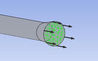
The fuel inlet boundary conditions are defined for the pulsejetdomain,asshowninfigure9.Thefuelinletinvolves definitionofnormalspeed,andmassfractionofJetAfuelis setto1.
The air outlet boundary conditions are defined for the pulsejet engine, as shown in figure 10 above. The outlet boundary condition is defined with 0 relative pressure difference.


5. RESULTS AND DISCUSSION
Thepressuredistributionplotisgeneratedforthepulsejet engine, as shown in figure 11. The plot shows higher
pressure values at the air inlet valves and in the region betweenfuelinletandairinlet.Inapulsejetengine,pressure rises towards the combustion zone and falls further away fromit.
13. The plot shows higher pressure values at the air inlet valvesandintheregionbetweentheairinlet&fuelinlet.In apulsejetengine,thepressureishighestatthecombustion zoneanddecreasesastheenginegetslonger.
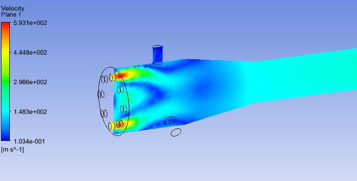
Thevelocitydistributionplotisgeneratedfor thepulsejet engineacrosstheplane,asshowninfigure12.Thevelocity distributionplotshowsahighermagnitudeofdeformation near the air inlet and reduces along the combustion zone. The velocity is uniform along the exit of the nozzle. The maximumvelocitymagnitudeobtainedis590.5m/s.
Thevelocitydistributionplotisgeneratedfor thepulsejet engineacrosstheplane,asshowninfigure14.Thevelocity distributionplotshowsahighermagnitudeofdeformation near the air inlet and reduces along the combustion zone. Thevelocity isuniformalongthe exit ofthe nozzle with a maximummagnitudeof593.1m/s.
6. CONCLUSION
TheCFDsimulationenabledtoinvestigationthecombustion characteristicsofpulsejetengineswithdifferentcombustion models. The research findings have shown that proper selection of combustion model is essential for proper evaluationofexitpressureandthrustforcegeneratedfrom pulsejet engine. The pulsejet engine with the eddy dissipationmodelisfoundtogeneratehigherthrustforceas comparedtothefiniteratechemistrymodel.


• For all the design configurations of the pulsejet engine the combustion zone is observed to have maximum pressure and static enthalpy which reducesalongtheexitofthepulsejetengine.
• Among the several fuel inlets designs for pulsejet engines,the design with three fuel inlets demonstratedthehighestpressuresandthrust
REFERENCES
[1]http://web.archive.org/web/20171120231420/http://g ofurther.utsi.edu:80/Projects/PulseDE.htm
[2]http://news.google.com/patents/about?id=vOZsAAAAEB AJ
[3]http://www.google.com/patents?vid=USPAT6216446
Thepressuredistributionplotisgeneratedforthepulsejet enginewithafiniteratechemistrymodel,asshowninfigure
[4] R.L. Ordon, Experimental investigations into the operationalparametersofa50cmclasspulsejetengine,M.S. Thesis, Department of Mechanical and Aerospace Engineering,NCStateUniversity,Raleigh,NC,27695,2006.

[5]A.P.Kiker,Experimentalinvestigationsonminipulsejet engines, M.S. Thesis, Department of Mechanical and AerospaceEngineering.,NCStateUniversity,Rayleigh,NC, 27695,2005.
[6]T.Geng,Numericalsimulationsofpulsejetengines,Ph.D. Dissertation, Department of Mechanical and Aerospace Engineering,NCStateUniversity,Raleigh,NC,27695,2007.
[7]J.S.Sayres,Jr.,Computationalfluiddynamicsforpulsejets andpulsejetrelatedtechnologies,M.S.Thesis,Departmentof MechanicalandAerospaceEngineering,NCStateUniversity, Raleigh,NC,27695,2007.
[8]N.S.Titova,P.S.Kuleshov,A.M.Starik,Kineticmechanism ofpropaneignitionandcombustioninair,Combust.Explos. Shock Waves 47 (No. 3) (2011) 249e264, https:// doi.org/10.1134/S0010508211030014.
[9] G.S.L. Andreis, R.S. Gomes, A.L. De Bertoli, A reduced kineticmechanismforpropaneflames,EngenhariaTermica (Therm.Eng.)11(No.1e2)(2012)37e43.
[10] W.K. Metcalfe, S.M. Burke, S.S. Ahmed, H.J. Curran, A hierarchicalandcomparativekineticmodelingstudyofC1C2hydrocarbonandoxygenatedfuels,Int.J.Chem.Kinet.45 (No. 10) (2013) 638e675, https://doi.org/10.1002/kin.20802.
[11]P.Gokulakrishnan,C.C.Fuller,M.S.Klassen,R.G.Joklik, Y.N. Kochar, S.N. Vaden, T.C. Lieuwen, J.M. Seitzman, Experiments and modeling of propane combustion with vitiation, Combust. Flame 161 (No. 8) (2014) 2038e2053, https://doi.org/10.1016/j.combustflame.2014.01.024
[12]N.Zettervall,K.Nordin-Bates,E.J.K.Nilsson,C.Fureby, Large eddy simulationof a premixed bluff bodystabilized flame using global and skeletal reaction mechanisms, Combust. Flame 179 (2017) 1e22, https://doi.org/10.1016/j.combustflame.2016.12.007.