International Research Journal of Engineering and Technology (IRJET)
e-ISSN: 2395-0056
Volume: 12 Issue: 11 | Nov 2025
p-ISSN: 2395-0072
www.irjet.net
FAULT MONITORING IN SYSTEM USING SIMULINK Deepak Nishad1, Sarita Sahu2, Shruti Mahant 3, Yuvraj suryawanshi4 , Mohini Moitra⁵ 1234
UG Student, Department of Electrical & Electronics Engineering, CEC Bilaspur, Chhattisgarh, India Assistant Professor, Department of Electrical & Electronics Engineering, CEC Bilaspur, Chhattisgarh, India ---------------------------------------------------------------------***--------------------------------------------------------------------faults cause unbalanced system conditions and include one Abstract - The goal of this study is to create a simulation 5
or two phases. Single-line-to-ground, line-to-line, doubleline-to-ground, and three-phase faults are the fault types that are most frequently researched. Asymmetrical faults are more common and complex, necessitating in-depth analytical and simulation-based research, whereas symmetrical faults are less common but usually more severe. Power systems failure analysis and simulation have made extensive use of computational tools such as MATLAB/Simulink in recent years. Because these technologies allow for accurate modeling of transmission lines, generators, transformers, and loads, engineers may analyze system performance under various fault situations. Through their insights into fault current magnitudes, voltage profiles, and system stability during disturbances, the simulated results help build efficient protection strategies. All things considered, fault analysis is an essential part of power system engineering that increases operational dependability, promotes the design of protective mechanisms, and ensures the safety of personnel and equipment. In order to keep electrical networks functional and intact under real-world operating situations, it is essential to have a thorough understanding of failure behavior and how it impacts the system.
model using MATLAB that can be used to examine different kinds of three-phase faults in electrical transmission line systems. Single line-to-ground, double line-to-ground, and line-to-line faults—all of which are frequent in longdistance power transmission networks—as well as symmetrical (triple line-to-ground) faults are included in the study. The changes in system characteristics, such voltage and current, under various fault scenarios are investigated through simulation. The results of this study advance our knowledge of fault behavior and offer a useful tool for MATLAB-based fault analysis and system protection studies.
Key Words: Line to line fault, Line to ground fault, Double line to ground fault, symmetrical and asymmetrical faults, MATLAB software
1. INTRODUCTION The stability and dependability of the electrical energy supply are crucial in contemporary power systems. However, a variety of disruptions and unusual operating situations are constantly present in power systems, which might result in malfunctions. When the current and voltage in a circuit diverge from their typical levels because of insulation failure, short circuiting, or an unforeseen connection of live conductors to the ground or one another, this is known as a fault. If not dealt with quickly and efficiently, such incidents can seriously harm electrical equipment, disrupt the power supply, and even jeopardize the stability and safety of the system.
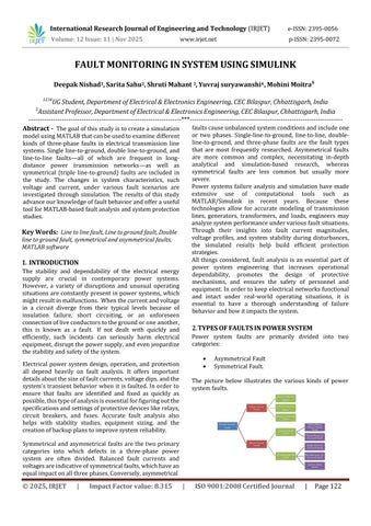
2. TYPES OF FAULTS IN POWER SYSTEM Power system faults are primarily divided into two categories:
Electrical power system design, operation, and protection all depend heavily on fault analysis. It offers important details about the size of fault currents, voltage dips, and the system's transient behavior when it is faulted. In order to ensure that faults are identified and fixed as quickly as possible, this type of analysis is essential for figuring out the specifications and settings of protective devices like relays, circuit breakers, and fuses. Accurate fault analysis also helps with stability studies, equipment sizing, and the creation of backup plans to improve system reliability.
Asymmetrical Fault Symmetrical Fault.
The picture below illustrates the various kinds of power system faults.
Symmetrical and asymmetrical faults are the two primary categories into which defects in a three-phase power system are often divided. Balanced fault currents and voltages are indicative of symmetrical faults, which have an equal impact on all three phases. Conversely, asymmetrical
© 2025, IRJET
|
Impact Factor value: 8.315
|
ISO 9001:2008 Certified Journal
|
Page 122