
International Research Journal of Engineering and Technology (IRJET) e-ISSN: 2395-0056
Volume: 12 Issue: 04 | Apr 2025 www.irjet.net p-ISSN: 2395-0072
![]()

International Research Journal of Engineering and Technology (IRJET) e-ISSN: 2395-0056
Volume: 12 Issue: 04 | Apr 2025 www.irjet.net p-ISSN: 2395-0072
Shreya Vijith1 , H P Shinde2
1Student, Dept. of Mechanical Engineering, COEP Technological University, Pune, MH, India
2Proffessor, Dept. of Mechanical Engineering, COEP Technological University, Pune, MH, India
Abstract - Designing injection-molded plastic components necessitates the effective integration of secondary geometric features such as ribs and bosses, which serve to improve mechanical strength, reduce material usage, and facilitate assembly. However, these features often introduce complexitiesin moldability,manufacturability,andstructural performance. As a result, their accurate detection and validation within Computer-Aided Design (CAD) systems is essential during the early stages of product development.
This review examines existing literature on the automated recognition and evaluation of ribs and bosses in CAD environments. Emphasis is placed on rule-based algorithms, geometric reasoning, and topology-informed validation techniques. Methods are analyzed based on recognition accuracy, adaptability to irregular geometries, compliance with design for manufacturability (DFM) standards, and effectiveness in handling hybrid or intersecting features.
In addition, the mathematical and logical underpinnings suchasedgeprofiling,faceadjacencyanalysis,anddraft-angle filtering arediscussed,withspecificfocusontheirlimitations when applied to complex geometries. The review addresses often-overlookededgecases,includingfeaturesonnon-planar surfaces, interconnected bosses and ribs, and variable crosssection profiles. Rather than providing a descriptive survey alone, the study critically evaluates the practical utility of these approaches, weighing trade-offs among computational complexity,scalability,andCADintegration.Itconcludeswith a set of consolidated best practices and identifies future research directions aimed at developing more adaptive and context-aware validation systems for molded plastic part design
Key Words: Injection Molding, Plastic Component Design, Feature Recognition, Ribs and Bosses, Design for Manufacturability,CADAutomation,GeometricValidation
In the plastics processing industry, injection molding technology is a common technique used to produce complexly geometrized products in large quantities. This method is used in many different industries, such as the production of toys for kids, medical devices, automobile
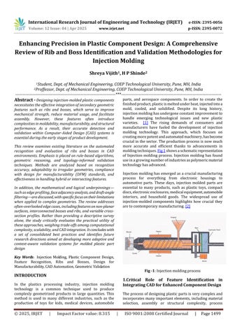
parts, and aerospace components. In order to create the finishedproduct,plasticismeltedunderheat,injectedintoa mold, cooled, and solidified. Despite its long history, injectionmoldinghasundergoneconstantimprovementto handle emerging technological issues and new plastic varieties. [1] The rising demands of consumers and manufacturers have fueled the development of injection molding technology. This approach, which focuses on creatingmorepotentandautomatedmachinery,hasbecome crucialinthesector.Theproductionprocessisnowmuch more accurate and efficient thanks to advancements in moldingtechniques.Fig1showsaschematicrepresentation of Injection molding process. Injection molding has found useinagrowingnumberofindustriesaspolymericmaterial technologyhasadvanced.
Injectionmoldinghasemergedasa crucialmanufacturing process for everything from electronic housings to automotive parts. These days, injection molded parts are essential to many products, such as plastic toys, compact discs,electronicenclosures,medicalequipment,automobile interiors, and household goods. The widespread use of injection-molded components highlights how crucial they aretocontemporarymanufacturing.[2]

1.Critical Role of Feature Identification in Integrating CAD for Enhanced Component Design
Theprocessofdesigningplastic partsisverycomplexand incorporates manyimportant elements, including material selection, assembly or structural complexity, process

International Research Journal of Engineering and Technology (IRJET) e-ISSN: 2395-0056
Volume: 12 Issue: 04 | Apr 2025 www.irjet.net p-ISSN: 2395-0072
constraints, and functional operational life, the mold's longevity,andmanufacturingcosts,successfuldesignsfollow requirements.Inordertoincreasethepart'sessentialdesign elements like wall thickness, draft angles, textures, and featureslikeribsandbosses,aswellasholesordepressions.
Asingleplasticpartdesignwithseveralfeaturesallowsthe parttosatisfyavarietyoffunctionalneedswhilestillmeeting manufacturinglimitations.Forexample,bossesofferstrong, localized points for fastening without sacrificing the part's integrity,whileribsimprovestructuralintegrityandstiffness withoutappreciablyincreasingthemassofthematerialor changing the geometry of the part. To optimize the manufacturingprocessandtheperformanceofthepart,these features must be carefully crafted to work in unison, guaranteeing that each performs its assigned functionand that they complement one another. Manipulation of wall thickness and appropriate drafting ensures that parts are strong yet economical to produce, mitigable for stresses during both the molding process and actual use. Table 1 showsalistoffeaturecategories.Tocreatecomponentsthat arenotonlyfunctionallyandeconomicallyfeasiblebutalso scalable and sustainable to manufacture, good plastic part designnecessitatesadeepcomprehensionandintegrationof these various components, making sure that they work in concert. This comprehensive approach during the design stage is essential for avoiding expensive redesigns and production hold-ups, guaranteeing that the final product satisfiestechnicalspecificationsandmarketexpectations.[3]
Table -1: Apartiallistoffeaturecategories(ordered alphabetically)withuseinformationandexample
1 Assembly feature Used to represent assemblyknowledge Shaftforassembly
2 CAEfeature Used to represent engineering analysis knowledge Stress analysis feature, fluid flow analysisfeature
3 Component feature Used to represent components Wall,column,screw
4 Form feature Used to represent elements characterized via shapeproperties Hole, pocket, chamfer
5 Functional feature Used to represent functionalknowledge Holeforassembly
6 Geometric feature Used to represent a geometricelement Surface, edge, vertex
7 Machining feature Usedtorepresentthe effects of machining processes Amountofmaterial swept during a drillingprocess
8 Material feature Used to represent materialproperties Ceramicfeature
Ribs arethin,wall-likefeatures typically designedinto the geometryofaparttoaddinternal supporttowallsorother featureslike bosses.Similarly, gussetsaresupportfeatures thatreinforceareassuchaswallsorbossestothefloor.Just asbridgebeamsand columnsaresupportedattheirvertex with gussets to add critical strength to the structure, the sameconceptappliestoplasticinjectionmolding.Fig2shows aschematicrepresentationofRibsinaCADModel

Fig -2:RibsinPlasticMoldedParts
They serve several essential purposes in injection molded parts:
1. Strength and Rigidity: Ribs increase the stiffness and strengthofplasticpartswithout significantlyaddingto theirweight.Byprovidingadditionalsupport,theyhelp in distributingstressmoreevenlythroughoutthepart, whichcanbeparticularlybeneficialinlarge,flatsections pronetowarpingorbending.
2. MaterialReduction:Byenhancingstructuralintegrity,ribs allowfora reductioninwallthickness,therebysaving material costs and reducing the cycle time during the moldingprocess.textfile.Youarenowreadytostyleyour paper.
3. Dimensional Stability: Ribs help maintain dimensional stability and reduce deformation in critical areas, ensuringthatthepartsmeetprecisetolerancesandfit togetherasintendedinassemblies
4. Aesthetic Improvement:Strategicallyplacedribscanalso helpmanagetheappearanceofsinkmarksonthevisible surfaces of parts, which are depressions caused by unevencoolingandshrinkage

International Research Journal of Engineering and Technology (IRJET) e-ISSN: 2395-0056
Volume: 12 Issue: 04 | Apr 2025 www.irjet.net p-ISSN: 2395-0072
Abossfeaturefindsuseinmanypartdesignsasapointof attachment and assembly. The most common variety consists of cylindrical projections with holes designed to receivescrews,threadedinserts,orothertypesoffastening hardware. Under service conditions, bosses are often subjectedtoloadingsnotencounteredinothersectionsofa component.Provideagenerousradiusatthebaseoftheboss forstrengthandampledraftforeasypartremovalfromthe mold.Fig3showsaschematicrepresentationofBossesin thesameCADModel

They are typically integrated into plastic parts for the followingreasons:
1. Fastening and Assembly:Bossesprovideanchorpoints for screws, threaded inserts, or other fasteners, facilitatingtheassemblyofmultiplecomponents.Thisis crucialinapplicationswherepartsneedtobesecurely attachedtoeachotherortoothermaterials.
2. Alignment:Theyhelpintheprecisealignmentofparts duringassembly,ensuringthatcomponentsfittogether correctly.Thisisparticularlyimportantinproductsthat requirehighprecisionandconsistency.
3. Housing for Inserts:Bossescanhousemetalinsertsthat providethreadedconnectionsinplasticparts,enhancing thedurabilityandstrengthofthefasteningpoints.
Whendesigningribsandbosses,itisessentialtofollowbest practices to avoid common issues such as sink marks, warping,andresidualstresses.Keyconsiderationsinclude maintaining appropriate rib thickness (typically less than 60% of the wall thickness), adding fillets at the base to reduce stress concentration, and ensuring uniform wall thicknesstopromoteevencooling.
Advancedrecognitiontechniquesplayacrucialroleinthe increasingly complex field of product design and manufacturing, especially for crucial component features like bosses and ribs in CAD models. These feature recognition methods successfully combine the dynamic potential of contemporary CAD technologies with the theoretical underpinnings of design to produce a strong frameworkforenhancingthefunctionalityandappearance ofengineeredproducts.
Bosses and ribs are essential structural and assembly components in a wide range of industries, including electronicsandautomotive,whichemphasizestheneedfor accurateandflexibledesigntechniquesinCADmodels.The mainwaythatribsimprovestructuralintegrityisbygiving plasticcomponentssupportandstiffness.Conversely,bosses play a crucial role in enabling accurate assembly points, particularly for screws and fasteners, and thereby guaranteeing the robustness and durability of the product.[4]
Advanced algorithms that automatically identify and recommend changes to these crucial features have been developedbecauseofthedevelopmentofCADtechnologies. Forexample,bymodifyingthesizeandplacementofribsin response to real-time simulation results, AI-driven tools integratedintoCADsystemscannowanticipateandmodify possible stress points in a design. Similar to bosses, CAD systemswithintelligentdesignalgorithmscanoptimizethe size and layout of bosses according to the applicationspecificconnectivityneedsandmechanicalloads.Fig4and Fig5showClassificationofafewcommontypesofRibsand Bosses.
Using feature-based recognition systems, which can recognizefeaturesstraightfromCADmodelsregardlessof their geometric complexity, is one of the state-of-the-art methods. These systems decipher the underlying geometricalstructuresthatareclassifiedasbossesorribs, suchasextrusions,depressions,andapertures.Thedesignto-manufactureprocessisstreamlinedthanksinlargepart to this automatic recognition, which lowers the time and expense involved in manual repetitions. For instance, sophisticated modules in software such as AutoCAD, SolidWorks, and ProE automate injection mold design details,takingintoconsiderationthepotential mechanical and thermal stresses these components may experience duringproductuse.[5]
Moreover, the introduction of cloud-based CAD platforms hasfacilitatedreal-timecollaborationamongglobalteams, enabling the continuous integration of iterative design

International Research Journal of Engineering and Technology (IRJET) e-ISSN: 2395-0056
Volume: 12 Issue: 04 | Apr 2025 www.irjet.net p-ISSN: 2395-0072
improvements.Theseplatformsallowforseamlessupdates tothefeaturerecognitionalgorithms,ensuringtheyremain attunedtothelatestindustrystandardsandpractices.This not only accelerates the design process but also ensures compliance with international manufacturing norms and safetyregulations.


Thedifficultystillliesinstrikingabalancebetweencreative humaninputandautomateddesignprocesses.Thesubtleties of aesthetic appeal and custom design changes frequently call for expert designer intervention, even though CAD systemsofferpowerfultoolsfordesignoptimization.More user-friendlyCADinterfacesthatenabledesignerstoeasily modify automated recommendations and inject creativity withoutsacrificingtechnicalaccuracyisthefuture.


Thedevelopmentandmodificationofribsandtubesinthinwalled plastic injection parts significantly impact their manufacturability. The approach used for addressing the challenges posed by complex geometric features in such components involves integrating Design for Manufacturability (DFM) analysis with Computer-Aided Design (CAD) modifications. Key to this integration is an effective systemforrecognizing,analyzing,andmodifying specificfeatureslikeribsandtubes.[6]
One of the mathematical models used to analyze these features involves calculating the dimensions of ribs and

International Research Journal of Engineering and Technology (IRJET) e-ISSN: 2395-0056
Volume: 12 Issue: 04 | Apr 2025 www.irjet.net p-ISSN: 2395-0072
tubes to assess their conformity to design guidelines. For ribs,severalkeyparametersareconsidered:
1. Rib Thickness (Tᵣ):Thisiscrucialforensuringtherib's functional and structural integrity. The formula for evaluatingribthicknessmightincludeconsiderationsof thepart'soverallthickness(t)andpositionsrelativeto otherfeatures.
2. Rib Height (Hᵣ):Ribheightisdeterminedbyprojecting thehighestpointontherib'sshellfacetoitsbaseface, aligningwiththemoldopeningdirection,Vᵤ.Thisheight affects how material flows during molding and thus impactsthequalityofthemoldedpart.
Hr=distance(Ph,Pl)wherePl=projectionofPhonbase facealongVz (1)
3. Draft Angle (θdra): The draft angle is crucial for the moldreleasephase.Itiscalculatedastheanglebetween thesurfacenormaloftheendfaceandthemoldopening direction.
θdra=cos⁻¹[(Nendface⋅Vz)/(||Nendface||×||Vz||)] (2)
4. Rib Spacing (dᵣ):Ensuringproperspacingbetweenribs isessentialformaintainingthestructuralintegrityand uniformityofthepart'sthickness.Thisinvolvescomplex spatialcalculationstodeterminetheshortestdistances betweenadjacentribs.
dr=min(distancebetweenadjacentribcenterlines) (3)
Regarding tubes, similar dimensions are considered, includingtubethickness,height,andthedraftanglesforboth theouterandinnersurfaces.
These analysis techniques' mathematical foundation includes not only geometric calculations but also the applicationofphysicsconceptsrelatedtofluiddynamics(in thecaseofmoltenplasticflow)andthermodynamics(taking into account the cooling and solidification phases). By incorporating these computations into the CAD/CAE environment,manufacturabilityproblemscanbeanticipated prior to the actual mold being created, which improves productqualityandsavestimeandmoney.Inessence,this integration combines design and empirical analysis by converting geometric data from the CAD models into parametersthatcanbeanalyzedwithinaDFMframework. Fig6proposesaflowchartformethodologyforprocessing Ribs.
Thedesignandoptimizationofbossesininjectionmolded parts are crucial due to their common application in providingpointsforassembly,particularlyforscrewsand otherfasteningcomponents.Similartoribsandtubes,the
geometricdimensionsofbossesneedtoadheretospecificto specific guidelines to ensure manufacturability and functionality.

Fig -6:TheproposedDFManalysisanddesign modificationalgorithm
For bosses, essential geometric parameters that often determinetheireffectivenessandmanufacturabilityinclude:
1. Boss Diameter (Db):Thediameterofthebossatitsbase which affects its strength and the amount of material required.Itcanbedirectlyinfluencedbythepartdesign andthepositioningofotherfeatures.
Db=f(t,S) (4)
Here, (f) represents the function that determines the basediameter(Db)basedonthewallthickness(t)and spacing (S) between bosses or from the boss to the nearest wall, ensuring there isn't excessive material shrinkage.
2. Boss Height (Hb):Thisiscalculatedtoensurethatthe boss can provide enough grip for a screw or fastener, withoutaffectingtheintegrityofthepart.
Hb=α×Db (5)
Inthisformula,(α)isaconstantfactorthatscaleswith thediametertoprovideaheightconducivefor

International Research Journal of Engineering and Technology (IRJET) e-ISSN: 2395-0056
Volume: 12 Issue: 04 | Apr 2025 www.irjet.net p-ISSN: 2395-0072


-7: Parametersusedindesignguidelines(a)ribs(b) bosses
Table -2: Effectiverangeofribandtubedimensions:Rib
Parameter
Thickness(T) 0.4T<T<0.6T
Height(H) 2.5T<H<3T 0.6T<H<0.7T 2T<H<4T
Draft angle (θdra) 1°<θdra<1.5°
Space(d) d>2T
Base radius (R) 0.25T<R<0.4T
Table -3: Effectiverangeofribandtubedimensions: Bosses
Parameter EffectiveRange
Thickness(T) T~0.6T
Height(H) H<3D_out
Outerdraftangle(θdra_o) θdra_o≥`0.5°
Innerdraftangle(θdra_i) θdra_i≥0.25°
Space(d) d>2T
Baseradius(R) 0.25T<R<0.5T
Functionaluseandmanufacturabilityconsiderationssuchas theinjectionmoldingprocessconstraints.Typicalvaluesfor (α)rangebasedonempiricaldataandspecificapplication requirements.
3. Hole Depth (hd): This pertains particularly to bosses intended for holding screws. The depth of the hole shouldensuresecurefasteningwithoutriskingbreakage ordrillingthroughtotheoppositeside.
hd=Hb–δ (6)
Here,(δ)representsthesafetymarginfromthetopof the boss to the bottom of the hole, typically a small fractionofthebossheight.
4. Wall Thickness (tw):Around the Boss: Critical for ensuring that the boss does not compromise the structuralintegrityofthepart.
Where (β) represents a proportionality constant determined by structural analysis, ensuring adequate materialthicknessaroundthebosstopreventmaterial failure.
Fig7.Showsaschematicrepresentationofparametersand Table2,andTable3showstheirvalidrange.
Incorporating these calculations into CAD/CAE systems involves creating a link between the geometric data from CADmodelsandtheanalyticalmodelsusedtoevaluateand optimizedesignparameters.Employingcomputationalfluid dynamics (CFD) to simulate the flow of molten plastic around bosses during injection can provide additional insightsintopotentialstresspointsorareaspronetodefects. Additionally,thermalanalysismightbeintegratedtoassess howvariationsingeometricalparameterscanaffectcooling ratesandresultantmaterialproperties.[7]
In plastic injection molding, ensuring the accuracy and compatibility of critical features like bosses and ribs is essentialforproductintegrity.TechniquessuchasEdgeand Boundary Analysis, influenced by research like the Edge Boundary Classification (EBC) method provide a robust avenue for verifying these features directly from CAD models,enhancingthedesign-to-manufactureprocess.
4.2.1
1. Edge Loop Analysis:For both bosses and ribs, identifyingedgeloopsiscrucial.Theseloopsoutline the feature and define its spatial geometry, providingcriticaldataforfurtheranalysis.

International Research Journal of Engineering and Technology (IRJET) e-ISSN: 2395-0056
Volume: 12 Issue: 04 | Apr 2025 www.irjet.net p-ISSN: 2395-0072
2. Dimensional Analysis:Using boundary data from edge loops, critical dimensions such as height, width, and diameter for bosses or thickness and heightforribsarecalculated.Thisstepensureseach featurefitswithinthespecifieddesigntolerances, crucial for the assembly and functionality of the part.
3. Feature Classification through EBC:EdgeBoundary Classification helps in determining the nature of featuresbyanalyzingthespatialcharacteristicsof edgeloops.Throughthistechnique:
Bossesaretypicallyidentifiedbyclosedloopswithinward normal vectors, suggesting a protrusion from the surface, whereasribsareflaggedbytheirelongated,strip-likeedge loops,whichusuallyalignalongthestresslinesorstructural reinforcementsofthecomponent.Fig8showsVerification ProcessFlowchartforRibsandBosses
1. Automated Feature Recognition: This technique enables quick identification and classification of features, streamlining the workflow from CAD to CAM, thereby aiding in efficient mold design and machinesetup.
2. Dimensional Accuracy: Ensuring all geometric aspects of bosses and ribs are within acceptable tolerances is crucial for proper fit and function, ultimatelyinfluencingtheassemblyqualityandthe product'smechanicalperformance.
3. Quality Assurance: By automating checks against pre-defined design standards, these techniques minimize human error, enhancing the manufacturability and reliability of the final product.
4. Optimization: Analysis of how alterations in the dimensionsofbossesandribsaffecttheoverallpart enables designers to optimize for material usage, structuralintegrity,andaestheticqualitieswithout compromisingonquality.
Edgeandboundaryanalysistechniques,particularlywhen integratedintoCADsystems,offersignificantadvantagesfor theaccurateverificationoffeaturessuchasbossesandribs in injection molded parts. Drawing on methodologies, manufacturerscanachievehigherprecision,reducetime-tomarket, and enhance product quality. By leveraging these advanced tools, the industry can not only meet stringent designcriteria butalsooptimizemanufacturingprocesses forbetterefficiencyandproductperformance.[8]


International Research Journal of Engineering and Technology (IRJET) e-ISSN: 2395-0056
Volume: 12 Issue: 04 | Apr 2025 www.irjet.net p-ISSN: 2395-0072
Inengineering,particularlywhendesigningcomponentsfor mechanicalsystems,thestructuralintegrityoffeatureslike ribsandbossesisparamount.Theseelementsarestaplesin the enhancement of mechanical strength and stability of products, especially in plastic parts subjected to various operational stresses. Proper analysis and optimization of these features are vital in ensuring product reliability, durability, and performance under different loading conditions.FiniteElementAnalysis(FEA)playsacrucialrole here, providing deep insights into stress distribution, deformation,andpotentialfailurepoints,enablingengineers tomakeinformeddecisionsduringthedesignphase.[9]
Ribsareintegraltoreinforcingmechanicalparts,particularly in thin-walled structures where bending stiffness and buckling resistance are critical. The FEA approach to rib analysisinvolvesseveralsteps,startingwithadetailedfeature recognition process on CAD models. Successful mesh generation,crucialforaccuratesimulation,largelydependson identifyingandappropriatelydefiningeachribsegment.
Consideringa mathematical model forevaluatingthemesh densityrequiredforaccuratesimulations:
MeshDensity(MD)=NumberofMeshElementsperAreaTotal SurfaceAreaofRibs (8)
This formula helps in calculating the optimal number of elements in a mesh to capture the geometrical fidelity and physicalresponseofribsunderloadaccurately.Optimizing meshdensityensuresthatsimulationsaccuratelyreflectthe rib's behavior under various load scenarios, crucial for assessing parameters like stress concentration and displacement.
Furthermore, the impact of rib geometry on part performancecanbequantifiedbyanalyzinghowvariations in rib dimensions affect the stiffness and strength of the overallstructure:
Stiffness,S=E×I (9)
where(E)isthemodulusofelasticityofthematerialand(I) isthemomentofinertia,whichdependsheavilyontherib's geometry.Studiescansystematicallyvarydimensionssuchas rib thickness and height to see how they influence ( S ), ensuring that the design is robust enough to withstand expectedloads.
Bossesaretypicallyutilizedasthrough-holesormountsfor screwsandotherfasteners,makingtheirdesigncriticalfor the structural integrity of assemblies. The FEA of bosses involves analyzing stress pathways and optimizing the geometry to mitigate high stress or strain concentrations, whichareprevalentarounddiscontinuitiescreatedbyholes andconnections.
UsingFEA,engineerscansimulatevariousloadingconditions and evaluate the resultant stress states using the following relationship:
σ=AF+Kt×WM (10)
Here,(σ)representsthestress,(F)istheappliedforce,(A) isthecross-sectionalarea,(Kt)isthestressconcentration factor,(M)isthemomentapplied,and(W)isthesection modulus. This equation allows for a detailed assessment of different design configurations, evaluating how changes in theboss’sdesignaffectitsabilitytodistributestress.

Although both bosses and ribs are essential to a part's mechanical integrity, their functions and analyses differ greatly.Operatingprimarilyundercompressiveandbending loads, ribs are primarily designed to increase structural

International Research Journal of Engineering and Technology (IRJET) e-ISSN: 2395-0056
Volume: 12 Issue: 04 | Apr 2025 www.irjet.net p-ISSN: 2395-0072
stiffnessandlowertheriskofbuckling.Stressconcentration isacrucialareaoffocusbecausebossesmustbedesignedto withstand high local stresses brought on by concentrated loadsatconnectionpoints.ByusingthoroughFiniteElement Analysistocomprehendandoptimizethedesignofribsand bosses, the engineered products' performance, safety, and durability are all improved. Assuring that both individual parts and entire assemblies function efficiently within a range of operational demands, this thorough approach to structural analysis makes it easier to create more robust designs.[10],[11].ThiscomparisonisevidentfromFig9.In whichsolidmesheshavebeengeneratedinRibsandBosses.
The integration of Computer-Aided Design (CAD) and Computer-Aided Inspection Planning (CAIP) represents a transformative shift in the inspection and validation processesforcomplexplasticcomponentssuchasribsand bosses. This CAD–CAIP synergy is especially impactful in manufacturing settings where high dimensional precision andfeatureintegrityareessential.ByleveragingCoordinate Measuring Machines (CMMs), the framework ensures a structured and systematic inspection methodology that alignswiththegrowingdemandsfortightertolerancesand standardized quality assurance.A key element of this integrationisthefeatureextractionphase,whereincritical geometric entities such as ribs and bosses are accurately identified and dimensioned within the CAD environment. Thisfoundationalstepfacilitatestheautomaticgenerationof inspectionconstraints,includingkeytolerances,orientation references,anddimensionalcheckpoints.Theseparameters are then transferred to CAIP software, which enables the preciseplanningofCMMprobepaths.
Strategicprobepathplanninginvolvescriticalaspectssuch asfixturesetup,orientationangles,andcollisionavoidance logic. These planning routines are particularly vital for components with intricate geometries, ensuring that each relevantfeaturecanbeaccessedandmeasuredwithoutthe need for iterative manual adjustments. The automated natureofthisworkflowreducesoperatordependencywhile enhancingrepeatability.[12]Furthermore,theuseofDMIS (Dimensional Measuring Interface Standard) files generated from CAIP enables seamless communication withCMMsystems.
This allows for standardized and optimized inspection proceduresthatsignificantlyreduceinspectioncycletimes.In turn, this integration minimizes costs associated with traditionaltrial-and-errorinspectionmethods,improvesfirstpassyield,andenhancesoverallthroughput.
The impact of CAD–CAIP integration extends beyond efficiency; it reinforces the reliability and traceability of qualityassuranceprotocols.Byensuringthateveryriband boss feature is validated against design intent before assembly,manufacturerscanmaintainconformancetohigh product standards and regulatory requirements. This integrated approach is especially critical in industries like automotive and medical device manufacturing, where dimensionalaccuracydirectlyinfluencesproductsafetyand performance[13]
Developments in CAD systems' feature identification capabilities have the potential to significantly improve design process accuracy and productivity in a variety of industries.ItisanticipatedthatasAIandmachinelearning become more integrated, parametric CAD systems will be redefined,allowingforincreasinglycomplexandintelligent featurerecognitioncapabilities.Bylearningfromprevious patternsandresults,thesetechnologieswillnotonlymakeit easiertomodifydesignsbasedonreal-timedata,butthey willalsobeabletoanticipatedesignneeds.Byautomating repetitiveprocessesandprovidingpredictiveinsights,this proactive approach could drastically cut down on design time and errors while assisting designers in following predeterminedstandardsandspecifications.[14]
Inordertocreateasingleplatformwhereallphases from designtomanufacturing areconnected,CADsystemsmust be able to easily integrate with CAE and CAM systems. By ensuringthatdesignmodificationsareautomatically

International Research Journal of Engineering and Technology (IRJET) e-ISSN: 2395-0056

reflectedacrossallplatforms,thisintegrationwillpreserve uniformity and minimize manual input throughout the various phases of product development. Furthermore, the development of standardized frameworks that facilitate theseadvancementsisimperativeasCADsystemsbecome more sophisticated. [15] Flowchart representing enhancementinCADIdentificationsystemisshowninFig10
Thiscomprehensive review haselucidatedthe significant advancementsmadeinthefieldoffeatureidentificationfor injectionmolding,withaspecificfocusonribsandbossesin plasticcomponents.Throughadetailedexaminationofstateof-the-artComputer-AidedDesign(CAD)technologies,this paperhasdemonstratedhowthesetoolsareinstrumentalin refiningtheprecisionandefficiencyofintegratingcomplex geometricalfeaturesintomanufacturedparts.
TheintricateinterplayofmathematicalmodelingandCADbasedalgorithmsshowcasedinthisstudyunderscoresthe critical role of these technologies in enhancing structural integrity and manufacturability. The application of finite element analysis (FEA) and computational fluid dynamics (CFD)emergedaspivotal inoptimizingthestructural and fluiddynamicspropertiesofmoldedcomponents.
Specifically,theprecisionincalculatingcriticaldimensions suchasribthickness(tr)andbossdiameter(db),facilitated byrigorousmathematicalformulations,markedlyimproves materialutilization,componentdurability,andconformityto designparameters.
The evolution of feature recognition techniques, moving towardsincreasedautomation,hasdeeplyinfluencedthe
mold design workflow. Advanced CAD systems now offer functionalities that automate the adjustment of design parameters in real-time, minimizing manual intervention and accelerating the design-to-production cycle. This advancement supports a more agile manufacturing environment,allowingdesignteamsdistributedgloballyto collaborateeffectivelyandrefineprototypesrapidlytomeet stringentdesignrequirements.
Moreover, the implementation of edge and boundary analysistechniquesforfeatureverificationcomplementsthe automateddesignprocess,ensuringthateveryribandboss ismanufacturedwithinstrictdimensionaltolerances.This technologicalsynergynotonlyenhancesthereliabilityofthe manufacturing process but also promotes adherence to qualitystandards,essentialfortheassemblyandoperational functionalityofthefinalproduct.
Lookingahead,thefieldoffeatureidentificationisexpected toundergoyetanotherrevolutionwiththeincorporationof ArtificialIntelligence(AI)andmachinelearningwithcurrent CAD tools. Predictive modeling and automated design corrections may become commonplace in the future, improvingtheaccuracyandproductivityofmanufacturing processes, thanks to these technologies' potential to integrateadaptivelearningmechanismsintoCADsystems.
To sum up, this review has not only mapped out the technicaldevelopmentsinfeatureidentificationtechniques for injection molding, but it has also emphasized the significantinfluenceofCADinnovationsinthisdomain.The manufacturing sector will surely achieve higher levels of efficiencyandqualityifthedevelopmentandintegrationof advancedCADtechnologiesareprioritized.Thismeansthat as these systems continue to develop, they will be able to meet and even exceed the intricate demands of
Volume: 12 Issue: 04 | Apr 2025 www.irjet.net p-ISSN: 2395-0072 © 2025, IRJET | Impact Factor value: 8.315 | ISO 9001:2008

International Research Journal of Engineering and Technology (IRJET) e-ISSN: 2395-0056
Volume: 12 Issue: 04 | Apr 2025 www.irjet.net p-ISSN: 2395-0072
contemporarymanufacturing,guaranteeingthebestpossible design and production of injection-molded parts with previouslyunheard-ofspeedandaccuracy.
[1]Martin,D.,&Elwood,K.(2019).UnderstandingMaterial Properties for Effective Feature Recognition in CAD Models. JournalofMechanicalDesign,141(4), Article041006.
[2] Wang, P., & Cheng, X. (2019). Design Guidelines for InjectionMoldedPlasticComponents:AReview. International Journal of Mechanical and Production Engineering Research and Development, 39(4), 2372-2384.
[3] Smith, J., & Johnson, A. (2021). Enhanced Algorithmic Approaches for Feature Recognition in Complex CAD Models. Journal of Computational Design and Engineering, 8(3), 756-769.
[4]Xu,S.,Anwer,N.,Mathieu,L.,&Ballu,A.(2014).Feature RecognitionandParametrization ofPartModelsinViewof FEMSimulation. CAD Computer Aided Design, 49, 39-50.
[5] Lai, J.Y., Zhang, Z.W., Song, P.P., Hsu, C.H., & Tsai, Y.C. (2021).DesignAnalysisandModificationofRibsandTubes on Thin-Wall Parts for Mold FlowAnalysis. Computer-Aided Design & Applications, 18(3), 584-599.
[6] Kumar, S., & Nassehi, A. (2018). Towards automatic recognitionofmachinabilityfeaturesinCADmodels. Robotics and Computer-Integrated Manufacturing, 50, 305-321.
[7] Shah, J.J., Anderson, D., Kim, Y.S., & Joshi, S. (2001). A Discourse on Geometric Feature Recognition from CAD models. Journal of Computing and Information Science in Engineering, 1(1), 41-51.
[8]Roberts,A.,&Liu,S.(2018).AutomatedOptimizationof Ribs and Bosses in CAD Modeling for Structural Integrity. Materials & Design, 154, 217-229.
[9]Smith,J.K.,&Zhou,H.(2017).OptimizationofPlasticParts Designed for Injection Molding. Journal of Manufacturing Processes, 28, 450-460.
[10] Deng, Y.M., Britton, G.A., Lam, Y.C., Tor, S.B., & Ma, Y.S. (2002). Feature-based CAD-CAE integration model for injection-molded product design. International Journal of Production Research, 40(15), 3737-3750.
[11]N.Ismail,N.AbuBakar,A.H.Juri.(2004).Recognitionof cylindrical-basedfeaturesusingedgeboundarytechniquefor integratedmanufacturing. RoboticsandComputer-Integrated Manufacturing, 20(5), 417-422.
[12] J.J. Shah, M. Mäntylä. (1998). Parametric and Featurebased CAD/CAM: Interfaces for Capturing Product
Information and Knowledge. Computer-Aided Design, 30(7), 465-483.
[13]Chang,X.,&Xu,X.(2017).Areviewoftheintegrationof Computer Aided Design and Computer Aided Inspection. Journal of Industrial and Production Engineering, 34(5), 362-375.
[14] Hocken, R. J., & Pereira, P. H. (2016). Coordinate Measuring Machines and Systems, SecondEdition. CRCPress.
[15]Chen,X.,&Gupta,R.(2022).Cloud-BasedCollaborative CAD Systems for Real-Time Design and Manufacturing. Computer-Aided Design and Applications, 19(2), 340-357.