International Research Journal of Engineering and Technology (IRJET) Volume: 12 Issue: 09 | Sep 2025 www.irjet.net
e-ISSN: 2395-0056 p-ISSN: 2395-0072
DESIGN AND IMPLEMENTATION OF SINGLE AND THREE-PHASE BIDIRECTIONAL ELECTRIC VEHICLE CHARGER FOR V2G AND G2V OPERATIONS Aishwarya Barkade1, Prof. Vijay Patil2 Fabtech Technical Campus College of Engineering and Research, Sangola, 413307 ---------------------------------------------------------------------***---------------------------------------------------------------------ABSTRACT: The growing use of electric vehicles (EVs) has increased the demand for sophisticated charging technology providing bi-directional energy flow. This chapter discusses the design and implementation of singlephase and three-phase bi-directional EV chargers allowing for vehicle-to-grid (V2G) and grid-to-vehicle (G2V) service. The evaluation of the analysis included the performance and feasibility of these systems with our emphasis placed on the efficiency of the systems, their reliability, potential adverse effects to their financial modelling, grid stability, and energy management. The simulation results demonstrate energy flow, peak demand reduction and renewable infiltration into the grid, supporting energy sustainability practices. Simulated and prototyped using MATLAB/Simulink, the proposed design includes converters for effective power conversion of energy, inverters for moving energy from EV rig to grid, and filters for reducing total harmonic distortion (THD). The proposed design also considers practical use of these bi-directional load leveling, peak shaving, and renewable energy integration objectives. Importantly, the bi-directional charging systems are adaptable for residential and commercial energy infrastructures supporting division level replication for enhancing efficiency across industry sectors and regions. Keywords: Electric vehicles, bi-directional energy transfer, Vehicle-to-Grid (V2G), Grid-to-Vehicle (G2V), energy management system (EMS), renewable energy
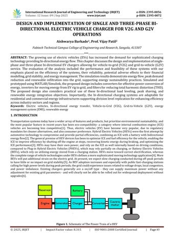
1. INTRODUCTION Transportation systems today have a wider array of features and products, but prioritize environmental sustainability, and the most popular feature in recent years has been eco-compatibility- a category where internal combustion engine (ICE) vehicles are becoming less competitive[1]. Thus, electric vehicles (EV) have become very popular, due to regulatory mandates for cleaner alternatives, and also consumer preference. Hybrid Electric Vehicles (HEVs) were the first attempt by automotive technology to compromise and provide partial efficiencies, combining an ICE with a battery with bidirectional energy flow[2]. The general premise of HEV devices has been to optimize ICE and fuel efficiency for the vehicle, enabling the ICE to improve efficiency by shutting off the engine at stops, recovering kinetic energy during braking, and optimizing the ICE performance[3]. HEVs may have their own power, and rely on the ICE as well internally based on driving conditions, compared to Plug-in Hybrid Electric Vehicles (PHEVs), which may rely partially on charging, or Battery Electric Vehicles (BEVs), which rely on utilizing energy stored from a charging station. HEVs move toward correct electrification, whereas the complete range of vehicle technologies under BEVs defines a more sophisticated moving technology application[4]. More BEVs will put additional strain on the electric grid. At present, we expect slow charging conducted during off-peak periods to have little or no impact on grid stability[5]. As BEV adoption increases and especially with public fast-charging stations calling for high power levels during peak periods, the grid could experience issues related to voltage drops, local congestion, and power imbalance. Existing chargers generally are a on/off type - they can supply maximum power without any adjustment for existing grid parameters - and will clearly not be able to be rolled out for widespread deployment without upgrades[6].
Figure 1. Schematic of The Power Train of a HEV © 2025, IRJET
|
Impact Factor value: 8.315
|
ISO 9001:2008 Certified Journal
|
Page 85