
International Research Journal of Engineering and Technology (IRJET) e-ISSN: 2395-0056
Volume: 12 Issue: 05 | May 2025 www.irjet.net p-ISSN: 2395-0072
International Research Journal of Engineering and Technology (IRJET) e-ISSN: 2395-0056
Volume: 12 Issue: 05 | May 2025 www.irjet.net p-ISSN: 2395-0072
Mr.R.GOPINATH1 , S.PREM KUMAR2 , P.NITHISH3, T.M.RAGUL KUMAR4
1Assistant Professor, Dept. of Mechanical Engg, Ganadipathy Tulsi’s Jain Engineering College, Tamilnadu, India 2,3,4 UG Student, Dept. of Mechanical Engg, Ganadipathy Tulsi’s Jain Engineering College, Tamilnadu, India
Abstract - The efficiency of slitter and rewinding machines relies heavily on the performance of their winding and unwinding shafts, with grip slip emerging as a key issue that compromises materialalignment, tensioncontrol,andoverall process stability. A widely used approach to reduce this problem is by increasing the number of shaft lugs to enhance grip; however, this often reduces the shaft’s structural strength, creating a critical trade-off between grip efficiency and mechanical integrity.
This study investigates enhancingtheperformanceof a pneumatic expansion shaft made from carbon steel AISI 1035 by redesigning it with an increased number of lugs and also study the shaft performance of existing model and proposedmodel usingFinite Element Analysistechniques.The mechanical response of the shaft under loading conditions is assessed by examining Von Mises Stress, Equivalent Strain, Displacement and Factor of safety. The analysis reveals that increased lug count enhances grip by improving frictional force distribution, but also leads to elevated stress concentrations and higher strain levels in critical shaft regions, which may accelerate fatigue failure.
Key Words: Slitterandrewindingmachines,GripSlip,Lug configurations,FEAAnalysis
Slittersandrewindersarecrucialmachinesusedacross multipleindustriestoprocesslargerollsofmaterialssuchas paper,film,textiles,andnonwovenfabrics.Thesemachines aredesignedtocutwiderollsintonarrowerwidths(slitting) andthenrewindthemintosmaller,moremanageablerolls (rewinding).Whetheryou'reinpackaging,printing,textiles orconverting,understandingthedifferenttypesofslitters andrewinders,theirkeycomponents,variousapplications andessentialmaintenancepracticesisvitalformaximizing operationalefficiency.
Inthisproject,SolidWorkssoftwarewasextensivelyused for3Dmodellinganddesign.SolidWorksisapowerfulCAD (Computer-Aided Design) software widely used in engineeringforcreatingdetailed3Dmodels,assemblies,and 2D drawings. It provided the necessary tools to design complex parts of the slitting rewinding machinewith high
precisionandallowedforefficientvisualization,simulation, and modification during the design phase. The software’s intuitiveinterfaceandrobustfeaturessupportedtheaccurate representation of shafts, frames, and other mechanical componentsessentialtotheproject.
In simple terms, analysis helps engineers predict how somethingwillperformbeforeactuallybuildingorusingit. Thiscanincludechecking:Willitbreakunderload,Willit deform too much, how heat or pressure will affect it. Engineers use mathematical models and simulation tools (likeFEA,CFD,etc.)toperformtheanalysis.It’sanessential stepinthedesignprocesstoensuresafety,performance,and reliability.Thisanalysisisusedtounderstandandoptimize thecomponentofapneumaticexpansionshaftunderload conditions to ensure uniform distribution load, which is essential for preventing grip slip improving the durability and efficiency of winding/unwinding processes. By using SolidWorks for simulation, engineers can visualize stress concentrations, identify weak points, and test design modificationsvirtuallybeforephysicalprototyping,saving bothtimeandcostwhileenhancingperformanceandsafety.
GovindolaVeeranderGoud,Dr.K.VijaykumarandDr.M. Sreedhar Reddy [1] This study evaluates the structural performanceofsolidandhollowaluminium-BLFcomposite shaftsthroughstaticanalysis,focusingondeformation,Von Misesstress,andweight.Resultsshowthatthesecomposites meet safety standards comparable to steel. While hollow shaftsoffer onlya modest weightreduction(1.16%),they remainpromisingforapplicationsrequiringahighstrengthto-weightratio.
Thirumurugaveera kumar Sundaram and Manivel MuralidaranVelumani[2]Thisprojectfocusesondeveloping anautomatedfilmrollcutterforroll-to-rollsystemsusedin printing, packaging, and converting industries. Precise tensioncontrolduringrewindingiscriticaltoavoidcommon defects. The cutter isdesignedusingadvanced3Dmodeling for visualization and optimization, with structural and thermal analyses ensuring its strength, durability, and industrialreliability.
International Research Journal of Engineering and Technology (IRJET) e-ISSN: 2395-0056
Volume: 12 Issue: 05 | May 2025 www.irjet.net p-ISSN: 2395-0072
Dr. Htay htay win and Dr. myint thein [3] Cipto Cipto, ChristianWullur,andHariyantoHariyanto[4]studiedashaft forameat-cuttingmachine.Theshaftis12mmindiameter and581mmlong.Itisdesignedtocarrya 5kgload.They usedAutodesksoftwareforfiniteelementanalysis(FEA).The analysisshowedtheshaftissafe.Theallowableshearstress (7.38kg/mm²)ishigherthantheappliedshearstress(5.62 kg/mm²).ThemaximumvonMisesstressis61.89MPa.The maximumdisplacementis0.07715mm.Thesafetyfactoris 3.34.Thismeanstheshaftisstrongenoughforthejob.
Grip slip in slitter and rewinding machines affects efficiencyandstability.Addingmoreshaftlugsimprovesgrip butweakenstheshaft.Tosolvethis:
1. Studygripslipmechanics,testlugchangesforgrip andstrength,andfindthebestdesign.
2. Modify the design to boost system performance, reliability,andefficiency.
3.1.
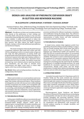
The pneumatic expansion shaft functions based on the controlled application of compressed air to achieve mechanicalexpansion,whichenablesittosecurelygripand rotate the core of a roll in slitter and rewinder machines. Internally,theshaftisequippedwithalongitudinallyplaced inflatablebladdermadefromrubberorsyntheticelastomers. Thisbladderishousedinsideacavityandconnectedtoan external air inlet valve. Upon injecting compressed air (typicallybetween3to5bar),thebladderinflatesuniformly along the shaft’s length. As it expands, it applies radial pressuretoaseriesofmechanicallugs,strips,orleavesthat are positioned in precisely machined slots on the shaft’s surface.Theselugsthenprotrudeoutwardandmakedirect contactwiththeinnerwallofthematerialcore,generating frictionalengagement.
Finite Element Analysis (FEA) is a computer-based methodusedtosimulateandanalysesphysicalbehaviorofa structure, component, or system under various conditions likeforce,heat,vibration,orfluidflow.
FEA is a numerical method that breaks down complex structures into smaller, simpler parts (called elements) to calculatehowtheywillrespondtoreal-worldphysicaleffects.
4.1 Volumetric Properties
Table – 1: VolumetricProperties
Mass 17.663kg
Volume 0.00225006m3
Density 7,850kg/m3
Weight 173.097N
4.2 Material Properties
AISI1035isawaterresistingcarbonsteelwhosewear resistanceandhardenabilityareincreasedbytheadditionof smallquantityofchromium.
Table – 2: MaterialProperties
Name AISI1035Steel(SS)
Modeltype
LinearElasticIsotropic
Yieldstrength 2.82685e+08N/m2
Tensilestrength 5.85e+08N/m2
Elasticmodulus: 2.05e+11N/m2
Poisson'sratio 0.29
Massdensity 7,850kg/m3
Shearmodulus 8e+10N/m2
Thermal 1.1e-05/Kelvin
4.3 Fixture
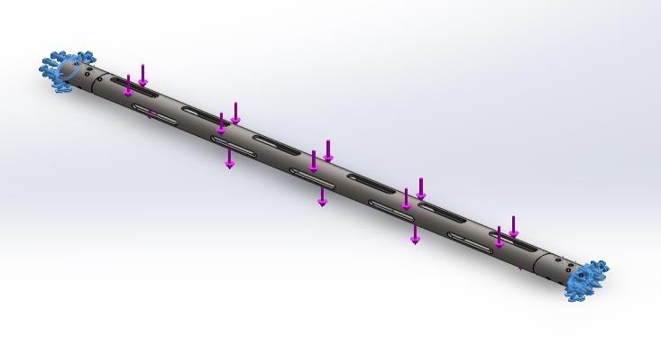
Fig – 4.1: Fixture
International Research Journal of Engineering and Technology (IRJET) e-ISSN: 2395-0056
Volume: 12 Issue: 05 | May 2025 www.irjet.net p-ISSN: 2395-0072
Toconstrainthemodelduringtheanalysis,fixtureswere applied using reference geometry. Specifically, two faces were fixed by referencing the Top Plane to replicate realworldboundaryconditions.Thefixturetypeusedwas"Use reference geometry", ensuring that the selected faces remained stationary throughout the simulation. No translationaldisplacementwasapplied,withthetranslation vector set to (0, 0, 0) in millimeter’s, indicating that all degreesoffreedomwerefullyrestrictedfortheselectedfaces
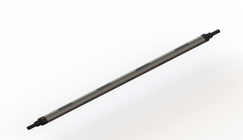
4.4 Load
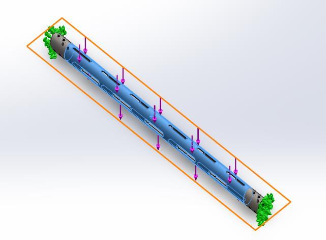
Fig – 5.6: Load
The mesh configuration,a single face was selected and referencedrelativetotheTopPlane.Aforceof-10,000Nwas appliedinthenegativeZ-direction,simulatingadownward axial load.Thisloadingconditionreflectsrealistic working scenarios and is essential for assessing the structural response of the component under the maximum expected load.
4.5 Mesh Details
Table -4: MeshDetails
Meshtype SolidMesh
MesherUsed Standardmesh
JacobianpointsforHighqualitymesh 16Points
ElementSize 7.84074mm
Tolerance 0.392037mm MeshQuality
4.6 Node in FEA
InFiniteElementAnalysis(FEA),anodeisaspecificpoint inthemodel'sgeometrywherecalculationsareperformed. Nodesserveasconnectionpointsbetweenelementsandare usedtodefinetheshapeandstructureofthemesh.Theyare crucial for applying boundary conditions (like loads or constraints)and forstoringresultssuchas displacements, temperatures,andstresses.
Table – 5: NodeInFea
TotalNodes 110251
TotalElements 56554
5. RESULT AND DISCUSSION
5.1 RESULT OF STANDARD SHAFT
5.5.1 Von Mises Stress
Inthissimulation,TheVonMisesStressachieveminimum stress value is 0.355N/mm2 (MPa) and maximum stress valueis141.520N/mm2(MPa).
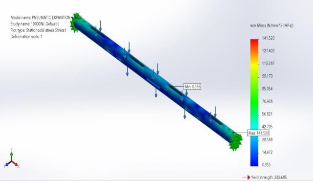
Fig - 6.5.1: VonMisesStress
5.5.2 Equivalent Strain
In this simulation, The Equivalent Strain achieve minimumstrainvalue2.618e-06andmaximumstrainvalue is4.839e-04.
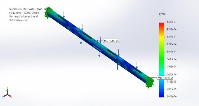
Fig - 6.5.2: EquivalentStrain
5.5.3 Displacement
During the simulation, The Resultant Displacement achieve minimum displacement value is 0.0mm and maximumdisplacementvalueis1.0mm.
International Research Journal of Engineering and Technology (IRJET) e-ISSN: 2395-0056
Volume: 12 Issue: 05 | May 2025 www.irjet.net p-ISSN: 2395-0072
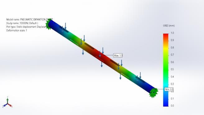
Fig -6.5.3: Displacement
5.5.4 Factor Of Safety
During the simulation, The Factor of Safety achieve minimumFactorofSafetyvalueis1.997e+00andmaximum FactorofSafetyvalueis7.955e+02.
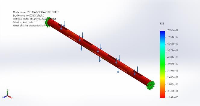
Fig - 6.5.4: FactorOfSafety
5.2 RESULT OF MODIFIED SHAFT
5.2.1 Von Mises Stress
Inthissimulation,TheVonMisesStressachieveminimum stressvalueis0.409N/mm2(MPa)andmaximumstressvalue is148.972N/mm2(MPa).
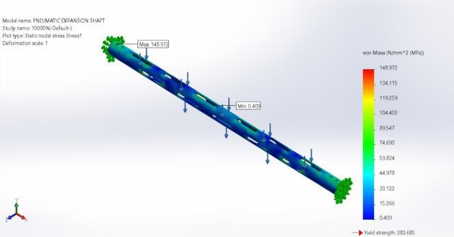
– 7.1: VonMisesStress
5.2.2 Equivalent Strain
In this simulation, The Equivalent Strain achieve minimumstrainvalue1.592e-06andmaximumstrainvalue is4.911e-04.
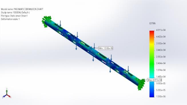
Fig - 7.2: EquivalentStrain
5.2.3 Displacement
During the simulation, The Resultant Displacement achieve minimum displacement value is 0.00mm and maximumdisplacementvalueis1.119mm.
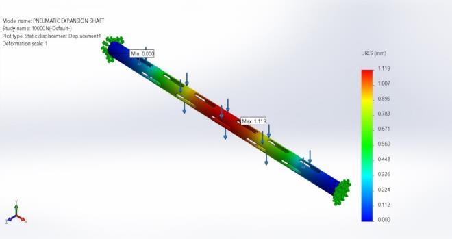
Fig - 7.3: Displacement
5.2.4 Factor Of Safety
During the simulation, The Factor of Safety achieve minimumFactorofSafetyvalueis1.898e+00andmaximum FactorofSafetyvalueis6.904e+02.
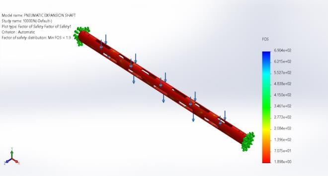
Fig - 7.4: FactorOfSafety
5.3 COMPARISON OF STATIC ANALYSIS RESULT
A comparison between the Standard Model and the ProjectModelbasedonvariousstructuralparameters.The ProjectModelincludesmorelugs,resultinginalargertotal
2025, IRJET | Impact Factor value: 8.315 | ISO 9001:2008
International Research Journal of Engineering and Technology (IRJET) e-ISSN: 2395-0056
Volume: 12 Issue: 05 | May 2025 www.irjet.net p-ISSN: 2395-0072
lugarea.Thisdesignmodificationleadstoaslightincreasein stress, strain, and displacement compared to the Standard Model. However, the factor of safety remains within acceptablelimits,indicatingthatthestructural integrityof theProjectModelismaintaineddespitethechanges.
Table – 6: ComparisonOfStaticAnalysisResult
mm2 NumberofLugs 14 22
Displacement
The study focused on enhancing the performance of a pneumaticexpansionshaftmadefromcarbonsteelAISI1035 by redesigning it with an increased number of lugs. In modifieddesignthenumberoflugshasbeenincreasedfrom 14to22,therebyexpandingthetotallugcontactareafrom 18,941.44 mm² to 29,764.46 mm². This change effectively improvesthegriponthecoreandminimizesthepossibilityof slipduringoperation.
Static analysiswas performed tocompare bothmodels underidenticalloadingconditions.Theresultsshowaslight increase in stress (from 141.52 MPa to 148.972 MPa) and strain (from 4.839×10⁻⁴ to 4.911×10⁻⁴), with a correspondingincreaseindisplacement(from0.959mmto 1.119 mm). Despite these increases, the modified model maintainsasatisfactoryfactorofsafetyof1.9,whichiswithin acceptabledesignlimits.
WewouldalsoextendourthankstoMr.D.Jagannath, Pavi Automation Pvt Ltd, Vellore for giving me us an excellentopportunitytoundergotheProjectwork.
[1] GovindolaveeranderGoud,Mr.N.Sidappa,Dr.K.Vijay kumar,Dr.M.SreedharReddy,“Designandanalysisof HollowandSolidshaft”InternationalResearchJournal of Engineering and Technology (IRJET), Volume-08, Issue-03,Mar2021.
[2] Thirumurugaveerakumar Sundaram and Manivel Muralidaran Velumani “Design and Analysis of Automated Film Roll Cutter”, 5th International
ConferenceonInnovativeProductDesignandIntelligent ManufacturingSystems(IPDIMS2023),July2024.
[3] Dr.HtayHtayWin,Dr.MyintThein,MgChanMyaeAung “Design and Performance Analysis of Potato Slicing Machine(ShaftDesignandRectangularCuttingBlade)” IRE1701544AUG2019
[4] Cipto Cipto, Klemens A Rahangmetan, Christian Wely Wullur,FaridSariman,andHariyantoHariyanto“Meat CuttingMachineShaftDesignandAnalysis”E3SWebof Conferences2021
[5] A. Inbasekaran, B. Vijaya Kumar, V. Sakthivel, G. Saravanan,A.Ramesh“Design&“ModificationofAeroShaft from Pneumatic to Mechanical” International ResearchJournalofEngineeringandTechnology(IRJET) Volume:03,Issue:04,Apr-2016
[6] Parth N. Raval, Pinank A. Patel “Expandable and CollapsibleWindingMandrel”InternationalJournalof Mechanical Engineering and Technology (IJMET) Volume5,Issue2,February(2014)


R.GOPINATH
[Assistant Professor, Dept. of Mechanical Engineering, Ganadipathy Tulsi’s Jain Engineering College, Tamilnadu, India]
S.PREM KUMAR
[UG Student, Dept. of Mechanical Engineering, Ganadipathy Tulsi’s Jain Engineering College, Tamilnadu,India]
P.NITHISH
[UG Student, Dept. of Mechanical Engineering, Ganadipathy Tulsi’s Jain Engineering College, Tamilnadu,India]
T.M.RAGUL KUMAR
[UG Student, Dept. of Mechanical Engineering, Ganadipathy Tulsi’s Jain Engineering College, Tamilnadu,India]