International Research Journal of Engineering and Technology (IRJET)
e-ISSN: 2395-0056
Volume: 12 Issue: 09 | Sep 2025
p-ISSN: 2395-0072
www.irjet.net
Assessment of Grid-Connected Wind Farm Performance under Variable Wind Conditions with DFIG Santosh Kumari Meena1, Khamma Kanwar2 and Dharmendra Meena 1,2 Assistant Professor, Department of Electrical Engineering MBM University, Jodhpur- 342001 3 Assistant Professor, Agriculture University, Jodhpur- 342001
---------------------------------------------------------------------***--------------------------------------------------------------------1.1 Wind Energy Conversion System Abstract - The worldwide consumption of electrical energy is increasing and there is gradually increased of demand on the power generation. Thus in accumulation to conventional power generation sources a various number of renewable energy sources are being connected into the power system .The wind turbine power generation unit is more economical and competitive of all the existing environmentally clean and safe renewable energy sources. However, wind electrical generation systems provide intermittent energy depending upon the wind regimes in the region. Therefore, any transient disturbance can result in changes in the voltage, current and power at various points of the integrated system. This paper shows simulation results for variation in wind speed obtained through transient analysis using generic wind turbine generation model. In the wind farm a doubly fed induction generator (DFIG) model is used. For showing the simulation of DFIG, MATLAB/SIMULINK software is used.
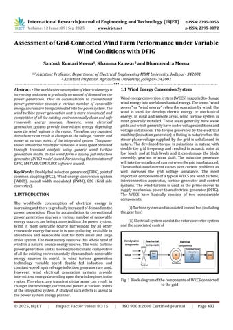
Wind energy conversion system (WECS) is applied to change wind energy into useful mechanical energy. The terms “wind power” or “wind energy” relate the operation by which the wind is used for develop electric energy or mechanical energy. In rural and remote areas, wind turbine system is most generally installed. These areas generally have weak grids and which generally have under voltage conditions and voltage unbalances. The torque generated by the electrical machine (induction generator) is fluting in nature when the stator phase voltage supplied by the grid is unbalanced in nature. The developed torque is pulsations in nature with double the grid frequency and resulted in acoustic noise at low levels and at high levels and it can damage the blade assembly, gearbox or rotor shaft. The induction generator will take the unbalanced current when the grid is unbalanced. These unbalanced current causes over current problems as well increases the grid voltage unbalance. The most important components of a typical WECS are wind turbine, interconnection apparatus, turbine generator and control systems. The wind-turbine is used as the prime-mover to supply mechanical power to an electrical generator (DFIG). The WECS have basically consists of two considerable components:
Key Words: Doubly fed induction generator (DFIG), point of common coupling (PCC), Wind energy conversion system (WECS), pulsed width modulated (PWM), GSC (Grid side converter).
1.INTRODUCTION The worldwide consumption of electrical energy is increasing and there is gradually increased of demand on the power generation. Thus in accumulation to conventional power generation sources a various number of renewable energy sources are being connected into the power system. Wind is most desirable source surrounded by all other renewable energy because it is non-polluting, available in abundance and reasonable cost for both small and large order system. The most satisfy resource this whole need of wind in a natural source energy source. The wind turbine power generation unit is more economical and competitive of all the existing environmentally clean and safe renewable energy sources in world. In wind turbine generation technology variable speed double fed induction and constant-speed squirrel-cage induction generators are used. However, wind electrical generation systems provide intermittent energy depending upon the wind regimes in the region. Therefore, any transient disturbance can result in changes in the voltage, current and power at various points of the integrated system. A study of such effects is useful to the power system energy planner.
© 2025, IRJET
|
Impact Factor value: 8.315
(i) Turbine system and associated control box (including the gear box) (ii) Electrical system consist the rotor converter system and the associated control
Fig. 1 Block diagram of the components of WECS connected to the grid
|
ISO 9001:2008 Certified Journal
|
Page 493