International Research Journal of Engineering and Technology (IRJET)
e-ISSN: 2395-0056
Volume: 13 Issue: 01 | Jan 2026
p-ISSN: 2395-0072
www.irjet.net
Analysis of Harmonics in Buck & Boost Converter Deenu Kumar Karsh1, Rupali Patel2, Rahul Manhar3, Prof . Vikas Chandra4 1,2,3,Dept of EEE Chouksey Engineering College Bilaspur (CG) 4 , Department of EEE, Chouksey engineering college bilaspur CG .India
---------------------------------------------------------------------***----------------------------------------------------------------------
Abstract- The voltage tracking of a de-de buck-boost
2. Boost Converter (Step-Up Converter)
converter is presented in this master report. The de-de Buck converter has three operating modes for tracking the output voltage. This master report includes DSpace-assisted open and closed loop control. When compared to other types of DC converters, the Buck-Boost converter offers a few advantages. The nonlinearity of the de-de Buck-Boost converter features, however, makes it challenging to manage with traditional techniques, like an open loop control system. This primary issue is addressed by developing a close loop control system with DSpace . The MATLAB-Simulink application is utilized to construct a simulation model in order to verify the efficiency of the proposed strategy. According to the simulation results, the suggested approach significantly improves control performance when compared to a con (Step-Down Converter) Visional converter.
When the switch is ON, the inductor stores energy from the input supply. When the switch is OFF, the inductor releases its energy, adding to the supply voltage –resulting in higher output voltage. Output Voltage - Vo Vin 1-D So, output voltage is greater than input voltage. Applications - Used in renewable energy systems (solar PV), battery-powered devices, and power factor correction circuits. 3. Buck Boost Converter
Introduction
A DC to DC converter which steps up or steps down the input voltage level" is what a buck-boost converter is. The duty ratio determines whether the input voltage level is stepped up or down. The ratio of the circuit's output voltage to its input voltage is known as the duty ratio or duty cycle. A controlled DC output is provided by a buck-bust converter.
DC-DC converters are electronic circuits that convert a DC voltage level into another. Among them, the Buck and Boost converters are the two most fundamental types. Buck Converter – Step down the input. Boost Converter - Steps up the input voltage.
The output voltage that is obtained while it is in buck mode is lower than the input applied voltage. The output current exceeds the input current in this mode. Nonetheless, the input and output powers are equal.
Both are switch-mode power supplies.(SMPS) that use highfrequency switching, energy storage elements (inductor and capacitor), and semiconductor switches (MOSFET, diode). 1.
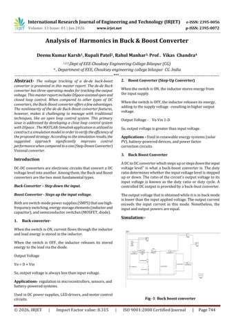
Simulation:-
Buck converter-
When the switch is ON, current flows through the inductor and load energy is stored in the inductor. When the switch is OFF, the inductor releases its stored energy to the load via the diode. Output Voltage Vo = D × Vin So, output voltage is always less than input voltage. Applications- regulation in microcontrollers, sensors, and battery-powered systems. Used in DC power supplies, LED drivers, and motor control circuits.
© 2026, IRJET
|
Impact Factor value: 8.315
Fig -1: Buck boost converter
|
ISO 9001:2008 Certified Journal
|
Page 744