
Advanced V2G and G2V Solutions for Microgrids with DC Fast Charging Architecture

Page 1


International Research Journal of Engineering and Technology (IRJET) e-ISSN: 2395-0056

Volume: 12 Issue: 11 | Nov 2025 www.irjet.net p-ISSN: 2395-0072

Advanced V2G and G2V Solutions for Microgrids with DC Fast Charging Architecture

1M. Tech student, Power System Analysis, Dept. of Electrical and Electronics Engineering, University BDT College of Engineering, Davangere, Karnataka, India.

2Professor, Dept. of Electrical and Electronics Engineering, University BDT College of Engineering, Davangere, Karnataka, India.

Abstract - The batteries of Electric Vehicles act as an energy storage device in microgrids. When there is an excessiveamount ofenergy, theystoreit(G2V,GridtoVehicle), and during the peak when there is an energy demand, they give it backto the grid(V2G, Vehicle to Grid). For this to work, a well-developedinfrastructure andmanagementmechanism must be set up. This paper introduces a Framework for creating a V2G and G2V system using level-3 fast charging for EVs in a microgrid. A test system for the micro-grid is built with a Charging station to connect the vehicles. The power flow in V2G and G2V is estimated by the simulations. The results show that EV batteries can actively control power in the microgrid using these modes. The charging station is designed to keep the grid current clean with minimal distortion, and the controller ensures stable DC bus voltage performance.
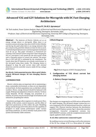
Key Words: Grid connected inverter, Micro-grid, Vehicleto-grid, Off-board charger, DC fast charging, Electric vehicle

1.INTRODUCTION

Electricvehiclesplayanimportantroleinmaintaininga clean,sustainableenvironment,astheyarenotdependent onfossilfuels.Astheirpopulationrose,sodidtheirvehicle numbers. Hence, energy demand should be balanced with supply.Widespreadadaptationofelectricvehicles.Tothese rising demands, DC-fast charging was presented as a solution.ACpowermaybestoredinhigh-levelbatteriesand utilizedforpropellingthevehicle.

Simulationpackagesallowengineerstostudypowerflow, stabilityofthesystem,control measures,andthe effect of high-level penetration of EVs within the grid. Modelling chargeanddischarge(G2V/V2G)allowsforthecapabilityof designers to study system performance under various operatingconditions,aswellasidentifyweakpointsinthe systemandidentifyviablesolutions.

2.Block

I. Configuration of V2G direct current fast charging station:

A. Battery Charger topology

Fig.2.1 BatteryChargerConfiguration

ThechargersareintegratedinanEVSEandareoff-boardfor DC rapid charging. The off-board charger system has as a corecomponentaDC-DCbidirectionalconverter,whichcan support V2G. Physical interface between the distribution grid(DC)andEVbatterysystem.Fig.2.1showstheconverter arrangement. Converter arrangement contains two IGBT/MOSFETswitches,withthecomplementary(control) signalsappliedtobothswitches

B. LCL filter and inverter connected to grid

Byenablingreversecurrentflowingaswellastheextension of the DC bus voltage of DC to a three-phase AC voltage

Diagram
Fig.2 BlockDiagramofDCFCChargingStation

International Research Journal of Engineering and Technology (IRJET) e-ISSN: 2395-0056

Volume: 12 Issue: 11 | Nov 2025 www.irjet.net p-ISSN: 2395-0072

(Fig.1),thegrid-connectedinverter(GCI)makesutilization oftheanti-paralleldiode’sswitchesfromeachlegpossible. The LCL filter is connected across the terminal of the inverterwiththe objective ofreducingtheharmonicsand producingpuresinusoidalcurrentandvoltage

II. CONTROL SYSTEM

A. Off-board charging control

Fig.1.2,PIcontrolschemeisemployedforcontrolcharging &discharginginthe(constantcurrentcontrol)methodfor the batterychargercircuit.Initially,thecontrollerverifies the current polarity signal to identify which mode of operation (charging or discharging) will be adhered to by comparingthereferencebatterycurrentwithzero.Afterthe modeselection,pulsesofSbuck/Sboostwillbegeneratedby contrastingthereferencecurrentwiththemeasuredcurrent. AnerrorwillbecorrectedthroughthePIcontroller.During charginganddrainingoperations,controloverSbuckwillbe disabled.

B. Control system of inverter

Fig.2.3 ControlSystemofInverter

•Onthed-axis,theouterloopcontrolsDCbusvoltage,and theinnerloopcontrolsactive(AC)current.

• On the q-axis, the outer loop controls AC voltage magnitudethroughregulatingreactivecurrent,onceagainto becontrolledbytheq-axis(innercurrentloop)

3 Circuit diagram

Thecircuitdiagramthatfollowsillustratestheconfiguration of different components in MATLAB Simulink using the Simulinklibrary.Theoverallcircuitdiagramforacharging stationutilizingDCchargingforvehicle-to-gridoperationis shown.

4.Results

The specifications of the charging station, along with the specific numbers,canbefoundintheAppendix.Thewind turbineoperatesatoptimumspeed,generating100kW(or the maximum available power) in ideal conditions. PV system test conditions (1000W/m2 sunlight and 25 °C), producing the highest power output of 50 kW. A 150-kW resistiveelectricalloadconnectedtoa480Vacsupply.The reactivecurrenttargetsetforGCIiszero;thus,thepower factor is one. In the simulation, both EV batteries are half chargedandhaveaSOCof50%.Onceeverythingstabilizes, boththeEV1andEV2batterieswillstarttotransferpower back and forth between the vehicles and the grid. Table I shows the current targets provided to battery chargers in EV1 and EV2, and the results observed in the following figures.Fig.4.1andFig.3.2provideinformationaboutthe batteries while EV1 is sending V2G, and EV2 is receiving G2V.

Table 4.1 Current,EVBatteries
Fig.2. 2 ConstantCurrentControl(Batterycharger)
Fig.3 CircuitDiagramofEVDCFCStation

International Research Journal of Engineering and Technology (IRJET) e-ISSN: 2395-0056

Volume: 12 Issue: 11 | Nov 2025 www.irjet.net p-ISSN: 2395-0072

4.2 Voltage,Current&SOCofEV2Battery(G2V)

GridpoweradaptstotheelectricityprovidedbyEVs.Fig.4.3, activepowergenerationbydifferentsystemcomponentsis presented.Anegativesignofgridpower(1to4)meansthe gridisreceivingpowerfromthecar.Thechangeofthegrid powersignat4ssuggeststhatthegridisnowprovidingthe electricitytochargethecarbattery;thus,demonstratingthe operationoftheV2G-G2Vsystem.ThezeronetpowerofPCC reflectsanidealpowerbalance.

Fig.4.4,innercurrentloopofcontrolisthenperformedby measuringthemodifiedd-axisreferencecurrent.

Fig. 4.5 shows current & voltage at PCC. reverse power is shown by both voltage & current being in phase for G2V operation&180degreesoutphasefortheV2Goperation

5.Conclusion

Thepaperdiscussesthedevelopmentandplanningsystem forEVstobothprovidepowerto,anddrawpowerfrom,a localareapowersystem(LAPS).TheLAPSoperatesusinga unique fast-charging method. A fast-charging station employing external charging ports and an inverter connectedtothemainelectricalgridenablesconnectionof EVswithintheoverallnetwork.Inuse,thedevelopedsystem controls the connection, allowing power to flow bidirectionallybetweenelectricvehiclesandtheelectrical network.Resultsfromtheevaluationsdemonstratethatflow issmoothinbothdirections,andpowerexportedfromthe electric vehicle system to the grid meets necessary standards. The controller that was developed operates effectivelyinthefaceofchangingconditions-maintaining voltagestabilityandfollowingthedesiredoutputofpower changes. This paper considers power management within

Fig. 4.1 Voltage, current & SOC of EV1Battery (V2G)
Fig.
Fig. 4.3 ActivePowerProfileofVariousComponentsin theSystem
Fig. 4.4 TrackingofReferenceCurrent(byInverter Controller)
Fig. 4.5 GridVoltage&InjectedGridCurrent(V2G&G2V)

International Research Journal of Engineering and Technology (IRJET) e-ISSN: 2395-0056

Volume: 12 Issue: 11 | Nov 2025 www.irjet.net p-ISSN: 2395-0072

thelocalaccountinggrid,buttheproposedsystemcouldbe deployedtosupportothertypesofoperationaswell,suchas reactivepowerandfrequencymanagement.Asitrelatesto future improvements, it is suggested to create a master controller to dispatch commands to the controllers connectedtotheelectricvehiclechargers.

6.Refrences

[1] Om P. Malik and Femina Mohammed Shakeel, “Vehicle-To-GridTechnologyinaMicro-gridUsing DCFastChargingArchitecture”,2025IEEECanadian ConferenceofElectricalandComputerEngineering

[2] Dr.G.SreeLakshmi,G.Divya,andG.Sravani,“V2G Transfer of energy to Various Applications”, 2024 E3SWebofConferences

[3] BrooksandM.A.Xue-ling,“Integrationofelectric drive vehicles with the power grid-a new application for vehicle batteries”, Battery ConferenceonApplicationsandAdvances,pp.239, 2024

[4] C. Shumei, L. Xiaofei, T. Dewen, Z. Qianfan and S. Liwei, “The construction and simulation of V2G system in micro-grid”, Proceedings of the InternationalConferenceonElectricalMachinesand Systems(ICEMS)2011,pp.1-4,2023.

[5] BakulVani,DevyaniChaturvedi,PreetiYadav,“Grid ManagementthroughVehicle-To-Grid-Technology”, International Journal of Recent Technology and Engineering (IJRTE), Volume-10 Issue-02, July 2021.

[6] Atharva Deshpande, Tushar Dongre, Pratik ChaudhariandShubhamBorse,“V2GandG2Vplugin and wireless charging integration in Vehicle Parking”, International Journal of Recent TechnologyandEngineering(IJRTE),

Turn static files into dynamic content formats.

Create a flipbook