
International Research Journal of Engineering and Technology (IRJET) e-ISSN:2395-0056
Volume: 12 Issue: 05 | May 2025 www.irjet.net p-ISSN:2395-0072
International Research Journal of Engineering and Technology (IRJET) e-ISSN:2395-0056
Volume: 12 Issue: 05 | May 2025 www.irjet.net p-ISSN:2395-0072
Viken B Bhagwagar1 , Siddharth A Sukhiyajiwala2 , Karan M Gandhi3 , Devam S Tamakuwala4
1 DepartmentofMechanicalEngineering,BhagwanMahavirCollegeofEngineeringTechnology,Surat,India
2 DepartmentofAutomobileEngineering,GIDCDegreeEngineeringCollege,Abrama,Navsari,India
3 DepartmentofAutomobileEngineering,GIDCDegreeEngineeringCollege,Abrama,Navsari,India
4 DepartmentofAutomobileEngineering,GIDCDegreeEngineeringCollege,Abrama,Navsari,India
Abstract - This review paper provides a comprehensive analysis of aerodynamic principles, drag reduction techniques, and instability effects in both heavy and light vehicles. It begins with fundamental airflow behaviour and governing equations, followed by the evolution of vehicle aerodynamics over the decades. A detailed comparisonofvariousvehicleshapes,frompassenger cars to race cars, highlights the aerodynamic tradeoffs between drag and downforce. Experimental and computational studies are examined to evaluate the effectiveness of drag-reducing devices such as rear diffusers, spoilers, vortex generators, and fairings. Specific focus is given to crosswind effects and instability risks, particularly in heavy trucks and high-speed race cars. Techniques like underbody optimization, spoiler angle tuning, and wake management are discussed for enhancing stability and performance. The review concludes by emphasizing the role of advanced CFD modeling and windtunneltestinginaerodynamicdevelopmentand the need for cost-effective design integration in commercialvehicles.
Keywords: Aerodynamic Drag, Drag Reduction, Computational Fluid Dynamics (CFD), Wind Tunnel Testing, Lift and Downforce, Rear Spoiler, Rear Diffuser, VortexGenerators(VGs),YawAngle,HeavyVehicles,Race Car Aerodynamics, Flow Separation, Pressure Distribution
Aerodynamics is a crucial aspect of modern automotive engineering, influencing key factors such as vehicle performance,fuel efficiency,safety,andstability.Itisthe study of air flow around objects and can be analyzed using three primary research approaches: theoretical, numerical, and experimental. Since the early days of automobile manufacturing, engineers have sought to improve vehicleaerodynamicsto enhance efficiency and
driving experience. However, with the increasing global emphasis on fuel economy, sustainability, and environmental regulations,theroleofaerodynamicsin automotive design has become more significant than ever[1].
A well-optimized aerodynamic design reduces air resistance (drag force), which is one of the most dominant forces acting against a moving vehicle. The drag force is generated due to the interaction between the car’s surface and the surrounding air, and its reduction can lead to substantial fuel savings. Studies indicate that for passenger vehicles traveling at highway speeds, nearly 50% of the total engine power is consumed to overcome aerodynamic drag [2]. Even a slight decrease in drag coefficient (Cd) can contribute to significant fuel efficiency improvements over long-distance travel, making aerodynamics a primary focus for automakers and researchers. In addition to fuel economy, reducing drag also leads to higher top speeds, improved acceleration, and better handling [3].
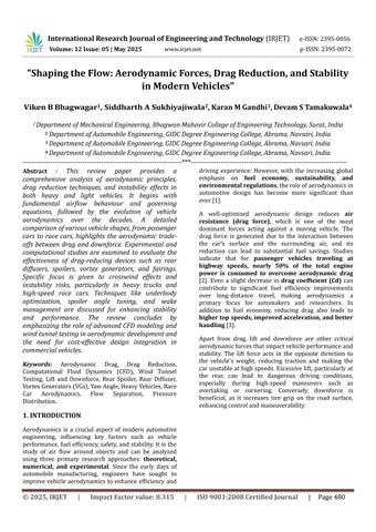
Apart from drag, lift and downforce are other critical aerodynamicforcesthatimpactvehicleperformanceand stability. The lift force acts in the opposite direction to the vehicle’s weight, reducing traction and making the carunstableathighspeeds.Excessivelift,particularlyat the rear, can lead to dangerous driving conditions, especially during high-speed maneuvers such as overtaking or cornering. Conversely, downforce is beneficial, as it increases tire grip on the road surface, enhancingcontrolandmaneuverability.
International Research Journal of Engineering and Technology (IRJET) e-ISSN:2395-0056
Volume: 12 Issue: 05 | May 2025 www.irjet.net p-ISSN:2395-0072
Fig. 1. Illustratesthe drag force acting on a race car,highlightingtheaerodynamicchallengesfacedathighspeedsand thenecessityofoptimizeddesignsolutions[5]
Modern vehicles, particularly sports cars, Formula 1 race cars, and high-performance road cars, use advanced aerodynamic devices such as spoilers, diffusers, and vortex generators to maximize downforce and minimize lift, ensuring better road adhesionandstability[4].
Inrecentdecades,advancementsin computational fluid dynamics (CFD), wind tunnel testing, and experimental aerodynamics have enabled more precise and efficient vehicle designs. The ability to simulate and optimize airflow in a virtual environment has reduced reliance on costly prototypes and has acceleratedthedevelopmentofaerodynamicallyefficient vehicles. Active aerodynamics, a cutting-edge technology that dynamically adjusts airflow based on real-time driving conditions, has gained traction in the automotive industry. This includes movable spoilers, adaptive air vents, and deployable underbody diffusers that automatically optimize airflow to balance dragreduction,cooling,anddownforcegeneration[5].
Beyondperformancebenefits,aerodynamicsalsoplaysa vitalrolein reducing vehicle emissions and improving environmental sustainability. The global automotive industry is under immense pressure to comply with strict government regulations regarding fuel consumption and carbon emissions. With the push toward electrification and alternative energy vehicles, aerodynamics has become even more critical. Electric vehicles (EVs), for instance, have lower energy reserves compared to traditional internal combustion engine (ICE) vehicles. To maximize their driving range, manufacturers must focus on minimizing aerodynamic losses. Many modern EVs, such as Tesla Model S and Lucid Air, incorporate highly optimized body designs
with smooth surfaces, closed grilles, and streamlined shapestoachieveexceptionallylowdragcoefficients[6].
Moreover, aerodynamics is not just limited to reducing drag but also contributes to noise reduction and passenger comfort Wind noise, which becomes more noticeable at higher speeds, is directly related to the aerodynamic shape of the vehicle. By refining body contours, sealing gaps, and optimizing side mirror placement, engineers can significantly reduce aerodynamic noise, leading to a quieter cabin experience[7].
In addition to the effects of aerodynamics on individual vehicles, aerodynamic forces also play a crucial role in traffic interactions, vehicle stability in crosswinds, and safety during high-speed maneuvers. When two vehicles pass each other at high speeds, the airflow disturbance and wake effects cancausesuddenforces, affecting vehicle stability. Studies have shown that trucks, buses, and large commercial vehicles create strong aerodynamic wakes that can influence the handling of nearby smaller vehicles, increasing the risk of accidents [8]. Understanding these aerodynamic interactions is essential for ensuring road safety and designing vehiclesthatcan withstand real-worlddriving conditions.
This review paper provides a comprehensive analysis of the role of aerodynamics in vehicle design,focusing on key aspects such as drag reduction, fuel efficiency, stability improvement, and the application of aerodynamic components. By synthesizing findings from experimental research, numerical simulations, and computational studies, this paper highlights the latest advancements in the field and explores innovative techniquesforoptimizingairflowaroundvehicles.
International Research Journal of Engineering and Technology (IRJET) e-ISSN:2395-0056
Volume: 12 Issue: 05 | May 2025 www.irjet.net p-ISSN:2395-0072
ComputationalFluidDynamics(CFD)employsnumerical methods and algorithms to analyze and solve fluid flow problems, particularly in the field of vehicle aerodynamics [9]. CFD serves as a crucial tool for understanding the governing equations of fluid motion, enabling engineers to simulate and optimize airflow patterns around automobiles [10-12]. According to a recentstudy bySoares[13],differentturbulencemodels integrated into CFD software play a vital role in determining aerodynamic characteristics in both passenger and commercial vehicles. Three widely utilized CFD approaches for airflow and aerodynamic simulations include Reynolds-Averaged Navier-Stokes (RANS), Unsteady RANS (URANS), and Large Eddy Simulation (LES) [14-19]. The RANS method solves steady-state, time-averaged Navier-Stokes equations, whereas URANS extends this approach to account for transient,unsteadyflows[20-22].Ontheotherhand,LES focuses on resolving spatially averaged Navier-Stokes equations by capturing large turbulence structures, makingitparticularlyeffectiveforcomplexaerodynamic assessments.
Among these approaches, Reynolds-Averaged NavierStokes (RANS) remains the most commonly applied CFD technique due to its relatively low computational cost and ability to generate reliable simulation results efficiently. The RANS method is based on time-averaged equations governing fluid motion, making it a preferred choice for modeling turbulent flows [23-25]. Since turbulence is inherently unpredictable and chaotic, the RANS framework provides a more manageable approximation by breaking down velocity and pressure intomeanandfluctuatingcomponents[26,27].However, due to the non-linear nature of the RANS equations, direct numerical solutions are impractical, necessitating theuseofturbulencemodels.
Various turbulence models have been developed within the RANS framework, including Standard k-ε, RNG k-ε, Realizable k-ε, Spalart-Allmaras, Standard k-ω, SST k-ω, and the Smagorinsky model.Eachofthesemodels hasdistinctadvantagesandlimitationsbasedonspecific aerodynamic applications. The k-ε model, while widely used, is known to be less accurate in near-wall regions compared to k-ω turbulence models [28]. This limitation arises due to the complexity of modeling the dissipation rate equation (ε), which requires additional wall treatment techniques for better accuracy in boundary-layer simulations, as discussed in research by Al-Saadi [28]. The k-ε model provides moderate accuracy in predicting drag forces but struggles to fully capture wake vortices and flow separation around a vehicle, making it less suitable for highly detailed
aerodynamic studies [13]. However, its efficiency in terms of computational resources requiring lower processingpower,memory,andsimulationtimemakesit acost-effectiveoption.
In contrast, the k-ω model delivers greater precision in drag predictions and aerodynamic flow characteristics, particularly in wake regions and near-wall boundary layers.However,italsopredictslargerwakevorticesand increased recirculation zones compared to the k-ε model,whichcanimpactoverall aerodynamic efficiency [13,29]. Despite its higher computational cost, the k-ω model isoftenpreferredforstudiesrequiringfine-tuned accuracy in boundary-layer interactions and flow separationanalysis.
Thefindingsfrommultiplestudiesinthisreviewindicate thatboth the k-ε and k-ω models are widely employed inCFD-basedvehicleaerodynamicsresearchduetotheir ability to simulateairflow characteristics effectively. The k-ε model is typically selected for simulations focusing on free-shear layers and wake field analysis, whereas the k-ω model is more suitable for investigations requiring higher accuracy in near-wall boundary-layer flows [30-33].
To gain a deeper understanding of established design approaches and functional requirements in vehicle aerodynamics, it is essential to thoroughly examine previous research. This section highlights studies that have analyzed the impact of different car body geometriesonaerodynamicforces.Informationhasbeen critically gathered from various sources, including research papers, theses, and online references, to provide a comprehensive review. Car body geometries are generally categorized into three main types: simplified shapes, fundamental car profiles, and production (commercial) vehicles
International Research Journal of Engineering and Technology (IRJET) e-ISSN:2395-0056
Volume: 12 Issue: 05 | May 2025 www.irjet.net p-ISSN:2395-0072
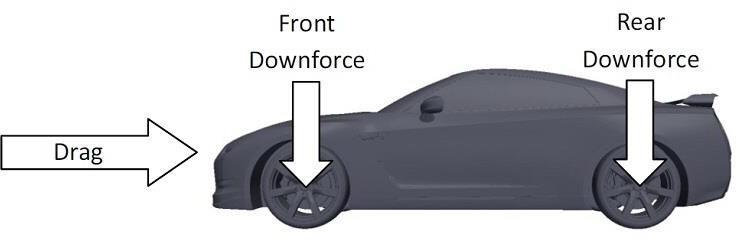
Reference models in this category play a crucial role in explaining the fundamental flow behavior around vehicles, aligning with the concept of "simplified" structures [42,34]. These simplified geometries are essentially highly abstracted models used for analysis, where all external components are excluded. One of the most widely recognized modelsfor aerodynamicstudies under this classification is the Ahmed model [35,36]. Thismodelcloselyresemblestheproportionsofatypical family car, as it is slightly larger, longer, and exhibits similar airflow characteristics. It features a blunt front end with rounded edges, a box-like midsection, and a sloped rear surface. A study conducted by Thabet and Thabit [37] utilized the Ahmed model witha slant angle (ϕ)of40°,
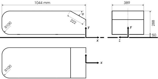
Fig. 2. TheAhmedmodel’sdimensions[37].
along with dimensions of 1044 mm in length (L), 288 mm in height (H), and 389 mm in width (W), as illustratedinFigure2.Ataninletvelocity(��)of40m/s, the corresponding drag coefficient (����) and lift coefficient (����) were found to be 0.323 and 0.0368, respectively. The k − ε turbulence model was chosen due to its efficient convergence properties. The Ahmed model is widely preferred in aerodynamic studies because of its simple geometry, well-defined geometric parameters, ease of airflow analysis, accessible drag coefficientdata,andextensiveCFDvalidation.
Another well-known simplified model is the Aerodynamics Studien Model (ASMO model), developed by the Daimler-Benz research division over a decade ago. This model was specifically designed to analyze low-drag shapes and to serve as a neutral reference body for CFD validation studies [38,39]. Its geometry consists of a square-back rear, smooth surfaces, a boat tail, and an underbody diffuser,with no pressure-induced boundary layer separation, as reported by Le Good and Garry [42]. Han incorporated the ASMO model in his study, using dimensions of 810 mm (L), 270 mm (H), and 290 mm (W) [40].Thestudy
applied an inlet velocity (��) of approximately 50 m/s, yielding drag and lift coefficient values of 0.165 and 0.125, respectively, using the Smagorinsky turbulence model. Researchers favor the ASMO model due to its smooth shape, which facilitates easier meshing without requiring extensive computational resources while still delivering accurate aerodynamic simulations, as shown inFigure3[40].
Fig. 3. TheAerodynamicsStudienModel(ASMOmodel) utilisedbyHan etal., [40]
Similarly, the Davis model is another simplified bluffbody geometry widely employed by researchers to analyze fundamental flow properties. Originally developedbyDavis,thismodelisvaluedforitsabilityto provide precise measurements of steady aerodynamic forces and moments under fixed yaw angles, assuming quasi-steady flow conditions [42]. Mansor et al. [41] utilizedtheDavismodelinhisresearch,withdimensions of 625 mm (L), 160 mm (H), and 225 mm (W), along with a rear angle of 20°, as depicted in Figure 4 [41]. Thestudyappliedaninletvelocity(��)of 40 m/s,witha Reynoldsnumberof 1.7×10⁶,basedonthemodellength. The drag coefficient (����) obtained was 0.228. For CFD simulations,the k – ε turbulence model wasselected,as it provided the closest agreement with pressure coefficientvaluescomparedtothe k − εmodel
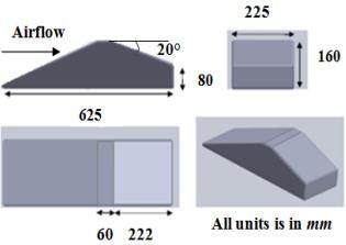
Fig. 4. TheDavismodelconfigurationsusedbyMansor et al., [41]
International Research Journal of Engineering and Technology (IRJET) e-ISSN:2395-0056
Volume: 12 Issue: 05 | May 2025 www.irjet.net p-ISSN:2395-0072
The geometriescategorized underthissection presenta moredefinedrepresentationofvehicleshapescompared to simplified models. These designs maintain the proportions of production vehicles while incorporating streamlined surfaces with minimal external components such as side mirrors. Fundamental vehicle shapes are primarily employed for research, validation, and experimental testing [43]. In this review, two primary models under this category are discussed: the Motor Industry Research Association (MIRA) model andthe TATA model
The MIRA concept car is among the most widely referenced concept vehicle models, cited in at least 20 academicstudies[42].It wasoriginallydevelopedbased on the design references of the Volkswagen 1600 and FIAT 124.Laietal.[44]implementedtheMIRAmodelin their research, developing its geometry using CATIA software.Themodeldimensionsinclude 520.625 mm in length (L), 203.125 mm in width (W), and 177.625 mm in height (H), as illustrated in Figure 5. The study configured an inlet velocity (v) of 30 m/s, defining the outletasapressureoutlet,withreferencepressuresetto atmospheric levels. The resulting drag coefficient (CD) from the analysis was 0.329. The k − ε turbulence model was selected for computational fluid dynamics (CFD) analysis due to its efficiency in predicting diverse airflowpatterns.PreviousstudiesindicatethattheMIRA model is advantageous foraerodynamic simulationsdue toits systematic scaling, simplified surface geometry, reduced computational demands, and suitability for numerical airflow predictions [42].
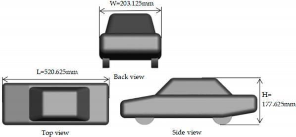
5. DimensionoftheMIRAmodelappliedinLaietal., [44]
The TATA model, originating from India, is a one-third scaled-down vehicle prototype that serves as a simplified base model by excluding external features such as side mirrors and spoilers. The TATA model comprises multiple subcategories, including the TATA Safari, TATA Nano, and TATA Indica.Aliteraturereview
identified research conducted by Samy et al. [53], who utilized the TATA Safari model for studying the SUV segment. The dimensions used in the study were 4655 mm (L) and 1855 mm (W) [53], with the windshield positioned at a 32° angle, located 100 mm from the front wheel centre (Figure6).Theresearchdetermined the drag coefficient (CD) and lift coefficient (CL) to be 0.620 and 0.099,respectively,usingan inlet velocity of 35 m/s and an ambient temperature of 34°C.The k − ε turbulence model was employed due to its ability to reduce computational load while maintaining accurate aerodynamic predictions. The study concluded that this model effectively optimizes computational efficiency whileprovidingreliableaerodynamicinsights.
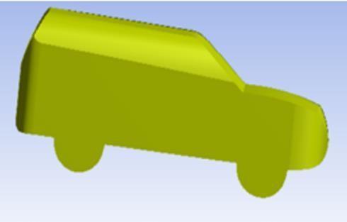
In another study, Ansari [54] utilized the TATA Indica model, where the vehicle’s geometry was developed through blending 2D and 3D curves to generate a realistic visual representation. Classified as an Asegment compact car, the model exhibited a drag coefficient (CD) of 0.841, with an inlet velocity of 19.44 m/s. The k − ε turbulence model was implemented to evaluate the airflow field due to its efficiency in dissipating turbulence energy and ensuring short computational times (Figure7).
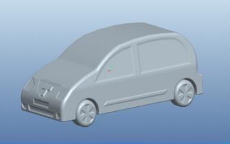
Furthermore,Dattaetal.[45]conductedresearchusinga generic car model, stripped of external components to simplify the CFD process. Figure 8 presents the
International Research Journal of Engineering and Technology (IRJET) e-ISSN:2395-0056
Volume: 12 Issue: 05 | May 2025 www.irjet.net p-ISSN:2395-0072
dimensionsofthe base model vehicle, which measures approximately 4 meters (L), 2 meters (W), and 1.8 meters (H). To enhance computational feasibility, the design was downscaled to a 1:10 ratio. The study applied an inlet velocity of 27.78 m/s (perpendicular to the boundary) andobtained drag (CD) and lift (CL
coefficients of 0.3385 and 0.2531,respectively.The k − ε turbulence model wasselected forCFD analysis,asit provides robust performance, reduced computational effort,andiswidelyadoptedbyautomotiveengineersfor aerodynamicassessments[45].
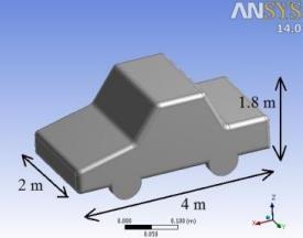
8. Full-scalebasemodelcarutilisedbyDattaetal., [45]
Swift Dzire: Dias et al. [55] analyzed this model by simplifying certain features (e.g., exhaust and door handles) to optimize computational efficiency while retaining side mirrors. The vehicle dimensions were 3995 mm (L), 1555 mm (W), and 1695 mm (H), with an inlet velocity of 40 m/s and a drag coefficient (����) of 0.375
Fig. 9. The Swift Dzire model applied in computational analysisbyDiasetal.,[55]
KIA Pride: Saleh and Ali [58] conducted a study by removing components like side mirrors and grilles to streamline simulation. With dimensions of 3935 mm (L), 1605 mm (W), and 1455 mm (H), this model recorded a drag coefficient (����) of 0.355 at an inlet velocity of 30 m/s. The k − ε turbulence model was appliedforefficienthandlingoffree-shearlayerflows.
Fig. 10. ThebasemodelfortheKIAprideusedin simulationbySalehandAli[43]
Resnick Model: Le Good et al. [50] introduced this model to study vehicle aerodynamics, particularly for autonomous vehicle technology. Designed as a highridingcoupe/SUV,ithaddimensionsof 267 mm (L), 108 mm (W), and 98 mm (H). With an inlet velocity of 40 m/s, the drag coefficient (����) was determined to be 0.27. The k − ε turbulence model was used for its reliability in simulating wall-bounded flows and freeshear layer conditions with minimal pressure gradients [45].
Fig. 11. Full-scalespecificationoftheResnickmodel appliedinLeGood’setal.,[50]simulation
Hybrid Electric Vehicle (HEV): Ramasamy et al. [49] conducted a CFD study on this model, which was originally developed by Drayton and Coombs [51]. The HEV design was simplified by removing several external elements except for the tires to minimize simulation
International Research Journal of Engineering and Technology (IRJET) e-ISSN:2395-0056
Volume: 12 Issue: 05 | May 2025 www.irjet.net p-ISSN:2395-0072
complexity.Themodelhaddimensionsof 4110 mm (L), 1655 mm (W), and 1360 mm (H), with a 2380 mm wheelbase.Thevelocityinletvariedbetween 11.11 m/s and 30.56 m/s, producing dragcoefficient(����)values of 0.312 to 0.356. The k − ε turbulence model was applied due to its suitability for analyzing diverse fluid dynamics and its balance between accuracy and computationalefficiency[52].
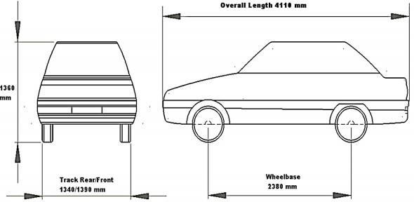
Fig. 12. The Hybrid Electric Vehicle (HEV) car model utilizedinCFDsimulationbyRamasamyetal.,[49]
Ingeneral,the drag force onavehicleisinfluencedbyits body profile, surface characteristics, and airflow interactions. When air flows over the vehicle surface, flow separation occurs at sharp edges, leading to pressure variations between the front and rear of the vehicle[56].Thisphenomenoncreatesturbulenceinthe wake region, increasing aerodynamic drag and reducing overallefficiency.
One of the major contributors to drag is profile drag, which consists of pressure drag and surface friction drag, contributing 80-90% of total aerodynamic resistance [56]. To optimize vehicle aerodynamics, minimizing wake turbulence at the rear is crucial. Ventilation base integration isoneapproachtoreduce rear-endturbulencebymodifyingairflowpatterns.
The ventilation base system consists of two converging hollow tubes positioned under the vehicle floor.Thesetubesfunctionby injecting low-velocity air into the wake region,reducingpressuredifferencesand mitigating drag [56]. As shown in Figure 13, the vent basesystemisintegratedwithoutaffectingthestructural designofthevehicle.
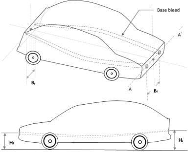
Fig.13.Basicconnectionofventilationinthecar model[57].
Toassesstheeffectivenessoftheventilationbasesystem, laboratory tests were conducted by optimizing the followingkeyparameters:
Bf: Distancebetweenthetwoconverginghollowtubesat thefront
Br: Distancebetweentheventilationpipesattherear
Hf: Heightofthefrontventilationbasefromtheground
Hr: Heightoftherearventilationbasefromtheground
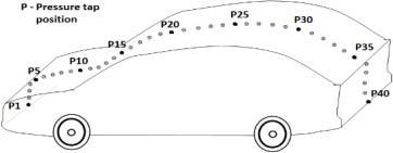
Fig.14.Schematicdrawingofthecarmodelwith pressurevalves[57].
Pressure distribution across the vehicle surface was measured with and without the ventilation base system using 40 pressure valves (P1 to P40) placed along the vehicle’s centreline. These pressure valves were connected to a Digital Scanner Array (DSA) for precisedatacollection,asillustratedinFigure14[57].
The results demonstrated that incorporating a ventilation base system reduces rear-end turbulence, leading to improved aerodynamics, lower drag coefficients,andenhancedvehicleefficiency.
International Research Journal of Engineering and Technology (IRJET) e-ISSN:2395-0056
Volume: 12 Issue: 05 | May 2025 www.irjet.net p-ISSN:2395-0072
To assess the effectiveness of external attachments in minimizing aerodynamic drag, researchers conducted wind tunnel experiments using a scale truck model. Aerodynamic drag (D) is influenced by the frontal area
CarModel Classification (Type)
(A), drag coefficient (Cd), air density (ρ\rhoρ), and vehiclespeed(VVV),asdefinedbytheequation:
Duringtesting,variouswindspeedsandyawangleswere examined while sensors recorded drag, lift, and side forces, along with yaw, pitch, and roll moments. The baseline truck model exhibited the highest drag coefficient, whereas incorporating side skirts, front skirts,andclosingthetractor-trailergapresultedinthe
Table 1: Summaryofliteraturereviewsbasedonvariouscargeometriesmodel
Author InletVelocity,�� /ReynoldsNumber
Simple Bodies (AhmedModel) Thabet and Thabit [37]
SimpleBodies (ASMOModel)
Han et al., [40]
SimpleBodies (DavisModel) Mansor et al.,[41]
BasicCar Shapes (MIRA Model)
Lai et al , [44]
BasicCar Shapes(TATA SafariModel)
BasicCar Shapes (TATA IndicaModel)
BasicCar Shapes (Base GenericModel)
Production (Series) Cars (SwiftDzireModel)
Samy et al.,[53]
Datta et al.,[45]
Dias et al., [55] �� =40��/��
Production (Series) Cars (KIA PrideModel)
Ali[43]
Production (Series) Cars (ResnickModel)
Production (Series) Cars (Hybrid Electric VehicleModel)
LeGood et al.,[50]
Ramasamy et al.,[49] �������� = 1111��/�� �������� =3056��/��
Loads
(1044mm× 288mm× 389mm)
= 0125 (810mm× 270mm× 290mm)
(625mm× 160mm× 225mm)
= 0329 (520625 mm× 177625mm ×203.125 mm)
= 0099 (L =4655 mm× W = 1855mm)
Software
CCM+ Software
Turbulence model Ansys Fluent Software
= 0841 Imported3D sketches �� �� Turbulence model Ansys Fluent Software
02531 (4000mm× 1800mm× 2000mm)
= 0375 (3995mm× 1695mm× 1555mm)
(3935mm× 1455mm× 1605mm)
= 0270 (267mm× 98mm× 108mm)
0312
(4110mm× 1360mm× 1655mm)
Turbulence model Ansys Fluent Software
�� Turbulence model
Software
�� Turbulence model Ansys Fluent Software
�� Turbulence model Ansys Fluent Software
�� Turbulence model Cosmos FloWorkstm software
International Research Journal of Engineering and Technology (IRJET) e-ISSN:2395-0056
Volume: 12 Issue: 05 | May 2025 www.irjet.net p-ISSN:2395-0072
lowest drag. Maximum drag reduction of 26% was achieved throughthesemodifications[58].
Furtherstudiesemployingwindtunnelandcomputationalfluid dynamics (CFD) methods analyzed the effects of underbody
airflow on a 15-ton truck and a 40-foot trailer. Different aerodynamicconfigurationswereexamined,includingstandard side skirts and new designs incorporating additional inclined flap panels. Results showed that a 45-degree inclined flap reduceddragby5.3%forthe15-tontruckand4.7%forthe40foot trailer compared to conventional skirts. A skirting design with a 60-degree folded inner panel achieved reductions of 5.1% and 5.0%, respectively. Large Eddy Simulations (LES) confirmed a 5.4% drag reduction for the flap-type side skirt, closelymatchingwindtunnelresults[59].
To enhance truck fuelefficiency, three primary strategies were explored: energy management, adaptive aerodynamics, and Human-MachineInterface(HMI).Thestudiedtruck,along-haul tractor-semitrailer, was modified with electrically controlled actuatorssuchasaradiatorshutter,electricfans,awaterpump, an additional generator, a controllable thermostat, and an electrohydraulic power steering system. Active aerodynamic componentswerealsointegratedtooptimizefuelconsumption. CFD simulations demonstrated that side deflectors improved fuel savings by 0.3–1.5%, a controllable radiator shutter contributed0.3%,andaroofdeflectorofferedpotentialgainsof upto2%[60].
Experiments also investigated the influence of rear flaps on drag reduction without requiring major structural changes. Various flap shapes elliptical, rectangular, and triangular were tested at different mounting angles. The best drag reduction occurred at a 50-degree mounting angle, with elliptical flaps yielding the greatesteffect.Maximumdrag reduction of11.1% was observed using elliptical flaps compared to the baseline model. Even perforated elliptical flaps outperformed other designs, demonstrating that an optimized aerodynamic shape enhancesefficiency[61].
Truck aerodynamics in South Asia were also analyzed, revealing that many deflectors in Bangladesh and Pakistan are designed for aesthetic appeal rather than efficiency. Compared to an optimized streamlined deflector, which reduced drag by 13%,traditionalBangladeshideflectorsincreaseddragby33%, while Pakistani designs worsened drag by 56% [62]. Another study investigated the optimal placement of truck fairings, comparing three configurations: (1) a truck without a fairing, (2) a truck with an old fairing design, and (3) a truck with a modifiedfairingpositioned500mmforward.Pressurecontour analysis revealed that the repositioned fairing significantly reduced pressure on the truck's glass window by 75.45 Pa and improved airflow separation between thetractor andtrailer,leadingtolowerdragforces[63].
Another effective drag reduction method involved the useofvortexgenerators(VGs).Astudyusinga1:20scale tractor-trailer model tested counter-rotating backwardfacing vane-type VGs of two sizes (VG1 and VG2) placed
atthefrontandrearofthetrailer.ThelargerVG(VG2)at thefrontreducedwakevortexformationby12.9%,while placement at the rear resulted in a 5.8% reduction [64].
Windtunneltestsalsoexploredplasmavortexgenerator actuators positioned on the A-pillar. At a yaw angle of 9 degrees,dragreductionofupto20%wasachieved[65].
Additionally, convoy rolling effects on aerodynamic resistance were studied using CFD simulations. Four truck models were arranged in a convoy with a 3-meter spacing, which is considered safe in real-world traffic.
The leading truck experienced the highest drag, while subsequent trucks benefited from reduced aerodynamic resistance. The second truck had the greatest pressure reduction of 75%, whereas the remaining trucks saw smaller yet significant reductions. However, a potential downsidewasreducedairflowtoheatexchangers,which maynecessitatecoolingsystemoptimization[67].
Overall, substantial drag reduction can be attained through external modifications such as side skirts, rear flaps, vortex generators, and optimized fairing placement. The most effective approach involvedclosing gaps on heavy vehicles, although practical implementation challenges remain. Further research is needed to refine convoy spacing, determine the optimal VGsizeand placement,and enhanceactive aerodynamic systemsforimprovedefficiency[66].
Aerodynamic enhancements, such as rear spoilers, significantly impact the drag reduction of hatchback models,ultimatelyimprovingfueleconomy.Windtunnel experiments on a scaled car model analyzed airflow at the rear, comparing conditions with and without a spoiler.Resultsdemonstratedthatacarequippedwitha spoiler exhibited lower pressure variation and reduced drag force, with its pressure coefficient proving more effectiveathighspeeds[68].
Computational studies using Reynolds-Averaged NavierStokes (RANS) simulations investigated the influence of rear roof spoilers on hatchback aerodynamics. Findings revealed that a simple strip-type spoiler efficiently reduced drag at pitch angles between 0° and 5°, though drag increased at higher angles. The spoiler mitigates drag primarily by controlling airflow acceleration at the leading edge of the sloped section and preventing the formation of longitudinal vortices. However, real-world vehicle motion, including pitching effects, was not consideredinthisstudy[69].
International Research Journal of Engineering and Technology (IRJET) e-ISSN:2395-0056
Volume: 12 Issue: 05 | May 2025 www.irjet.net p-ISSN:2395-0072
Racecaraerodynamicshavealsobeenexaminedthrough wind tunnel experiments and CFD simulations. A comparative study assessed the aerodynamic characteristicsofa racecar wing, obtaining resultsfrom STAR-CCM CFD software and wind tunnel tests. The relative error between the two methods was 4%. When thesideslipangleremainedconstant,nocorrelationwas observed between aerodynamic forces, moments, and speed. However, as the sideslip angle increased, aerodynamic force and torque coefficients exhibited distinctvariationpatterns[70].
Braking performance in race cars, particularly during cornering, is as crucial as acceleration. The NITK Racing FormulaStudentCarintegratedamechanicalactuatorto convertbrakepedal motion into rotational movement of the rear wing’s aerofoil blade. Testing various angles of attack led to an optimized wing design that improved aerodynamic braking by generating controlled drag. Using the equation CD=2sin2αC_D = 2 \sin^2\alphaCD =2sin2α,maximumdragwasestimatedbasedonaerofoil thickness and position, with values ranging from 30° to 80°[71].
Further aerodynamic research focused on the rear wing designs of Formula 1 (F1) cars. A 2D CFD model, incorporating k-ε, k-ω, and k-kl-ω turbulence models, analyzed airflow around an F1 wing at 43 m/s, the average speed during corner entry. The study evaluated different flap wing configurations and Drag Reduction System (DRS) effects. Results indicated that thicker aerofoil designs reduced drag, while larger flaps increaseddownforce.However, whenDRS wasactivated, smallerflapseffectivelyreduceddrag,makingthemmore suitableforcircuitswithlongstraightsections[72].
Thecombinedeffectsofunderbody,front,andrearwings on open-wheel race car aerodynamics were also investigated using CFD. The study analyzed four vehicle configurations: (A) a flat underbody, (B) an underbody with a rear diffuser, (C) a combination of a rear diffuser withtwo-elementfrontandrearwings,and(D)asimilar setup but with three-element wings. Diffusers improved downforce without significantly increasing drag, while wingsenhanceddownforceatthecostofincreaseddrag. Despite similar aerodynamic effects, the three-element wing (model D) was preferred due to its lighter weight. Wool tuft flow visualization confirmed CFD findings, ensuringaerodynamicaccuracy[73].
AnotherstudyutilizedCFDtooptimizetheaerodynamics ofaproductioncarmodelbytestingvariousreardiffuser angles. Wind tunnel validation using the Ahmed body confirmed that CFD accurately predicted aerodynamic coefficients. The best diffuser angle was found to be 8°, as it reduced lift coefficient (CLC_LCL) with a negligible increase in drag coefficient (CDC_DCD). Beyond this
angle, drag increased significantly despite further reductionsinlift[74].
The first prototype of a Formula SAE race car from the University of Perugia underwent aerodynamic refinementusing windtunnel andCFDanalysis.Initially, only the nose section was examined to compare experimental and numerical drag results. In the second phase, two complete race cars (RB11.1_a and RB11.1_B) were evaluated numerically, revealing that individual design modifications significantly influenced drag and downforce. The wind tunnel test yielded a CDC_DCD of 0.46, while CFD simulations produced a value of 0.43 [75].
The ARTeC EMo-C race car, a hybrid between Formulatype and urban cars, was designed for maximum fuel efficiency.ItsaerodynamicswereassessedusingCFDand wind tunnel tests. A CATIA-generated car model was analyzedinFLUENTat13.9m/s,whilea1:10scalewind tunnel model was tested at 10–30 m/s. CFD resultsunderestimated drag compared to wind tunnel findings, primarily due to the omission of skin friction. Tire aerodynamics contributed significantly to drag, accounting for a 25.7% increase in profile drag coefficient.Atanaveragespeedof40km/h,aerodynamic drag accounted for no more than 20% of engine power consumption[76].
Aerodynamic studies have also examined side mirror designs using ANSYS Fluent. Three mirror shapes were testedatspeedsof17m/sand33m/s.Thesemi-circular mirror design exhibited the least drag and pressure coefficient variation, reducing surface oscillations and minimizingimageblurringcausedbyaerodynamicforces [77].
Advancements in vehicle aerodynamics have led to modernpassengercarsachievinglowerdragcoefficients (down to 0.3). Internal engine bay airflow contributes approximately10%oftotalaerodynamicdrag.Astudyin Tokai University’s wind tunnel examined 48 different grille configurations, varying inlet opening size, radiator placement, and engine orientation. Findings revealed that increased inlet size generally raised drag and front lift while reducing rear lift. In models with a radiator, dragincreased withlargerinletheights, thoughposition hadminimaleffect[78].
Innovative drag reduction methods include air jet wheel deflectors, which create an air curtain ahead of the wheel, diverting airflow and lowering aerodynamic resistance. As the jet speed increases, stagnation pressure on the tire surface decreases, leading to drag reduction. A study found that aligning jet speed with vehicle velocity achieved a 6.4% drag reduction. This system also enhances brake cooling by directing airflow towardsthecallipers[79].
International Research Journal of Engineering and Technology (IRJET) e-ISSN:2395-0056
Volume: 12 Issue: 05 | May 2025 www.irjet.net p-ISSN:2395-0072
Comparisons of grooved and slick tires revealed that grooved tires generate greater aerodynamic resistance due to pressure differentials near the contact patch. Numericalstudies,validatedbywindtunnel testsatPSA Peugeot Citroen, confirmed that slick tires experience greater pressure drops, leading to higher profile drag [80].
Various external aerodynamic modifications, including spoilers, diffusers, and optimized mirror designs, effectively reduce drag in passenger cars. Spoilers mitigaterearturbulenceandincreasedownforce,though improperattackanglescanleadtoincreaseddrag.Active spoilers with adjustable actuation provide the best results by generating additional downforce only when necessary[68–73].Diffusersprimarilymanageliftrather than reducing drag [74]. A summary of different drag reductiontechniquesisprovidedinTable2
Table2:Comparingthedifferentmethodsusedbydifferentpaperstoreduceaerodynamicdrag
Vehicletype Description
Semi-trailer truck [58][60]
Truck-trailer [59][64][66]
Useof side-skirts and differentfairings
Different side skirts DifferenttypesofVGs
Truck[61–63] Different types of flaps and fairings are tested
Hatchback car [68][69]
Drag reduction by rearspoiler
Racecar[70][76] Characteristics of the wing, diffuser and underbody were tested.
Passenger car [77][78]
Design of side view mirrors and engine roomflow
Advantages
Dragwasreduced
Maximum drag reduction for 45o inclined skirt VG reducesdrag.
Elliptical flaps and aerodynamic deflectors placed forward, reduced drag
The spoiler reduced drag
Model equipped with front and rear wing and diffuser had the bestresult
Semi-circle shape mirrorwerebest
5.1 In heavy vehicles
Crosswinds pose a significant rollover hazard for heavy vehicles,increasingtherisktopassengers[89],[90].Ina flat-ground scenario, the impact of low and mean turbulent conditions becomes more pronounced at higher yaw angles. The simulated vertical wind speeds play a crucial role in determining both the roll moment andlateralforcesactingon thevehicle.Atthewindward roof edge, the vertical component of airflow is most affectedatthedetachmentpoint.Assuctionovertheroof intensifies, this detachment point shifts upward, leading to a greater upward-directed vertical force. More
Complex nature of design
ground clearance is reduced
The real size model hastobetested
The VG position and designmustaccurate
Tests done were limited Drag reduction is possible by using thesemethods
Proper angle must be maintained for the spoiler
Angle of attack must be varied to adopt to thesituation
Tests were limited 10%dragcanbefrom engineroom
Spoilers can both create and reduce drag
Actuated wings adapt torequiredsituations
More mirror shapes and engine layouts canbetested
detailed insights into crosswind effects are available in [99–].
The lateral force and roll moment admittance functions followasimilartrend,bothdecreasingfrom1to0asthe non-dimensional frequency increases from 0 to ∞. Meanwhile, the admittance function for vertical force beginsat1whenthenon-dimensionalfrequencyis0and reachesitspeakwhenthefrequencyisequalto1.Unlike lateral forces, vertical forces are primarily influenced by the pressure distribution above and below the vehicle ratherthanbythelateralsurfacepressure.
Whenheavyvehiclesoperateinenvironmentsotherthan flat terrain, such as embankments, single and double viaducts, and situations involving upward or downward
International Research Journal of Engineering and Technology (IRJET) e-ISSN:2395-0056
Volume: 12 Issue: 05 | May 2025 www.irjet.net p-ISSN:2395-0072
wind flows, the rollover risk varies. Among all yaw angles, flat-ground scenarios present the least risk. The highestrolloverthreatoccursonsingleviaductsatlarger yaw angles (α > 50°) and on embankments and double viaducts at smaller yaw angles. Additionally, on viaducts and embankments, lateral aerodynamic forces and roll moments tend to decrease as the wind transitions from anupward toa downward flow,particularlyathigh yaw angles. A notable difference in yaw moments between viaductandembankmentconditions wasobserved, with both scenarios having similar amplitude but opposite signs[24].
A moving vehicle model was validated using an experimental setup involving two prisms in relative motionundercrosswindconditions.Thenumericalwind tunnel results were compared with experimental data from previous studies to ensure accuracy. Due to the asymmetrical geometry of real trucks, variations in side forceandyawmomentnearpeakvalueswereevident.As a vehicle approaches and exits the wake of a structure, the crosswind-induced lateral force and yaw moment fluctuate,witha30%reductioninlateralforceoccurring when the vehicle is positioned in the center of the wake [25].
A comparison of different trailer designs revealed that tank trailers, with their smooth surfaces, experienced lower lateral forces. In contrast, trailers with larger side areas exposed to wind were more prone to rollover due tohigherlateralforcesactingonthem.Theyawmoment wasfoundtobeprimarilyinfluencedbythelengthofthe vehicle, whereas the lateral force admittance function was mainly dependent on the side area exposed to the wind. Larger side areas resulted in smaller amplitude variations in the lateral force admittance function, emphasizing the role of aerodynamic design in minimizingrolloverrisks[24],[25].
Vehicletype
Theadditionofrearspoilersonhatchbackvehicleshelps minimize turbulence at the rear while increasing downforce, leading to improved stability [11]. Computational Fluid Dynamics (CFD) simulations using Reynolds-Averaged Navier-Stokes (RANS) equations have been utilized to study the impact of rear roof spoilers on aerodynamic drag. Results suggest that a simplestrip-typespoilerprovidesbeneficialeffectswhen setatapitchangleof0°to5°[12].
Informula-styleracecars,therearwingplaysakeyrole in generating significant downforce for stability during cornering while minimizing drag on straight paths. Actuators adjust the wing angle to optimize performance, with the ideal angle in straight-line travel depending on the design, whereas maximum brakingefficiency isachieved when the wing is perpendicularto airflow[14],[15]
Open-wheel race cars equipped with front and rear wings, as well as a diffuser, perform better than those withouttheseaerodynamiccomponentsorwithonlyone ofthem[16].
Experiments on rear diffusers at different angles revealed that an 8° angle was the most effective. At this setting,thecoefficientoflift(CL)decreasedby -0.01968, while the coefficient of drag(CD)increased onlyslightly (+0.0019)comparedtoamodelwithoutadiffuser.When the diffuser angle exceeded 8°, CD values rose. Since the wake region behind the vehicle significantly contributes topositivelift,reducingitanddirectingairflowupwards through a rear diffuser was effective in lowering lift and increasing downforce [17]. Further studies demonstrated that modifying or removing individual aerodynamic components directly impacts drag and downforce[18].
Table 3: Comparingthemethodsusedtocontroltheaerodynamicinstability
Description
Boxfishdesign[35] Bio-mimicry of yellow
box fish of Ostraciidae fishfamily
New tail shape of car [36]
Upgrading the tailshape of the car to improveairflow
HorasMesinUSU[37] The new design was compared with respect tofordfiesta
Car with expanded windshield[38]
Expandingwindshieldto study the aerodynamic effects
Advantages
CD= 0073ataReynolds numbers equivalent to 100 km/h of inflow velocity
Drag was reduced by 45% and lift was decreased
The CD and CL were found to be lesser than fordfiesta
The drag coefficient was diminishedby885%
Limitations
Shape of the vehicle is different from conventionalvehicles
Only the tail shape has beenstudied
The ford fiesta had better aerodynamic characteristics
Expanding the front windshield of the car impacts the streamlined dragandwindcurrent
Remarks
The CD valuesare lesser than the values of normalvehicles
Other parts also have to beconsidered
The design failed to be better than any productioncar.
The change on the vehicle did not have any majorimpact.
International Research Journal of Engineering and Technology (IRJET) e-ISSN:2395-0056
Volume: 12 Issue: 05 | May 2025 www.irjet.net p-ISSN:2395-0072
Theinfluenceoftiresonliftwasalsoexamined,showing thattheliftcoefficientwithouttireswas-0.053,butwith tires, it increased to 0.339 [19]. Among various aerodynamic modifications, the underbody rear diffuser plays a vital role in controlling airflow. The impact of diffuser angles was studied without additional components like separators or end plates. CFD simulationswereperformedonanoptimizedmodelwith diffuser angles set at 0°, 3°, 6°, 9.8°, and 12°, with the initial model featuring a 9.8° angle. Results showed that increasingthediffuserangleledtosignificantchangesin underbody airflow and wake, affecting pressure distribution. Initially, the aerodynamic drag coefficient decreased butstartedincreasingbeyonda certainangle, while the lift coefficient continued to decrease [26]. The effectiveness of rear spoilers is also dependent on their heightandinclinationangle.
Asmallerattackangleresultsingownforce.Aspoilerset at a 12° inclination was found to be the most effective, but it caused a 1.56% increase in CD compared to a 4° inclined spoiler. Maintaining a low CL is essential for betterhandlingathighspeeds[27].Acomparativestudy on a Formula SAE race car’s aerodynamic performance was conducted using FLUENT software under two conditions: without a wing package and with a wing package at various angles of attack. In the absence of wings,highstaticpressurewasobservedonthevehicle’s front body, tires, and the driver’s chest and head, while large vortices behind the driver created negative pressure.Whenequippedwithwings,theaerodynamic-
Vehicletype Description
setup significantly increased downforce, improving performance in dynamic conditions. An 8° rear wing angle contributed approximately 65% of the vehicle’s totaldownforce,providingcrucialdesignparametersfor aerodynamicenhancement[28].
The front wing of a race car was also examined under ground effect conditions. Simulations revealed that net downforce increased in this scenario. The lift coefficient (CL) showed a 20% increase when the attack angle changed from 0° to 120°, but beyond 120°, CL dropped by about 45%, indicating a potential stall between 120° and 160°. Additionally, CD increased by around 50% up to 120° but remained stable afterward [29]. Airfoil designreferencesweretakenfrom[70],[71].
In automobiles, instability is largely caused by positive lift, which can be countered by generating negative lift (downforce) [11], [12], [14], [19], [26]–[29]. Downforce canbeachievedusingreardiffusers[16],[17],[26],rear spoilers
[11], [12], [14]–[16], [27]–[29], and front spoilers [16], [19], [29]. While some aerodynamic techniques from race cars can be adapted to passenger vehicles, production costs may make them impractical for mass adoption. Table 2 presents a comparison of different instabilitycontrolmethods.
Advantages Limitations
Truck[24][25] Effects of crosswind whichcausesrollover Smooth windward surface can reduce the chancesofrollover
Hatchbackcar[11][12] Using spoiler to create down-force
Racecar[14]–[19],[28],[29]
Passenger car [17][26], [27]
The wing, diffuser and underbodyweretested
The effects of a rear diffuserandspoileron airflowwerestudied
Angle of 0 to 5 degrees createhighdown-force
8 to16 degree attack angle provided enough down-force
Angle of 8o of diffuser had sufficient downforce. Spoiler of 12 inclinationwasideal
The surroundings effect the force acting on the vehicles
If the attack angle is too highitcancreatedrag
Further increase in angle can also increase drag. The tiresproducedlift
Beyond 8 degree angle of diffuser the drag increases The 12 degree spoiler increasesCD
Remarks
Vehicle design has to be improved to avoid rollover
Downforceshouldbe createdwithoutdrag.
Actuated spoiler creates drag when required and reduces whennotrequired
The lift can be reducedbutitshould notincreasethedrag.
International Research Journal of Engineering and Technology (IRJET) e-ISSN:2395-0056
Volume: 12 Issue: 05 | May 2025 www.irjet.net p-ISSN:2395-0072
This review paper provides an extensive analysis of vehicle aerodynamics, focusing on aerodynamic forces, drag reduction techniques, and instability control methods forboth heavy and light vehicles.The study emphasizes how airflow interactions, vehicle body shape, and external modifications significantly impact aerodynamic drag, stability, and overall efficiency
The discussion on aerodynamic forces highlights how pressure drag, friction drag, and wake turbulence contribute to aerodynamic resistance, affecting vehicle performance. Flow separation at sharp edges creates turbulence,increasingdrag,particularlyattherearofthe vehicle. Solutions such as ventilation base systems, which inject low-velocity air into the wake region, have proven effective in reducing pressure differences and mitigatingdrag.
In drag reduction techniques, various methods have beenexploredforbothheavyandlightvehicles.In heavy vehicles,externalattachmentssuchas side skirts, front skirts, vortex generators, and rear flaps have demonstrated significant drag reduction in wind tunnel andCFDstudies. Active aerodynamic elements,suchas radiator shutters and adaptive deflectors,haveshown potential for further efficiency gains. Additionally, convoy rolling effects highlight how strategic truck formations can reduce drag for following vehicles. In light vehicles,aerodynamic enhancementssuchas rear spoilers, underbody diffusers, and optimized mirror designs contribute to reducing drag and improving fuel efficiency.Studieson race car aerodynamics revealthat adjustable wings and optimized diffuser angles playa crucial role in enhancing downforce while minimizing dragduringhigh-speedconditions.
The impact of aerodynamic instability was also examined, particularly in crosswind conditions that pose significant risks for heavy vehicles. Yaw moments andlateralforcesincreaserolloverhazards,especiallyon viaducts and embankments,wherewinddirectionand vehicle geometry playcritical roles.Comparativestudies show that trailer designs with smooth surfaces experience lower lateral forces, reducing rollover risks. For light vehicles, rear spoilers, diffusers, and optimized airfoil designs help counteract positive lift, improving vehicle stability at high speeds. Motorsports applications further demonstrate that ground effect aerodynamics, optimized wing angles, and controlled airflow management are essential for maintaining stabilityduringcorneringandacceleration.
Overall, the review highlights the importance of aerodynamic optimization in improving vehicle fuel
efficiency, safety, and performance.The integration of active aerodynamic systems, adaptive airflow control, and real-time drag reduction technologies represents the next step in achieving practical aerodynamic solutions for both commercial and highperformance vehicles. While cost and structural constraints limit widespread adoption, future research should focus on developing scalable aerodynamic solutions that can be integrated into everyday vehicles without compromising efficiency, stability, or affordability
[1] Ruhollah Behravan, Mira Alam Mehdi, "Numericalstudyofthecombinedeffectsofrear spoiler and curvature of lateral surfaces on the lift and traction force on the sedan", Journal of Modares Mechanical Engineering, Volume 18, Number2,2016,Page305-313.
[2] Wolf-Heinrich, H. “Aerodynamics of Road Vehicles”, Fluid Mechanics to Vehicle Engineering,4thEdition,1998
[3] Javad Marzban Rad and Hamid Reza Khalili. "Study of car aerodynamics and its effect on car fuel consumption". Journal of Mechanical Engineering,73,1390,pp.43-51.
[4] Kourosh Goodarzi, Vahid Jandaghi Shahi, Mohammad Hassan Shojaei-Fard. "Study and simulation of vehicle aerodynamics phenomenon when passing another vehicle (overtaking maneuver)", Journal of Modares Mechanical Engineering, Volume 11, Number 1, 2012,pp.29-40.
[5] HamidrezaThamahdiandMajidAbbasAliZadeh. "DesignandProposalofanAerodynamicLoadto Reduce Vehicle Drag", Second National Conference on Mechanical Systems and Industrial Innovations, Ahvaz, Iran, February 2014.
[6] Noger, C., Regardin, C., Sze´che´nyi, E. “Investigation of the transient aerodynamic phenomenaassociatedwithpassingmaneuvers”, Journal of Fluids and Structures 21, 2010, pp. 231–241.
[7] Mohammad Hassan Javarshkian, Reza Shasteh Sadafian, Ayram Azarkhvish. "Numerical and experimental study of aerodynamic forces on a basic vehicle model", Journal of the Faculty of Engineering,No.1,2010,pp.50-64.
[8] Shankar, G., Devaradjane G. “Experimental and Computational Analysis on Aerodynamic BehaviorofaCar Model with Vortex Generators atDifferentYawAngles”.JournalofAppliedFluid Mechanics11(1),2018.pp.285-295.
[9] Abobaker, Mostafa, Abdulhafid M. Elfaghi, and Sogair Addeep. "Numerical Study of Wind-
International Research Journal of Engineering and Technology (IRJET) e-ISSN:2395-0056
Volume: 12 Issue: 05 | May 2025 www.irjet.net p-ISSN:2395-0072
[10] Bhaskaran, Rajesh, and Lance Collins. "Introduction to CFD basics." Cornell UniversitySibley School of Mechanical and Aerospace Engineering (2002):1-21.
[11] Wang, Bin, You-Lin Xu, Le-Dong Zhu, and YongLe Li. "Crosswind effect studies on road vehicle passing by bridge tower using computational fluid dynamics." Engineering Applications of Computational Fluid Mechanics 8, no. 3 (2014): 330-344.
Tunnel Wall Effects on Lift and Drag Characteristics of NACA 0012 Airfoil." CFD Letters 12,no.11(2020):72-82 50-62.
[12] Versteeg, Henk Kaarle, and Weeratunge Malalasekera. An introduction to computational fluiddynamics:the finitevolumemethod.Pearson Education,2007.
[13] Soares, Renan Francisco. "Drag of road cars: cost-effective CFD setup, proposal of an aerodynamic concept and case studies." UniversidadeFederaldeUberlândia (2015).
[14] Salim, Salim Mohamed, and Kian Chuan Ong. "Performance of RANS, URANS and LES in the prediction of airflow and pollutant dispersion." In IAENG Transactions on Engineering Technologies, pp. 263-274. Springer, Dordrecht, 2013.
[15] Jehad,D.G.,G.A.Hashim,A.K.Zarzoor,andC.S. Nor Azwadi. "Numerical study of turbulent flow over backward- facing step with different turbulence models." Journal of Advanced ResearchDesign 4,no.1(2015):20-27.
[16] Karthik, T. S. D., and F. Durst. "Turbulence models and their applications." 10th Indo German Winter Academy (2011):1-52.
[17] Baker,Chris,Federico Cheli, Alexander Orellano, Nicolas Paradot, Carsten Proppe, and Daniele Rocchi. "Cross-wind effects on road and rail vehicles." Vehicle System Dynamics 47, no. 8 (2009):983-1022.
[18] Jain, Shubham, Nekkanti Sitaram, and Sriram Krishnaswamy. "Effect of Reynolds number on aerodynamics of airfoil with Gurney flap." InternationalJournalofRotatingMachinery 2015 (2015).
[19] Fiumara, Alessandro, Nicolas Gourdain, Vincent Chapin, Julien Senter, and Yannick Bury. "Numerical and experimental analysis of the flowaroundatwo-elementwingsailatReynolds number 0.53 × 10⁶." International Journal of HeatandFluidFlow 62(2016):538-551.
[20] Biadgo,AsressMulugeta,Aleksandar Simonovic, Jelena Svorcan, and Slobodan Stupar. "Aerodynamiccharacteristicsofhighspeedtrain under turbulent cross winds: A numerical investigation using unsteady-RANS method." FMETransactions 42,no.1(2014):10-18.
[21] Yusuf, Siti Nurul Akmal, Yutaka Asako, Nor Azwadi Che Sidik, Saiful Bahri Mohamed, and Wan Mohd Arif Aziz Japar. "A Short Review on RANSTurbulenceModels." CFDLetters 12,no.11 (2020):83-96.
[22] Ismail,NoorIswadi,MahamadHisyamMahamad Basri,HazimSharudin,ZurriatiMohdAli,Ahmad Aliff Ahmad Shariffuddin, and Nik Muhammad Izwan Nik Mohd Kamel. "Investigations of Lift andDragPerformancesonNeo-PteroMicroUAV Models." Journal of Advanced Research in Fluid MechanicsandThermalSciences 84,no.2(2021):
[23] Altinisik,Armagan,EmreKutukceken,andHabib Umur. "Experimental and numerical aerodynamic analysis of a passenger car: Influence of the blockage ratio on drag coefficient." Journal of Fluids Engineering 137, no.8(2015).
[24] Cogan, Donavan. "The aerodynamic design and development of an urban concept vehicle through CFD analysis." PhD diss., Cape Peninsula UniversityofTechnology,2016.
[25] Sosnowski, Marcin, Renata Gnatowska, Karolina Grabowska,JarosławKrzywanski,andArkadiusz Jamrozik."Numericalanalysisofflowinbuilding arrangement: Computational domain discretization." Applied Sciences 9,no. 5 (2019): 941.
[26] Çengel, Yunus, A., and John M. Cimbala. Fluid Mechanics: Fundamentals And Applications (First Edition).McGrawHillHigherEducation,2006.
[27] Ishak, Izuan Amin, Mohamed Sukri Mat Ali, Fadhilah Mohd Sakri, Fathul Hakim Zulkifli, Nofrizalidris Darlis, Rahmah Mahmudin, Shaiful Fadzil Zainal Abidin, Muhamad Asri Azizul, SyabillahSulaiman,NorAfzanizamSamiran,and Amir Khalid. "Aerodynamic Characteristics Around a Generic Train Moving on Different Embankments under the Influence of Crosswind." Journal of Advanced Research in Fluid Mechanics and Thermal Sciences 61, no. 1 (2019):106-128.
[28] Al-Saadi, Ahmed Ali Shakir. "Analysis of Novel Techniques of Drag Reduction and Stability Increase for Sport Utility Vehicles using Computational Fluid Dynamics." PhD diss., UniversityofLeeds,2019.
[29] Yakhot, V., S. A. Orszag, Siva Thangam, T. B. Gatski, and C. G. Speziale. "Development of turbulence models for shear flows by a double expansion technique." Physics of Fluids A: Fluid Dynamics 4,no.7(1992):1510-1520.
[30] Poroseva, Svetlana, and Gianluca Iaccarino. "Simulation of Separated Flows with the KEpsilonModel."In APSDivisionofFluidDynamics MeetingAbstracts,vol.54,pp.EE-007.2001.
International Research Journal of Engineering and Technology (IRJET) e-ISSN:2395-0056
Volume: 12 Issue: 05 | May 2025 www.irjet.net p-ISSN:2395-0072
[31] Hassan, Saud. "Aerodynamics investigation of rear vehicle (Backlight angle)." PhD diss., Doctoraldissertation,TeessideUniversity,2014.
[32] Abd Halim, M.A., N.A. R.Nik Mohd, M.N.Mohd Nasir, and M. N. Dahalan. "The evaluation of k-ε and k-ω turbulence models in modelling flows and performance of s-shaped diffuser." International Journal of Automotive and Mechanical Engineering 15, no. 2 (2018): 51615177.
[33] Mohamed, Wan Mazlina Wan, Nirresh Prabu Ravindran, and Parvathy Rajendran. "A CFD Simulation on the Performance of Slotted Propeller Design for Various Airfoil Configurations." CFD Letters 13, no. 3 (2021): 43-57.
[34] Mazlan, Mohamad Zahid, Fazila Mohd Zawawi, Teeab Tahzib, Kamarulafizam Ismail, and Syahrullail Samion. "Performance Analysis of Highway Wind Turbine Enhanced with Wind GuideVanesUsingtheTaguchiMethod." CFDLetters 13,no.3(2021):25-42.
[35] Hughes, Thomas. "CFD Study of Flow over a Simplified Car Using Different Turbulence Models." PhDdiss.,UniversityofDerby,2018.
[36] Mukuvare,Arnold."CFDPredictionofSeparation FlowoveraSimplifiedCarModel." PhD diss., The UniversityofWestofEnglandBristol,2018.
[37] Thabet, Senan, and Thabit H. Thabit. "CFD simulation of the air flow around a car model (Ahmed body)." International Journal of Scientific and Research Publications 8, no. 7 (2018):517-525.
[38] Tsubokura, Makoto, Toshio Kobayashi, Takuji Nakashima, Takahide Nouzawa, Takaki Nakamura, Huilai Zhang, Keiji Onishi, and Nobuyuki Oshima. "Computational visualization of unsteady flow around vehicles using high performance computing." Computers & Fluids
[39] Perzon, Sven, and Lars Davidson. "On transient modeling of the flow around vehicles using the Reynolds equation." In International Conference onAppliedComputational FluidDynamics (ACFD) BeijingChina,pp.720-727.2000.
[40] Han, Shan Ling, Zhi Yong Li, Jin Bin Li, and Ru Xing Yu. "Simulation Research on Aerodynamic Characteristics of Vehicle under Steady CrosswindBasedonXFlow."In AppliedMechanics and Materials, vol.494,pp. 138-141.Trans Tech PublicationsLtd,2014.
[41] Mansor, S., N. A. R. Nik Mohd, and C. W. Chung. "ValidationofCFDModelingandSimulationofa Simplified Automotive Model." In Applied Mechanics and Materials, vol. 735, pp. 319-325. TransTechPublicationsLtd,2015.
[42] LeGood,GeoffreyM.,andKevinP.Garry."Onthe use of reference models in automotive aerodynamics." SAETechnicalPapers (2004).
[43] Saleh, Z. M., and A. H. Ali. "Numerical Investigation of Drag Reduction Techniques in a CarModel."In IOP Conference Series: Materials Science and Engineering, vol. 671, no. 1, p. 012160. IOP Publishing, 2020.
[44] Lai,Chenguang,HangFu,BoHu,ZhiweiLing,and Li Jiang. "Aerodynamic Drag Reduction and Optimization of MIRA Model Based on Plasma Actuator." In Actuators, vol. 9, no. 3, p. 64. Multidisciplinary Digital Publishing Institute, 2020.
[45] Datta, Basudev, Vaibhav Goel, Shivam Garg, and InderpreetSingh."StudyofVariousPassiveDrag Reduction Techniques on External Vehicle Aerodynamics Performance: CFD Based Approach." International Research Journal of Engineering and Technology (IRJET) 6, no. 5 (2019):1851-1871.
[46] Osorio, David Eduardo Aljure. "Aerodynamic analysis of complex geometries using CFD." PhD diss., Universitat Politècnica de Catalunya (UPC), 2017.
[47] Zhang, Chunhui, Charles Patrick Bounds, Lee Foster, and Mesbah Uddin. "Turbulence modeling effects on the CFD predictions of flow over a detailed full-scale sedan vehicle." Fluids 4, no. 3 (2019): 148.
[48] Anish, A., P. G. Suthen, and M. K. Viju. "Modelling and analysis of a car for reducing aerodynamic forces."International Journal of Engineering Trends and Technology 47,(2017)
[49] Ramasamy,D.,K.Mohanesan,K.Kadirgama,M.M. Noor,andM.M.Rahman."Hybridelectricvehicle carbodydraganalysisusingcomputationalfluid dynamics." International Journal of Automotive and Mechanical Engineering 14 (2017): 44964507.
[50] LeGood,Geoffrey,MaxResnick,PeterBoardman, and Brian Clough. "An Investigation of AerodynamicEffectsof Body Morphing for Passenger Cars in Close-Proximity." Fluids 6, no. 2 (2021): 64.
[51] Drayton, Spencer, and Mark Coombs. Proton (Haynes Service and Repair Manual Series) HaynesPublishing,1997.
[52] Mingliang, Wu, Mingzhe Rong, Fei Yang, Yi Wu, JianzhongZhu,andChunpingNiu."AComparative Study of k-epsilon Turbulence Model in DC CircuitBreaker."In 20thInternationalConference onGasDischargesandtheirApplications,p.47-50. 2014.
International Research Journal of Engineering and Technology (IRJET) e-ISSN:2395-0056
Volume: 12 Issue: 05 | May 2025 www.irjet.net p-ISSN:2395-0072
[53] Samy, G. S., S. Thirumalai Kumaran, M. Uthayakumar, M. Sivasubramanian, and Krishna Bhagavathi Sankar. "Numerical analysis of drag and lift coefficient of a Sport Utility Vehicle (SUV)." In Journal of Physics: Conference Series, vol.1276,no.1,p.012013.IOPPublishing,2019.
[54] Ansari, Abdul Razzaque. "CFD Analysis of Aerodynamic Design of Tata Indica Car." International Journal of Mechanical Engineering andTechnology 8,no.3(2017):344-355.
[55] Dias, Gavin, Nisha R. Tiwari, Joju John Varghese, and Graham Koyeerath. "Aerodynamic Analysis ofaCarforReducingDragForce." IOSRJournalof Mechanical and Civil Engineering (IOSR-JMCE) 13,no.3(2016):114-118.
[56] Lamond, A., Kenned, J. J.andStickland,M. T. "An Investigation into Unsteady BaseBleed for Drag ReductioninBluff Two-BoxSUVs".An European Automotive Simulation Conference, EASC, Department of Mechanical Engineering, UniversityofStrathclyde,2010.pp.6–7,UK.
[57] Sivaraj,G.,Parammasivam,K.M.,andSuganya,G. “Reduction of Aerodynamic Drag Force for Reducing Fuel Consumption in Road Vehicle using Basebleed”. Journal of Applied Fluid Mechanics,Vol.11,No.6,2018.pp.1489-1495.
[58] Chowdhury, H., Moria, H., Ali, A., Khan, I., Alam, F., Watkins, S. 2013. A study on aerodynamic drag of a semi-trailer truck, Procedia Eng, 56, 201–205.
[59] Hwang, B.G. 2016. Reduction of drag in heavy vehicles with two different types of advanced side skirts, J. Wind Eng. Ind. Aerodyn., 155, 36–46.
[60] Lindgarde,O.,Soderman,M.,Tenstam,A.,Feng,L. 2016.OptimalCompleteVehicleControlforFuel Efficiency,Transp.Res.Procedia,14,1087–1096.
[61] A.Altaf,A.,Omar,A.,Asrar,W.2014.Passivedrag reduction of square back road vehicles, J. Wind Eng.Ind.Aerodyn.,134,30–43.
[62] Chowdhury, H., Loganathan, B., Mustary, I., Moria, H., Alam, F. 2017. Effect of Various DeflectorsonDragReductionforTrucks,Energy Procedia,110,561–566.
[63] Chen, J., Deng, N., Li, Y., Liang, C., Lin, B. 2017. CFD-based optimization of truck fairing structure, IOP Conf. Ser. Earth Environ. Sci., 61(012160),0–7.
[64] Lo, K.H., Kontis, K. 2016. Flow characteristics over a tractor-trailer model with and without vane-type vortex generator installed, J. Wind Eng.Ind.Aerodyn.,159,110–122.
[65] Vernet, J.A., Orlu, R., David, S., Elofsson, P., Alfredsson,P.H.2018.PlasmaStreamwiseVortex Generators for Flow Separation Control on Trucks,FlowTurbul.Combust,100,1101–1109.
[66] Kuwik,B.S.,Tabacjar,C.M.,Lee,S.2018.TheDrag ReducingEffectofVortexGeneratorsonTractorTrailer Vehicles, Am. Inst. Aeronaut. Astronaut. Aerosp.Sci.Meet.,1–8.
[67] Iozsa, D., Stan, C., Ilea, L. 2017. Study on the Influence of the Convoy Rolling over Aerodynamic Resistance, IOP Conf. Ser. Mater. Sci.Eng.,252(1),0–6.
[68] Sathishkumar, M., Nema, A., DAS Patel, K. 2018. Experimental Analysis Of Aerodynamic Drag Reduction Of A Hatchback Model Car By Rear Spoiler In The Wind Tunnel, Int. J. Mech. Prod. Eng.Res.Dev.,8(3),991–1000.
[69] Cheng, S.Y., Mansor, S. 2017. Rear-roof spoiler effectontheaerodynamicdragperformanceofa simplified hatchback model, IOP Conf. Ser. J. Phys.Conf.Ser.,822,012008.
[70] Wang, J., Li, H., Liu, Y., Liu, T., Gao, H. 2018. Aerodynamic research of a racing car based on wind tunnel test and computational fluid dynamics,MATECWebConf.,153,04011,1–5.
[71] Muralidharan,V.,Balakrishnan,A.,Vardhan,V.K., Meena, N., Kumar,Y.S. 2018. Design of Mechanically Actuated Aerodynamic Braking System on a Formula Student Race Car, J. Inst. Eng.Ser.C,99(2),247–253.
[72] Azmi, A.R.S., Sapit, A., Mohammed, A.N., Razali, M.A., Sadikin, A., Nordin, N. 2017. Study on airflowcharacteristicsofrearwingofF1car,IOP Conf.Ser.Mater.Sci.Eng.,243,1
[73] Buljac, H.K., Dzijan, I. 2016. Aerodynamic Performance of the Underbody and Wings of an Open-Wheel Race Car, Trans. FAMENA, 40(2), 19–34.
[74] Parab, A.S., Paste, B., Patil, V., Mangrulkar, A. 2014. Aerodynamic Analysis of a Car Model using Fluent- Ansys 14.5, Int. J. Recent Technol. Mech.Electr.Eng.,1(4),7–13.
[75] Mariani, F., Poggiani, C., Risi, F., Scappaticci, L. 2015.Formula-SAEracingcar:Experimentaland numericalanalysisoftheexternalaerodynamics, EnergyProcedia,81,1013–1029.
[76] Nasir, R.E.M. 2012. Aerodynamics of ARTeC’s PEC 2011 EMo-C car, Procedia Eng., 41, Iris, 1775–1780.
[77] Murukesavan, P., Mu’Tasim, M.A.N., Sahat, I.M. 2013. Computational Analysis of an effect of aerodynamic pressure on the side view mirror geometry,IOPConf.Ser.Mater.Sci.Eng.,50(1).
[78] Sawaguchi, T., Takakura, Y. 2017. Aerodynamic effectsbycoolingflowswithin engineroomof a car model, IOP Conf. Ser. Mater. Sci. Eng., 249(012012),1–6.
[79] Lee, S.W. 2018.Computational analysisofair jet wheel deflector for aerodynamic drag reduction ofroadvehicle,Microsyst.Technol.,1.
International Research Journal of Engineering and Technology (IRJET) e-ISSN:2395-0056
Volume: 12 Issue: 05 | May 2025 www.irjet.net p-ISSN:2395-0072
[80] Lesniewicz, P., Kulak, M., Karczewski, M. 2014. Aerodynamic analysisof an isolated vehicle wheel,J.Phys.Conf.Ser.,530(1).
[81] Sathishkumar, M., Nema, A., DAS Patel, K. 2018. Experimental Analysis Of Aerodynamic Drag Reduction Of A Hatchback Model Car By Rear Spoiler In The Wind Tunnel, Int. J. Mech. Prod. Eng.Res.Dev.,8(3),991–1000
[82] Cheng, S.Y., Mansor, S. 2017. Rear-roof spoiler effectontheaerodynamicdragperformanceofa simplified hatchback model, IOP Conf. Ser. J. Phys.Conf.Ser.,822,012008.
[83] Muralidharan,V.,Balakrishnan,A.,Vardhan,V.K., Meena, N., Kumar,Y.S. 2018. Design of Mechanically Actuated Aerodynamic Braking System on a Formula Student Race Car, J. Inst. Eng.Ser.C,99(2),247–253.
[84] Azmi, A.R.S., Sapit, A., Mohammed, A.N., Razali, M.A., Sadikin, A., Nordin, N. 2017. Study on airflowcharacteristicsofrearwingofF1car,IOP Conf.Ser.Mater.Sci.Eng.,243,1.
[85] Buljac, H.K., Dzijan, I. 2016. Aerodynamic Performance of the Underbody and Wings of an Open-Wheel Race Car, Trans. FAMENA, 40(2), 19–34
[86] Parab, A.S., Paste, B., Patil, V., Mangrulkar, A. 2014. Aerodynamic Analysis of a Car Model using Fluent- Ansys 14.5, Int. J. Recent Technol. Mech.Electr.Eng.,1(4),7–13.
[87] Mariani, F., Poggiani, C., Risi, F., Scappaticci, L. 2015.Formula-SAEracingcar:Experimentaland numericalanalysisoftheexternalaerodynamics, EnergyProcedia,81,1013–1029.
[88] Nasir, R.E.M. 2012. Aerodynamics of ARTeC’s PEC 2011 EMo-C car, Procedia Eng., 41, Iris, 1775–1780.
[89] Cheli, F., Corradi, R., Sabbioni, E., Tomasini, G. 2011.Windtunnel testson heavyroadvehicles: Cross wind induced loads-Part 1 and Part 2, J. WindEng.Ind.Aerodyn.,99(10),1000–1024.
[90] Salati,L.,Schito, P., Rocchi,D.,Sabbioni, E. 2018. AerodynamicStudyonaHeavyTruckPassingby a Bridge Pylon under Crosswinds Using CFD,J. Bridg.Eng.,23(9),1–14.
[91] Hu, X., Zhang, R., Ye, J., Yan, X., Zhao, Z. 2011. Influence of different diffuser angle on Sedan’s aerodynamic characteristics, Phys. Procedia, 22, 239–245.
[92] Das, R.C., Riyad, M. 2017. CFD analysis of passenger vehicle at various angle of rear end spoiler,ProcediaEng.,194,160–165.
[93] Cheng, X.H. 2014. Numerical analysis of an external flow-field around a formula SAE Car body based on FLUENT, Adv. Mater. Res., 1039, 17–24.
[94] Kieffer, W., Moujaes, S., Armbya, N. 2006. CFD study of section characteristics of Formula Mazda race car wings, Math. Comput. Model., 43(11–12),1275–1287.
[95] Kozlov, A., Chowdhury, H., Mustary, I., Loganathan, B., Alam, F. 2015. Bio-inspired design: Aerodynamics of boxfish, Procedia Eng., 105,Icte2014,323–328.
[96] Xu,X.M.,Fu,J.Q.,Zhang,X.Y.,Hu,D.H.,Li,R.Z.,He, R. 2018. The effectof automobile tail shape on aerodynamic performance, Heat Transf. Res., 47(2),420–436.
[97] Ambarita,H.,Siregar,M.R.,Kawai,H.2018.Study on aerodynamics characteristics an urban concept car for energy- efficient race, IOP Conf. Ser.Mater.Sci.Eng.,343,012025.
[98] Abdellah, E., Wang, B. 2017. CFD analysis on effect of front windshield angle on aerodynamic drag,IOPConf.Ser.Mater.Sci.Eng.,231(1).
[99] Baker,J.1994.Thequantificationofaccidentrisk forroadvehiclesincrosswinds,J.WindEng.Ind. Aerodyn.,52,93–107.
[100]Baker, J., Reynolds, S. 1992. Wind-Induced Accidents of Road Vehicles, Accid. Anal. Prev., 24(6),559–575.
[101]Baker, J., Ng, N. 1991. Ground Vehicles In High Cross Winds Part II: Unsteady Aerodynamic Forces,J.FluidsStruct.,5,91–111.
[102]Baker, J. 1991. Ground Vehicles in High Cross Winds Part I: Steady Aerodynamic Forces, J. FluidsStruct.,5,69–90.
[103]Liebeck, R.H. 1978. Design of Subsonic Airfoils forHighLift,J.Aircr.,15(9),547–561.
[104]Myose, R., Papadakis, M., Heron, I. 1998. Gurney Flap Experiments on Airfoils, Wings, and ReectionPlaneModel,J.Aircr.,35(2),2–7.
[105]Choi, H., Lee, J., Park, H. 2014. Aerodynamics of HeavyVehicles,Annu.Rev.FluidMech.,46,441–468.