INSTALLATION INSTRUCTIONS


Today's society places ever higher requirements on buildings in order to ensure that we are able to live securely & safely, healthily, energy-efficiently & sustainably. We supply quality products that meet these needs. However, for these needs to be fully achieved, a correctly executed installation is required.
This instruction describes general installation methods. It is the responsibility of the contractor that installation is carried out correctly and safely. Unless indicated otherwise, the instructions in TMF installation instructions and AMA Hus should be taken into account.
If you are unsure about the installation, contact us.

1. Prior to installation
1.1 Transport ........................................................................ 1 1.2 Reception inspection ................................................... 1
1.3 Storage indoors............................................................. 2
1.4 Storage outdoors .......................................................... 2
1.5 Protection of installed product during the construction period ........................................................... 3
1.6 Protection of glass during the construction period 3
2. General information about installation of window products
2.1 Outline diagram installation 4
2.2 Preparations for installation ...................................... 5
2.2.1 Tools
2.2.2 Mounting material
2.3 Hole dimensions frame outer dimensions ............ 6
2.3.1 Hole dimensions
2.3.2 Module dimensions
3. Installation window products
3.1 Secondary moisture protection ................................ 7
3.2 Wedging ........................................................................ 7
3.2.1 Wedging wide, fixed frames
3.2.3 Positioning of blocks at frame post
3.2.2 Wedging doors
3.3 Positioning window product in wall opening 9
3.3.1 Installing frame sleeves and pressure distribution washer
3.3.2 Lifting sashes and door leafs out from frames
3.3.3 Positioning of window products in wall opening
3.4 Fixing frame in wall ....................................................13
3.4.1 Fixing
3.4.2 Adjustment of fixed frame sleeves
3.4.3 Installing sash in frame
3.5 Installing top-swing window ....................................16
3.6 Adjusting side-hung window products ..................17
4. Adjustment options in fittings
4.1 Adjustment options in hinges..................................18
4.1.1 Outward-opening side-hung products, vertical adjustment
4.1.2 Outward-opening linked French doors, vertical adjustment
4.1.3 Outward-opening linked French doors, lateral adjustment
4.2 Bolt hinge 20
4.3 Closing pressure inward-opening products 20
4.4 Sash's position Kipp-Dreh window 21
4.5 Sash's position concealed Kipp-Dreh window 22
4.6 Closure fittings for openable products without espagnolette .....................................................23
5. Wall connections
5.1 Plate connections .......................................................24
5.1.1 Window sill and tinplate for inward-opening French doors
5.1.2 Tinplate in standard threshold for outward-opening French doors
5.1.3 Installing tinplate in low threshold for outward-opening French doors
5.1.4 Installing side plates in jamb
6. Extended installation options
6.1 Frame against frame .................................................26
6.1.1 Frame against frame laterally
6.1.2 Frame against frame vertically
6.1.3 Ventilation hatch
6.2 Fire installation ..........................................................28
6.2.1 Installation of fire windows approved for CE-marking and type approval in fire rating up to E 30, EW 30 and EI 30.
6.2.2 Installation of fire windows type approved in fire rating E 60, EW 60 and also EI 60
6.3 Burglar-proof products 32
6.4 Installation of facad windows .................................34
7. Dismantling
7.1 Dismantling and recycling ........................................35
The products must be protected against damp, rain and dirt during transport. The products should be securely positioned in the vehicle with the glass parallel to the vehicle's direction of travel. The products must be transported standing on edge.
The products must be inspected on receipt. Any damages and items missing from the delivery manifest must be immediately specified on the delivery note by the receiver and the carrier notified. Any other visible defects must be brought to the attention of the place of purchase directly on delivery and before the installation, though no later than 5 days after receipt of delivery.
Extract from ABM 07 section 18
The goods shall be accompanied by a delivery note.
When the goods are delivered to the Buyer, they shall be checked against the delivery note and also inspected for externally visible defects.
When the goods are unpacked, or otherwise before the goods are installed, the reception inspection shall be completed with the care appropriate to the nature of the purchase and the goods.
Should the goods have been delivered for contract works for which final inspection or other handover is to take place, the Buyer shall check the goods for visible damage and obvious defects after unpacking and before installation. The check will then be completed by final inspection or other approval of the Buyer’s contract works.
The window products should be stored indoors, protected against rainfall. The products must be stored standing on edge.
Note that:
• The premises must be well-ventilated
• The products are to be placed upright on a flat surface with free distance between window and floor to protect them from damp.
If the window products are to be stored outside, this must only be temporarily for a short period. The products are to be placed upright on a flat surface with free distance between window and ground.
Outside storage should preferably be under a roof.
Only in exceptional cases can storage be under a tarpaulin. If storage is under a tarpaulin:
• The tarpaulin must properly cover the products top and sides and be secured so that rain cannot permeate in.
• The area beneath the tarpaulin must be wellventilated.
Fittings and accessories delivered separately must be stored indoors.
During the construction period, all products installed must be well protected against all forms of external impact, bear in mind that:
• Fittings may not come into contact with paint, plaster or mortar, concrete water or other abrasive substances.
• Paint must not occur on sealing strips, fittings' moving parts or slide rails.
• Plastic should be placed at a distance from the product for as short a time as possible, otherwise there is a risk of the plastic burning onto the surface of the product in strong sunlight. This is particularly important for dark colors.
• If windows and doors are kept open in order to ventilate construction moisture; note that the interior finish can be damaged by, for example, rain water or condensation.
Glass must be protected from all contamination caused by both construction materials and construction methods during the construction period. Bear in mind that:
• Construction dust, concrete leachate, rust from steel etc. can cause damage to the glass surface.
• Protection must be placed in front of the glass in connection with welding and grinding work, sand blasting, spray painting or similar in the vicinity of the glass.
• All protection must remain in place throughout the construction period
The window should be placed in the warm part of the wall.
Frame must be secured against wall stud so that load from the window's own weight, wind load against the window and payloads can be transferred from frame to stud.
Caulking gap between frame and wall should be equal all around, 10 – 15 mm.
Connecting parts to window and doors, such as jambs, may not be installed in such a way that they prevent fittings functioning.
Fixing in wall must be adjustable so that the frame's position can be readjusted.
Unless indicated otherwise, plate connections should be executed according to AMA Hus.
Below is an outline diagram of a window installation.
1. Window sill
2. Secondary moisture protection
3. Air gap
4. Caulking/insulation
5. Interior retention strip
6. Vapour barrier
7. Exterior weather protection
8. Jointing compound, alt. diffusion-tight tape
2.2.1 Tools
The following tools and mounting materials are recommended when installing window products:
• Screwdriver with bits for Torx
• Spirit level/long level
• Tape measure
• Key for frame sleeves
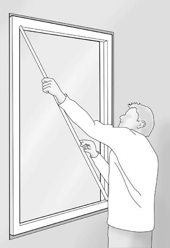
• Rod to measure diagonal
Selection of mounting material depends on type of wall.
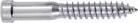
Lightweight concrete 8x120 mm with plug
Concrete and brick 8x80 mm with plug
Wood 8x64 mm
Steel 5.4x32 mm
Frame sleeve:
28 mm for caulking gap up to 10 mm
38 mm for caulking gap up to 15 mm
Pressure distribution washer for frame sleeve
Levelling block 10 – 17 mm
Material for secondary moisture protection. E.g. butyl tape, tar paper or equivalent.
2.3.1 Hole dimensions
Hole dimensions in wall should be adapted so that there is a 10 - 15 mm space for caulking between frame and wall. This is sufficient for fixing, caulking and sealing the window or door in wall.
What is meant by hole dimensions, frame outer dimensions and space for caulking is illustrated below.
Hole dimensions in the wall Frame outer dimensions
Extra space for caulking
Hole dimensions in the wall Frame outer dimensions
2.3.2 Module dimensions
Sizes of windows and doors are often given in modules. A module is an indication of hole dimensions in the wall in relation to frame outer dimensions and caulking space. 1 module (M) = 100 mm.
A window is 20 mm smaller than the module size, hole dimensions in the wall are executed in whole dm according to module dimensions. Example below:
Window and hole dimensions in wall (width/height) for module size M 9/13:
• Hole dimensions in wall, 900 mm x 1300 mm
• The window's frame outer dimensions, 880 mm x 1280 mm
• Caulking space 10 mm around the frame
To consider prior to installation:
• The structure into which the product is mounted must be able to manage the loads to which it is subject in the form of the window's own weight, wind load against the window and payloads.
• Positioning of frame sleeves differs between products both vertically and laterally, contact us for more information.
• Secondary moisture protection should be installed in the bottom of the wall's hole.
• Space for sufficient incline of window sill should be created in wall, 25° is recommended, but a minimum of 14°.
• Drip plate should be installed above window opening according to AMA Hus.
• It must be possible to readjust the product.
• The function of a Top Swing window for plastering mode requires that the outer sash is not lower than 20 mm on the sash upper piece, otherwise the sash strikes the jamb lining when turning so that the latch is not activated.
Located in the bottom of the wall's hole, raise 100 mm on the wall sides. The secondary moisture protection must ensure that any moisture can be drained out from the wall. For positioning, see outline diagram on page 4.
Place blocks of durable material in the bottom of the wall's window opening max. 100 mm from side. The blocks should create a space between frame and wall of 10 – 15 mm. If possible, blocks should have 20 mm less depth than the frame to facilitate unbroken caulking. The blocks are levelled with a spirit level so that the window is installed horizontally.
• Wide, fixed frames with glass dimensions of over 1200 mm must be wedged according to point 3.2.1.
• Doors must also be wedged underneath the middle of the threshold, see point 3.2.2.
• Windows with frame posts are wedged according to point 3.2.3.
3.2.1 Wedging wide, fixed frames
If the width of the glass area exceeds 1200 mm, wedging must not be performed under frame sides, but rather placed in the glass's quarter points, these are marked on the glass.
3.2.2 Wedging doors
Doors must be wedged according to 3.2, as well underneath the middle of the threshold so that the threshold does not sag under a load.
Marking Marking
Wedging shall take place at markings
<100 mm
<100 mm
3.2.3 Positioning of blocks at frame post
If the window is a combination window (openable and fixed parts within the same frame), or has two or more casements (glass), blocks are installed under all vertical sides and posts. If the width of the glass area in the fixed frame exceeds 1200 mm, additional blocks must be inserted at the quarter points of the glass according to 3.2.1.
To facilitate installation and adjustment, sashes and door leafs on certain products can be lifted from the frame. The sashes in a top swing window must not be lifted out from the frame in connection with installation, instead, the entire window is to be lifted into the wall opening, see section 3.5. Before frames are lifted into the wall opening, support blocks are to be placed on the outside that prevent the product from falling out from the wall opening according to point 3.3.3. Ensure that frame sleeves and any pressure distribution washers are installed before the frame is lifted into the wall opening.
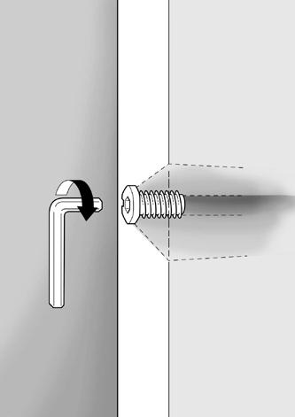
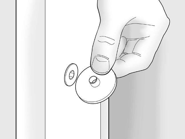
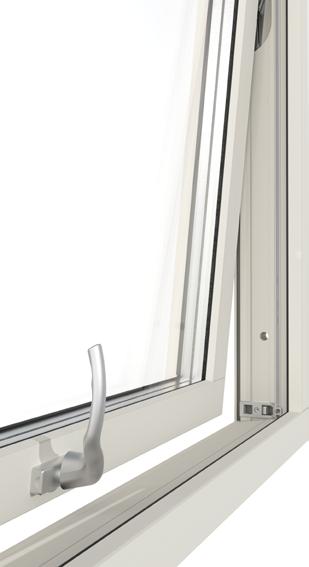
Screw frame sleeves in from the outside in all pre-drilled holes using an Allen key or installation tool, unless frame sleeves are already pre-installed. It is recommended that a pressure distribution washer is used for a more stable installation. When installing side-hung products of over 80 kg in weight, a pressure distribution washer should always be used to counteract sagging.
Note that 38 mm frame sleeve must be used if the caulking gap exceeds 10 mm.
3.3.2 Lifting sashes and door leafs out from frames
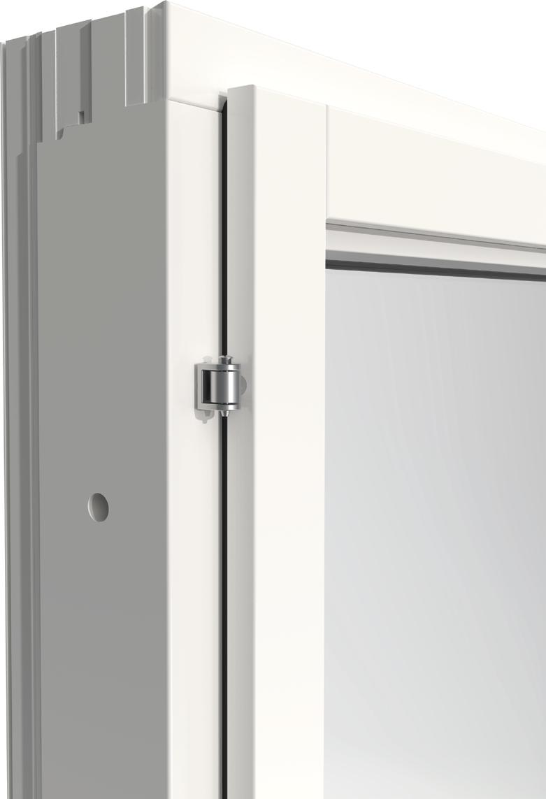
3.3.2.1 Products with lift-off hinges
Open outward-opening side- or top-hung window products and release any brake. Insert a screwdriver between the brake's arm and the brake fitting and turn so that the pin releases. Protect the wooden frame so that it is not damaged. Lift from sash and place on a plank or board leaned against a stable wall. Take care that the aluminium cladding does not touch the underlying surface.
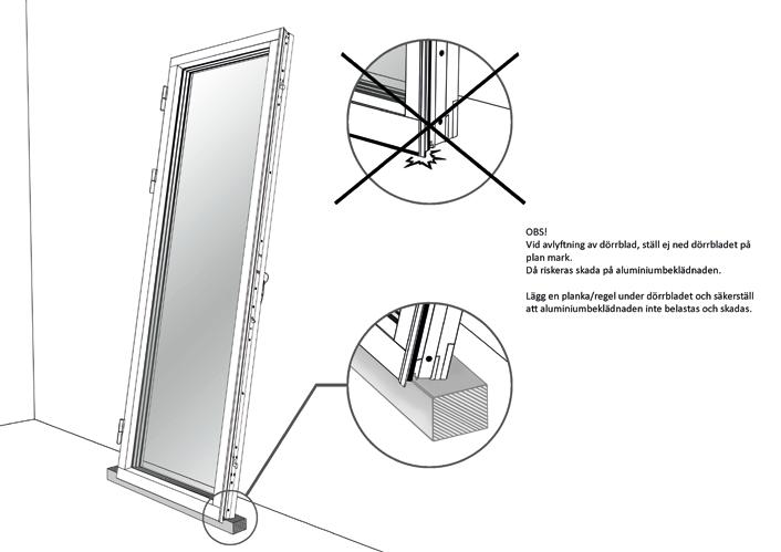
Note. When lifting off door leafs, do not place the door leaf on a flat surface. There is then a risk of damaging the aluminium cladding.
3.3.2.2 Inward-opening products with bolt hinges
On inward-opening side-hung or bottom hung windows, first release brake or scissor fitting. Then pins in bolt hinges are removed and sash is placed on a soft surface leaning against a wall.
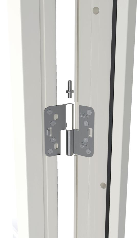
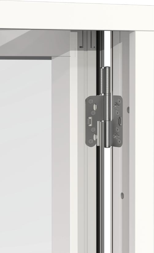
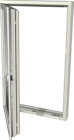
3.3.2.3 Side-hung sashes with Kipp-Dreh function
The sashes are lifted out of the frame as illustrated below, note that sash must be in side-hung position with handle straight upward.
Press the lock pin downward in the top hinge. Allow the lock pin to remain in place at the bottom of the frame mount. Note that the sash's top part is loose after this operation.
Release the sash's hinge from the frame mount by leaning the sash's top edge against you.
Then lift the sash upwards to release the lower hinge from the frame mount.
3.3.2.4 Side-hung sashes with concealed Kipp-Dreh function
The sashes are lifted out of the frame as shown below.
Turn the handle straight up (a) and open the sash in side-hung position (b).
Press in the malfunction catch (a) and turn the handle back to horizontal position (b).
Turn the lock plate (a) 90°, then release the frame's scissor arm from the top edge of the sash (b).
Open the sash approx. 15° (a) and lift it in order to release the sash from the frame mount (b).
3.3.3
Ensure that the window product cannot fall out through the wall opening when installing, for example, by placing support on the outside of the wall opening. Then lift the window product into the wall opening on the blocks that have been put in place. For top-swing window, also place a safety block on the inside of the bottom frame rail after the window has been lifted into the wall opening.
When the frame has been lifted into the wall opening, it has to be adjusted and fixed in the wall. The method can vary depending on type of window, to install top-swing window, see section 3.5. Check that caulking gap is equal all the way round and unscrew the frame sides' top and bottom frame sleeves so that they touch the wall side. Check the frame's position with a spirit level and rod for measuring diagonal.
3.4.1 Fixing
Fix the frame in the wall with screws through the unscrewed frame sleeves. Use screws that are adapted according to wall type, see section 2.2.2. Check diagonal measurement and caulking gap. Unscrew the remaining frame sleeves so that they touch the wall, secure with screws. Check that the frame is not bulging in any direction according to description above.
3.4.2
Adjust the frame if necessary by slightly loosening the screws, adjust frame sleeve with key, and then tighten the screws. Rehang the sash in frame according to section 3.4.3.
3.4.3 Installing sash in frame
When frame has been installed in wall opening and dimensions checked, the sashes that have been lifted out of the frame shall be reinstalled according to the below points. Check that they run freely and lock when closed, and also inspect all other functions. If necessary, certain fittings can be adjusted, this is described in section 4.
3.4.3.1 Outward-opening side- or tophung window products
Rehang sash on hinge, if the product has a brake, press its arm into the frame mount before the product is closed.
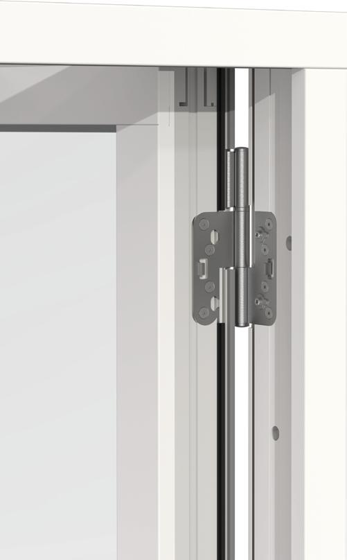
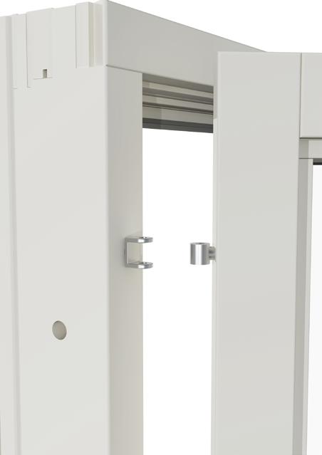
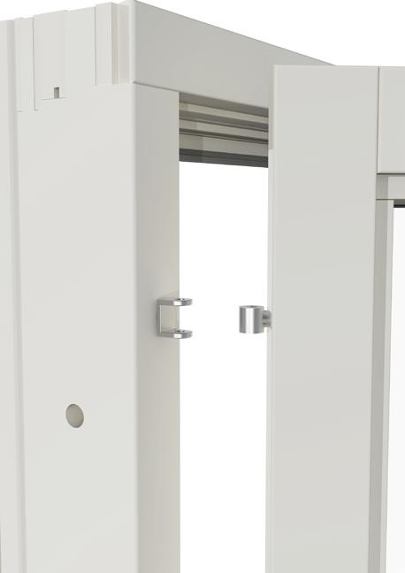
3.4.3.3 Side-hung sashes with Kipp-Dreh function

The sash's upper hinge is pressed into the frame mount. Note that bushings on the sash's hinge must be parallel with the frame's mount.
The lock pin in the upper hinge is pressed back from below.
3.4.3.4 Side-hung sashes with concealed Kipp-Dreh function
1 2 3 4 5 6 7
Turn out the lower frame mount approx. 15°
Ensure that the handle is in horizontal position.
The sash's lower hinge is inserted in the frame mount. The pin (a) on the frame mount shall be guided into the sash's hinge sleeve at the same time as the pin (b) is guided into the groove in the fitting rail in the sash's lower edge.
Connect the frame's scissor arm with the sash's top side. Guide the pin (a) into the scissor arm's hole at the same time as the pin (b) is guided into the groove in the fitting rail in the sash's top edge, and then turn back the lock plate (c).
Press in the malfunction catch (a) and turn the handle straight up (b).
Close the sash.
Turn the handle down
The sash in a top-swing window must not be lifted out from the frame during installation, instead the entire window is to be lifted into the wall opening. Install frame sleeves and any pressure distribution washers according to 3.3.1 and position safety blocks that prevent the window from falling out according to 3.3.3.
Use a spirit level to check that the frame is straight in all sides and not leaning inwards or outwards according to point 3.4. Adjust if necessary. Secure the frame in the wall with screws through the unscrewed frame sleeves, use screws than are adapted to wall type, see section 2.2.2.
Lift the window into the wall opening on the blocks that have been positioned according to point 3.2. Open the sash until the frame sides' lower frame sleeves can be reached, unscrew them so that they are touching against the wall side with a 10-15 mm caulking gap. 1 2 3
Open sash so that upper frame sleeves can be reached. Use a spirit level to check that the frame is straight, that it is not leaning inwards or outwards according to point 3.4. Fix screws in the frame sides' upper frame sleeves. Where the window has more fixing points, these must be used. Check diagonal measurement and test all the window's functions by turning the sash around, as well as testing catch and lock functions. The sash's top fitting must run freely in the frame sides' slide rails. Adjust the frame sleeves if necessary.

Below is a description of adjustment options for various problems in connection with installation.
Bear in mind that a discrepancy of mm at one end can be cm at the other. Ensure to measure, level and align frame and threshold. The product may also need to be readjusted when it has been installed for a while.
The upper part of the window/door sash catches in top edge. Adjust the frame according to the arrows using the frame sleeves.
The upper part of the window/door sash catches in top edge. Adjust according to the arrows using the hinges according to section 4.
The front part of the window/door sash catches in bottom edge. Use the frame sleeves to adjust the frame according to the arrows.
The lower part of the window/door sash catches in bottom edge. Adjust according to the arrows using the hinges according to section 4.
Readjustments, which can be executed on certain fittings as described in this section, can be required to ensure that the installed product runs freely and shuts correctly. Adjustment of the frame via frame sleeves is described in section 3.
4.1 Adjustment options in hinges
Certain hinges are only adjustable vertically, others laterally as well. Hinges for Retro and MF Duo are not adjustable.
4.1.1 Outward-opening side-hung products, vertical adjustment
Unscrew the hinge's cover (1), protect the varnish when using tools.
Adjust the sash's height with an Allen key (2), size 5, remember to adjust all hinges equally.
4.1.2 Outward-opening linked French doors, vertical adjustment
The outer sash must be removed before adjustment. Divide inner- and outer sash by opening closing fitting (1), the outer sash can then be removed and adjustment executed as illustrated. Remember to adjust all hinges equally.
1 Open closing fitting
2 Undo screw pin on upper and lower hinge, as well as cover on the middle one
3 Screw with an Allen key, size 5, for vertical adjustment
4.1.3 Outward-opening linked French doors, lateral adjustment
The sash's lateral position can be adjusted via the hinge part on the frame, adjust as illustrated below. Note that fixing screws must not be completely unscrewed, they must remain hanging.
Lateral adjustment, in
1. Screw adjustment screws counter-clockwise
2. Tighten fixing screws
Lateral adjustment, out
1. Slightly loosen fixing screws
2. Screw adjustment screws clockwise
3. Tighten fixing screws again
Bolt hinge for inward-opening window products can be adjusted depth-wise and laterally. Hang from the sash according to 3.3.2.2.
Screw the hinge in or out of the sash for adjustment of the sash's lateral positioning as in picture A.
Screw the hinge in or out of the frame for the sash's depth positioning as in picture B. One turn produces approx. 1 mm of adjustment of the sash's position in relation to the frame.
Note that products with more than two hinges can also require adjustment of centre hinge.


The sash's closing pressure against the frame can be increased or decreased by adjusting the espagnolette's latches. A size 11 wrench can be used to adjust latches.
Adjustments of fittings for Kipp-Dreh should only be carried out by a specialist window company. The sash's vertical and lateral position can be adjusted via the fitting's upper and lower hinges.
Justering sidled
Closing pressure
In addition to options for adjustment of closing pressure according to point 4.3, it can be adjusted in the hinge on Kipp-Dreh hung windows according to the below.
Stängningstryck
4.5 Sash's position concealed Kipp-Dreh window
Table of contents
Sidojustering
Stängningstryck
Stängningstryck
Insert a screwdriver or similar into the loop and turn it to the desired position.
Repeat if further adjustment is required. When the fitting is turned clockwise the closing pressure increases. when it is turned counterclockwise, the closing pressure decreases.
Note that the fitting can be damaged if the closing pressure is set too tight, but if it is set too loose, air and water leakage can occur between the sash and frame. Also note that the fitting can be damaged if you turn the fitting in the handling loop without the help of a screwdriver.
The window should be placed in warm part of the wall. To achieve satisfactory air seal and insulation, as well as protect from damp penetrating in, the installation should be executed as follows.
• Caulking (1) should be executed with mineral wool to insulate between window and wall. If foam sealant is used, it must be flexible to ensure the window's function and also so that the frame can be readjusted. Leave space for retention strip (2) and elastic sealant (3) on inside as well as approx. 10 mm air gap (4) in relation to the window's outside.
• Place retention strip (2) and an elastic joint, alternatively, diffusion-tight tape (3) on inside to seal against the wall's vapour barrier (5).
• If the product is installed out in the wall's air gap, a drip plate should be installed at the top to convey out any damp. Design and fit the strip according to AMA Hus section JTB.522.
• Design and fit window sill (6) according to point 5.1.1. For installation of tinplate in threshold see point 5.1.2, installation of tinplate in low threshold, see section 5.1.3.
• Exterior weather protection (7) must connect to the window to prevent moisture forming from torrential rain. To secure side plates, see point 5.1.4.
1. Caulking/insulation
2. Retention strip
3. Jointing compound,alt.diffusion-tight tape
4. Air gap
5. Vapour barrier
6. Window sill
7. Exterior weather protection
Section Lower Section side
Unless indicated otherwise, the instructions in AMA Hus should be followed.
5.1.1 Window sill and tinplate for inward-opening French doors
Window sill should be designed and installed according to AMA Hus section JTB.521 and should have an incline of 25°, min. 14°. Jointing compound should be laid in the groove regardless of whether plates are installed in groove or not, and also between window sill and bottom frame rail. Screws are to be used for fixing.
Skruv
Tätning
Screw
Fönsterbleck
Windowsill
Jointed compound
Outward-opening product
Screw
Skruv
Fönsterbleck
Windowsill
Tätning
Jointed compound
Inward-opening product
5.1.2 Tinplate in standard threshold for outward-opening French doors
Tinplate for thresholds should be designed according to AMA Hus section JTB.524. The tinplate is secured with screws in the threshold's aluminium part and sealed with jointing compound.
Skruv
Screw
Fönsterbleck
Windowsill
Jointed compound along the entire width of the threshold
Mjukfog längs hela tröskelns bredd
5.1.3 Installing tinplate in low threshold for outward-opening French doors
Tinplate for thresholds should be designed according to AMA Hus section JTB.524. Tinplate is secured with a rubber trim that is threaded onto the plate and pressed into the threshold's groove. Alternatively, jointing compound is laid in the groove and the plate is secured with rivets from above through the threshold. Another fixing may potentially be required depending on positioning and other circumstances.
point Jointed compound
Sill plate Rubber strip Sill plate
5.1.4 Installing side plates in jamb
Side plates should be fixed in aluminium cladding with jointing compound in the cladding's groove, fixing shall also take place in wall with a suitable fixing adapted for the wall structure, e.g. clamp, screw or nail. The fixing point in the wall must be load-bearing.
If securing in groove is not possible, the plate can be fixed in the aluminium cladding with pop rivets in aluminium.
Window products must be installed in a frame that is designed to take loads from the window's own weight, wind load against the window, payloads, and also that the product's functions are ensured. The installation must also be executed to enable readjustment.
If several window products are installed together, the contractor must verify this installation in construction calculations for the unique building.
Installation of frame against frame is described below.
It is possible to mount windows frame against frame. The frame sleeves on the sides are offset vertically and can be used for fixing.
Use screws adapted for wood. Take care not to use screws that are too long. Seal with jointing compound between windows to ensure an air tight installation.
The space between the frames must be sealed on the outside, e.g. with a connecting plate. The connecting plate should be secured in the cladding with jointing compound in the cladding's groove. Products that do not have a groove for connecting plate, must instead be riveted with a pop rivet in aluminium.
When installing frame against frame, the hinge side of side-hung window products must always be installed in the wall part.
Anslutningsplåt
Connection plate with jointing compound
Jointing compound
6.1.2 Frame against frame vertically
It is possible to mount windows frame against frame. Use any frame sleeves supplied and secure with screws adapted for wood. To stabilise the installation, it is recommended that nail plate is screwed onto the frame sides. This also simplifies sealing at the z-profile's ends. Take care not to use screws that are too long. Seal with jointing compound between the frames as well as between nail plate and z-profile to ensure an air- and water tight installation.
Jointing compound
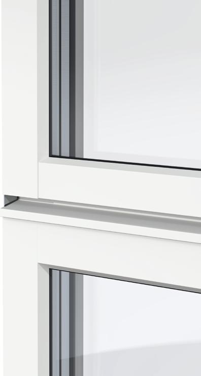
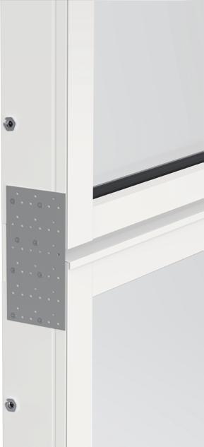
When installing windows frame against frame vertically, it is important that water can run off in order to protect the lower product. This can be achieved with a Z-profile secured with screws and sealed with jointing compound against frame.
Fogmassa
Jointed compound
Cover strip Screw Z-profile
Jointed compound
Täcklist Skruv Z-Profil Silikon
The ventilation hatch can be mounted frame to frame with another window product. It is possible to use frame sleeves on the side of the adjacent product for fixing to the ventilation hatch. Use screws adapted for wood. Be careful not to use screws that are too long. Seal with jointing compound between the window and the ventilation hatch to ensure an airtight installation.
The gap between the frames should be sealed on the outside, for example, with a connection plate. The connection plate should be secured to the cladding with jointing compound in the cladding’s groove.
For products that lack a groove for the connection plate, it should instead be riveted with a pop rivet in the aluminum cladding. When mounting frame to frame, the hinge side of side-hung window products must always be installed in the wall section. The ventilation hatch has frame sleeves at the top and bottom that are used for fixing to the wall.
Connection plate with jointing compound
compound
7
6.2.1 Installation of fire windows approved for CE-marking and type approval in fire rating up to E 30, EW 30 and EI 30.
CE-marked products with classified fire resistance covered by certificate 0402-CPR-SC1237-17 or 0402-CPR-SC1238-17 shall be Installed according to the below instructions. The instructions also apply for fixed fire-rated windows that are covered by type approval SC0354-19, SC0471-10 as well as 0108/05.
The product's fire rating is only valid if the product is installed according to one of the methods below. Fire installation can be executed with or without a retention strip, it is also permitted to install a fire window in another window with a wooden frame. The diagram below illustrates approved installation method, the table describes approved material, dimensions and brands.
Note that no requirements are placed on material or design of exterior rain seal or interior jamb reveal with respect to fire resistance.
2 1
6 5 4 3
1 Fixing Installation in concrete or lightweight concrete Min. 100 mm
Installation in steel studs
Installation in wooden joists
Min. 95 mm steel stud
Min. 95 mm wooden joist
Installation in other window/door in wood Min. 95 mm wooden frame
2 Window frame Distance between side of frame and wall/ window/door shall be 10 – 15 mm. Can be installed in other window with no gap between the windows.
3 Frame sleeve Fixing consists of frame sleeve and screw for frame installation
4 Screw for frame installation Fixing in concrete wall with plastic plug
mm Adjufix Fixing in steel stud
mm Adjufix Fixing in wooden joist 8x50 mm
Bufab
8x64 mm Bufab 8x64 mm thick Bufab
5 Caulking Caulking material Roxremsa
Caulking material Isover Ultimate Drev
Caulking material Paroc FPY Fireproof 30 CR/100
mm Rockwool
mm Isover
mm Paroc Caulking material Sika
6 Retention strip Retention strip for inner seal
7 Inner seal Sealant for air- and diffusion seal Sika 225 Connection 105 ml/m Sika
Sika Hyflex-402 Sika
Sikasil 670 Fire Sika
Soudalseal 211 Interior Soudal
Soudalseal 222 LM 105 ml/m Soudal
Soudalseal 225 LM 105 ml/m Soudal
4
5
6.2.2 Installation of fire windows type approved in fire rating E 60, EW 60 and also EI 60
Installation of type approved fixed window with classified fire resistance in class E 60, EW 60 EI 60 covered by certificate C900267 shall be installed as described below.
The product's fire rating is only valid if the product is installed according to one of the methods below. The table describes approved material, dimensions and brands. Installation in another window with a wooden frame can be executed with no gap between the windows.
Note that no requirements are placed on material or design of exterior rain seal or interior jamb reveal with respect to fire resistance.
2 1
3
1 Fixing Installation in concrete or lightweight concrete Min. 150 mm
Installation in wooden joists Min. 125 mm
2 Window frame Distance between side of frame and wall/window/ door shall be 10 – 15 mm.
Installation in another window with a wooden frame can be executed with no gap between the windows. 10 mm -15 mm
3 Frame sleeve Fixing consists of frame sleeve and screw for frame installation
4 Screw for frame installation Fixing in concrete wall with plastic plug
Fixing in wooden joist
5 Caulking Caulking material Roxremsa
mm Rockwool Caulking material Isovver Ultimate Drev
mm Isover
Installation of burglary-rated products requires the frame to be butt jointed at all locking points such as lock plate and hinge, this can also be performed when installing products that are not burglary-rated where reinforced burglary protection is required. This entails placing blocks made of hard material at lock points in the caulking gap to prevent the frame from turning under impact. An installation with reinforced burglary protection should be executed with pressure distribution washer mounted on frame sleeve.
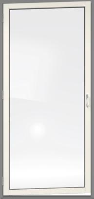
6.4 Installation of facad windows
Facade windows are always installed on the whole wall and not in a wall opening like ordinary windows.
• Fixing to a wall
The frame is fixed to the wall with screws adapted to the type of wall, see section 2.2.2.
• Installation of frame aluminum
After the frame is mounted on the wall, the aluminum profiles of the frame are snapped onto the plastic clips of the frame.
The aluminum is mounted in the following order:
1. lower part
2. sides
3. upper part
4. horizontal item (if available)
5. Standing item (if available)
If the product is not to be reused, remove the glass, fittings, rubber trims etc. and take to recycling or energy recovery. Contact local waste processors for more information. For an account of the window’s material content, refer to the product's Building Product Declaration, which is available at www.byggmaterialindustrierna.se. Depending on type of product, the procedures vary to prepare the product's different materials for recycling. The respective fractions are sorted according to the local waste processors.