
IL RANKER SERIES FOR MODULE-5 GRADE 12
by
ILRankerSeriesPhysicsforNEETGrade12Module5
ISBN978-81-971195-0-7[FIRSTEDITION]
Thisbookisintendedforeducationalpurposesonly.Theinformationcontainedhereinisprovidedonan“as-is”and “as-available”basiswithoutanyrepresentationsorwarranties,expressorimplied.Theauthors(includinganyaffiliated organizations)andpublishersmakenorepresentationsorwarrantiesinrelationtotheaccuracy,completeness,or suitabilityoftheinformationcontainedinthisbookforanypurpose.
Theauthors(includinganyaffiliatedorganizations)andpublishersofthebookhavemadereasonableeffortsto ensuretheaccuracyandcompletenessofthecontentandinformationcontainedinthisbook.However,theauthors (includinganyaffiliatedorganizations)andpublishersmakenowarrantiesorrepresentationsregardingtheaccuracy, completeness,orsuitabilityforanypurposeoftheinformationcontainedinthisbook,includingwithoutlimitation, anyimpliedwarrantiesofmerchantabilityandfitnessforaparticularpurpose,andnon-infringement.Theauthors (includinganyaffiliatedorganizations)andpublishersdisclaimanyliabilityorresponsibilityforanyerrors,omissions, orinaccuraciesinthecontentorinformationprovidedinthisbook.
Thisbookdoesnotconstitutelegal,professional,oracademicadvice,andreadersareencouragedtoseekappropriate professionalandacademicadvicebeforemakinganydecisionsbasedontheinformationcontainedinthisbook.The authors(includinganyaffiliatedorganizations)andpublishersdisclaimanyliabilityorresponsibilityforanydecisions madebasedontheinformationprovidedinthisbook.
Theauthors(includinganyaffiliatedorganizations)andpublishersdisclaimanyandallliability,loss,orriskincurred asaconsequence,directlyorindirectly,oftheuseand/orapplicationofanyofthecontentsorinformationcontainedin thisbook.Theinclusionofanyreferencesorlinkstoexternalsourcesdoesnotimplyendorsementorvalidationbythe authors(includinganyaffiliatedorganizations)andpublishersofthesame.
Alltrademarks,servicemarks,tradenames,andproductnamesmentionedinthisbookarethepropertyoftheir respectiveownersandareusedforidentificationpurposesonly.
Nopartofthispublicationmaybereproduced,stored,ortransmittedinanyformorbyanymeans,includingwithout limitation,electronic,mechanical,photocopying,recording,orotherwise,withoutthepriorwrittenpermissionofthe authors(includinganyaffiliatedorganizations)andpublishers.
Theauthors(includinganyaffiliatedorganizations)andpublishersshallmakecommerciallyreasonableeffortsto rectifyanyerrorsoromissionsinthefutureeditionsofthebookthatmaybebroughttotheirnoticefromtimetotime.
AlldisputessubjecttoHyderabadjurisdictiononly.
Copyright © 2024 Rankguru Technology Solutions Private Limited. Allrightsreserved.
A Tribute to Our Beloved Founder
Dr. B. S. Rao

Dr.B.S.Rao,thevisionarybehindSriChaitanyaEducationalInstitutions,iswidelyrecognisedfor hissignificantcontributionstoeducation.Hisfocusonprovidinghigh-qualityeducation,especially inpreparingstudentsforJEEandNEETentranceexams,haspositivelyimpactednumerouslives. ThecreationoftheILRankerSeriesisinspiredbyDr.Rao’svision.Itaimstoassistaspirantsin realisingtheirambitions.
Dr.Rao’sinfluencetranscendsphysicalinstitutions;hiseffortshavesparkedintellectual curiosity,highlightingthateducationisajourneyofempowermentandpursuitofexcellence. Hisadoptionofmodernteachingtechniquesandtechnologyhasempoweredstudents,breaking throughtraditionaleducationalconstraints.
AswepayhomagetoDr.B.S.Rao’senduringlegacy,weacknowledgetheprivilegeof contributingtothecontinuationofhisvision.Hisremarkablejourneyservesasapoignant reminderoftheprofoundimpacteducationcanhaveonindividualsandsocieties.
With gratitude and inspiration
Team Infinity Learn by Sri Chaitanya
Key Features of the Book
Chapter Outline
1.1 Electric Charges
1.2 Coulomb’s Law
1.3 Forces between Multiple Charges
This outlines topics or learning outcomes students can gain from studying the chapter. It sets a framework for study and a roadmap for learning.
This section highlights the essential takeaways from the discussion while also serving as a mnemonic device to help students recall key concepts.
Application
Abodydroppedfreelyfromamultistory buildingcanreachthegroundin t1seconds. Itisstoppedinitspathafter t2secondsand againdroppedfreelyfromthepoint.Findthe furthertimetakenbyittoreachtheground.
Key Insights:
■Rangeofgravitationalforce>rangeof electromagneticforce>rangeofnuclear force
■Strengthofnuclearforce>strength ofelectro-magneticforce>strength
This illustrates the application of the discussed concepts to a physical model.
Solved Examples
Specific problems are presented along with their solutions, explaining the application of principles covered in the textbook.
Q.Twolargenon-conductingsheets A and B, havingchargedensities+2σ C/m2and– σ C/m 2arekeptparalleltoeachother.Find electricfieldatpoint P
Sol. EQ A Q A Q pA 2 22 3 0020
Try yourself:
Howmuchpositiveandnegativechargeisthere inacupofwater?Assumethatmassofonecup ofwateris250g.
Ans: ×101.34C7
Try Yourself enables the student to practice the concept learned immediately.
This comprehensive set of questions enables students to assess their learning. It helps them to identify areas for improvement and consolidate their mastery of the topic through active recall and practical application.
TEST YOURSELF
1.Ifachargeonthebodyis–1nC,then howmanyexcesselectronsarepresent onthebody?
(1)1.6 × 10¹⁹(2)6.25 × 10⁹
(3)6.25 × 1027(4)6.25 × 1028
CHAPTER REVIEW
Electric Charges and Field
■Electricchargeisalwaysassociated withmass.
■Electricchargeisrelativistically invariant.
It offers a concise overview of the chapter’s key points, acting as a quick revision tool before tests.
This is a focused practice with topic-wise questions based on NCERT textbook content. It is designed to enhance students’ success in NEET by aligning with recent exam trends.
Exercises
NEET DRILL THEORY-BASED QUESTIONS
Single Option Correct MCQs
Statement Type Questions
Assertion and Reason Questions
BRAIN TEASERS
Modelled after the NEET exam format, this test is based on a specific chapter. It serves as a tool for students to evaluate their time management skills and gauge their mastery level in a particular chapter.
FLASHBACK
These questions deepen the understanding of concepts and strengthen the interpretation of theoretical learning.
These complex questions that combine fun and critical thinking are aimed at fostering higher order thinking skills and encourage analytical reasoning.
CHAPTER TEST
Hand-picked questions from previous years NEET offer an insight into the types of questions and the important topics that are probable to appear in NEET.
RAY OPTICS AND OPTICAL INSTRUMENTS
Chapter Outline
9.1 Reflection of Light
9.2 Refraction of Light at Plane Surface
9.3 Refraction of Light at Spherical Surfaces and by Lenses
9.4 Prism
9.5 Some Natural Phenomena
9.6 Optical Instruments
9.7 Aberrations
Nature has endowed the human eye (retina) with the sensitivity to detect electromagnetic waves within a small range of the electromagnetic spectrum.
Electromagnetic radiation (wavelength from 400 nm to 750 nm) is called light. It is mainly through light and the sense of vision.
Light travels along a straight line with enormous speed. The speed of light in vacuum is the highest speed attainable in nature. The speed of light in vacuum is 8181 2.9979245810ms310ms. c =×≈×
The wavelength of light is very small compared to the size of ordinary objects that we encounter commonly (generally of the order of a few cm or larger). A light wave can be considered to travel from one point to another, along a straight line joining them. The path is called a ray of light, and a bundle of such rays constitutes a beam of light.
In this chapter, the phenomena of reflection, refraction, and dispersion of light are considered using the ray picture of light. We shall study the image formation by plane and spherical reflecting and refracting surfaces, using the basic laws of reflection and refraction. The construction and working of some important optical instruments, including the human eye, are also explained.
9.1 REFLECTION OF LIGHT
When a light ray strikes the boundary of two media, such as air and glass, a part of light is turned back into the same medium. This is called reflection of light.
In case of reflection at the point of incidence O , the angle between the incident ray and the normal to the reflecting surface is called the angle of incidence ( i). The angle between the reflected ray and normal to the reflecting surface is called angle of reflection ( r). The plane containing incident ray and normal is called the plane of incidence.
Laws of reflection
i) The incident ray, the reflected ray and the normal to the reflecting surface at the point of incidence, all lie in the same plane.
ii) The angle of incidence is equal to the angle of reflection.
Types of reflection
Regular reflection: When the reflection takes place from a perfect smooth plane surface, then the reflection is called regular reflection or specular reflection.
In this case, a parallel beam of light incident will remain parallel even after reflection, as shown in the figure.
Diffused reflection: If the reflecting surface is rough (or uneven), parallel beam of light is reflected in random directions. This kind of reflection is called diffused reflection. If the average height of roughness is less than the wavelength of incident light, then diffused reflection takes place.
iii) In case of reflection of light, frequency, wavelength and speed do not change, but the intensity of light will decrease on reflection.
iv) If the reflection of light takes place from a denser medium, there is a phase change of π rad.
v) Deviation of a ray due to reflection: The angle between the direction of incident ray and reflected light ray is called the angle of deviation ( δ ).
From the figure, δ = π – (i+r)
But i = r
Hence, angle of deviation in the case of reflection is δ = π – 2i
We see non-luminous objects by diffused reflection.
Important points regarding reflection
i) Laws of reflection are valid for all reflecting surfaces, either plane or curved. For spherical surfaces, the normal is to be taken as normal to the tangent to surface at the point of incidence, i.e., the normal is along the radius, which is the line joining the centre of curvature of the mirror to the point of incidence.
vi) By keeping the incident ray fixed, the mirror is rotated by an angle θ , about an axis in the plane of the mirror, and the reflected ray is rotated through an angle of 2 θ
ii) If a light ray is incident normally on a reflecting surface, after reflection, it retraces its path, i.e., if 0, i ∠= then 0. r ∠=
vii) Vector form of law of reflection: If 1 ˆ e is unit vector along the incident ray, 2 ˆ e is the unit vector along the reflected ray and ˆ n is the unit vector along the normal, then
9.1.1 Reflection from Plane Surfaces
In a plane surface, when light gets reflected following scenarios are observed.
Nature of Image
Real and virtual object: If a surface is incident with a divergent beam, it means that a real object is placed in front of the surface at the position from where the rays are diverging, as shown in figure (a).
• (a)
If a surface is incident with a converging beam, it means that a virtual object is placed behind the surface at the position where the rays appear to converge, as shown in the figure (b). In case of image formation, unless stated the object is taken to be real. It may be a point object denoted by a dot ( • ) or an extended object denoted by an arrow ( ↑ ).
Real and virtual image: The optical image is a point where the rays of light either intersect or appear to intersect. If the real rays after reflection or refraction actually converge at a point, the image is said to be real, as shown in figure (a). However, if the rays do not actually converge but appear to do so, the image is said to be virtual. This is shown in the figure (b).

The eye sees a virtual image as well as a real image. A real image contains light energy.
Hence, it can be seen on a screen and photographed. On the other hand, a virtual image cannot be received on a screen.
1) When you look into a plane mirror, you see an image of yourself that has three properties:
(i) The image is upright.
(ii) The image is the same size as you are.
(iii) The image is located as far behind the mirror as you are in front of it. This is shown in the figure (b).
2) A plane mirror always forms a virtual image of a real object and vice versa, and the line joining the object and the image is perpendicular to the plane mirror, as shown in figure (a).
The graph between image distance (v) and object distance (u) for a plane mirror is a straight line as shown in figure ( b).
The ratio of image height to the object height is called lateral magnification (m). Thus, in case of plane mirror, ‘m’ is equal to one.
3) The principle of reversibility states that rays retrace their path when their direction is reversed. In accordance with the principle of reversibility, object and image positions are interchangeable. The points corresponding to object and image are called conjugate points. This is illustrated in figure.
4) A mirror, whatever be the size, forms the complete image of the object lying in front of it. A large mirror gives a bright or image than a small one. The size of the reflector must be much larger than the wavelength of the incident light. Otherwise, the light will be scattered in all directions.
5) The angle between directions of incident ray and reflected or refracted ray is called deviation ( δ ). A plane mirror deviates the incident light through angle δ = 180 –2 i , where i is the angle of incidence. The deviation is maximum for normal incidence. Hence, δ max = 180°
incidentray reflectedray
It is noted that generally, anti-clockwise deviation is taken as positive and clockwise deviation is taken as negative.
6) Every object has its own field of view for the given mirror. The field of view is the region between the extreme reflected rays, and it depends on the location of the object in front of the mirror. If our eye lies in the field of view, only then we can see the image of the object, otherwise not. This is illustrated in figure.
7) Velocity of image in case of plane mirror:
Let, XO / M = X coordinate of object w.r.t. mirror
XI / M = X coordinate of image w.r.t. mirror
YO / M = Y coordinate of object w.r.t. mirror
YI / M = Y coordinate of image w.r.t. mirror
For plane mirror, XO / M = –XI / M
Differentiating both sides w.r.t. t, d dt (XO / M) = d dt (XI /M); // ()() IMIMxx VV =− [] OxMxVV
= – [] IxMxVV 2 IxMxOxVVV =−
; Similarly, YI/M = Yo/m
Differentiating both sides w.r.t. t, we get
// ()() IMyOMyVV =
For solving numerical problems involving calculation of velocity of image of object with respect to any observer,we first calculate the velocity of image with respect to mirror, using the following formulas.
/||/||// ()(),()(), IMOMIMOM VVVV⊥⊥ ==−
//||/()() IMIMIM VVV=+⊥
Then, the velocity of image with respect to required observer is calculated using basic equation for relative motion.
/ ABV = Velocity of A with respect B. = ABVV
Key Insights:
■ If an object moves towards (or away from) a plane mirror at speed v, the image will also approach (or recede) at the same speed v, and the relative velocity of image with respect to object will be 2 v , as shown in figure (a). If the mirror is moved towards (or away from) the stationary object with speed v, the image will also move towards (or away from) the object with a speed 2v, as shown in figure (b).
8)A person of height h can see his full image in a mirror of minimum length 2 lh =
A person standing at the centre of a room, looking towards a plane mirror hung on a wall, can see the whole height of the wall behind him if the length of the mirror is equal to one-third of the height of the wall.
Q. A point source of light B is placed at a distance L in front of the centre of a mirror of width d hung vertically on a wall. A man walks in front of the mirror along a line parallel to the mirror at a distance 2 L from it as shown. Find the greatest distance over which he can see the image of the light source in the mirror.
Q. Find the velocity of the image of a moving object in the situation shown in figure. (Given velocity w.r.t ground)
5m/s O 10m/s 30m/s m
Sol. We know, for the perpendicular component,
⇒−=+⊥ ()70 IGV ⊥ =−
The parallel component of velocity of image is same as that of object w.r.t. ground. It does not depend on the velocity of mirror.
So, (VIG)|| = 5 m/s
Try yourself:
A plane mirror is placed at origin parallel to y-axis, facing the positive x-axis. An object starts from (2 m, 0, 0) with a velocity of ˆˆ (22) ij + m/s. Find the relative velocity of image with respect to object.
Ans: ˆ 4i
Locate the position of image and by the help of shortcut method of locating field of view join the mirror through lines, and that region is the field of view then, by similar triangle concept the triangles IPQ and IMN are similar, 3 3 PQLPQd MNL =⇒=
Try yourself:
A plane mirror is fitted on the wall of a room of length 30 ft and height 14 ft. A man is standing on the floor in front of the mirror at a distance of 10 ft from the mirror. Find the minimum length of the mirror for which the man can see the full image of the wall behind him.
Ans: 3.5 ft
9) If two plane mirrors are inclined to each other at an angle θ, the number of images of a point object formed is determined as follows:
(i) If 360 θ is an even number (say m), the number of images formed is n = (m - 1), for all positions of object in between the mirrors.
(ii) If 360 θ is an odd integer (say m), the number of images formed, n = m, if the object is not on the bisector of the angle between the mirrors. n = (m - 1), if the object is on the bisector of mirrors.
(iii) If 360 θ is a fraction (say m), the number of images formed will be equal to its integral part, i.e., n = [m].
Example: If m = 4.3, the total number of images, n = [4.3] = 4

Position of the object
Number of images (n)
Even Anywhere m – 1
Odd Symmetric m – 1
Asymmetric m
Fraction Anywhere [m]
10) All the images lie on a circle whose radius is equal to the distance between the object ‘O’ and the point of intersection of mirrors C. If θ is less, more number of images are formed on the circle with large radius.
11) If the object is placed in between two parallel mirrors, θ=0° , the number of images formed is infinite, but of decreasing intensity, in accordance with I
12) If ‘θ’ is given n is unique, but if n is given θ is not unique, since same number of images can be formed for different θ
13)The number of images seen may be different from number of images formed, and this depends on the position of the observer relative to object and mirror.
14)Whenever reflection takes place, the component of incident ray parallel to reflecting surface remains unchanged, while component perpendicular to reflecting surface (i.e., along normal) reverses in direction.
Consider incident ray along unit vector 1 ˆ e given 1 ˆˆ ˆ .exiyj =−− Unit vector along reflected ray will be given by 2 ˆˆ ˆ e xiyj=−+ and 3 ˆˆ ˆ exiyj =+ . It finally gets reflected as ^ e3 ^ e1 ^ e2 ^ j ^ i
Q. A plane mirror lies on z-x plane. Find the vector 234, ijk +− expression for the light vector after reflection.
Sol. The component () 24ik of the incident vector remains unchanged and the component 3 j gets reversed, therefore the reflected vector is 234ijk
Try yourself:
A plane mirror lies in the xy-plane. A light vector () ˆˆ 2ijk +− is incident on it. Find the unit vector along the reflected ray.
9.1.2 Reflection from Curved Surface
A curved mirror is a smooth reflecting part (in any shape) of a symmetrical curved surface, such as spherical, cylindrical or ellipsoidal. In this chapter, we consider a piece of spherical surface only.
Sign Convention
To derive the relevant formula for reflection by spherical mirrors and refraction by spherical lenses, we must adopt a sign convection for measuring distances. In this book, we shall follow the Cartesian sign convention. According to this convention all distances are measured from the pole of the mirror or optical centre of lens.
i) The distances measured in the same direction as the incident light are taken as positive and those measured in the direction opposite to the direction of light are taken as negative.
ii) The heights measured upwards with respect to x-axis and normal to the principal axis ( x -axis) of the mirror/lens are taken as positive (Figure). The heights measured downwards are taken as negative.
If the reflection takes place from the inner surface, the mirror is called concave, and if it takes place from the outer surface, the mirror is convex, as shown in the figure. In case of a thin spherical mirror, the centre C of the sphere of which the mirror is a part is called the centre of curvature of the mirror. P is the centre of the mirror surface, called the pole. The line CP produced is the principal axis. AB is the aperture, meaning that it is the effective diameter of the light reflecting area of the mirror. The distance CP is the radius of curvature (R). The point F is the focus. The distance between PF is called focal length ( f) and it is related to R as f = R/2.
iii) Acute angles measured from the normal (principal axis) in the anti-clockwise sense are positive, while these in the clockwise sense are negative.
Paraxial Approximation
Rays which are close to the principal axis or make a small angle ( θ<10° ) with it, i.e., they are nearly parallel to the axis, are called paraxial rays. Accordingly, we set
cos1,sinθ≈θ≈θ and tan θ≈θ . This is known as paraxial approximation or first order theory or “Gaussian” optics. In spherical mirrors, we restrict ourselves to mirror with small aperture and paraxial rays.
9.1.3 F ocal Length of Spherical Mirrors
We assume that the light rays are paraxial and they make small angles with the principal axis.
A beam of parallel paraxial rays is reflected from a concave mirror so that all rays converge to a point F on the principal axis which is called principal focus of the mirror and it is the real focus.
A narrow beam of paraxial rays falling on a convex mirror is reflected to form a divergent beam, which appears to come from a point ‘F’ behind the mirror. Thus, a convex mirror has a virtual focus ‘F’.
The distance between focus (F) and pole (P) is called the focal length f. Concave mirror is known as a converging mirror. It is used in head lights, of cars search lights and telescopes. Convex mirror is called a diverging mirror. Convex mirror gives a wider field of view than a plane mirror and concave mirror, and it is used as rear view mirror in vehicles.
Relation between f and R
According to Cartesian sign convention, with real object, the focal length of concave mirror is negative, because the distance PF (P to F) is measured in the opposite direction of light. Similarly, far the same reason, focal length of convex mirror is positive.
The same sign convention is also applicable to virtual object by assuming the imaginary light rays from that object.
A ray AM parallel to the principal axis of a concave mirror is reflected through the principal focus F . If C is the centre of curvature, CM is the normal to the mirror at M. MCP ∠=θ and 2 MFP ∠=θ
Now, tan MD CD θ= and tan2 MD FD θ=
For small ‘ θ ’, tan θ≈θ and tan22θ≈θ , tan22tan ∴θ≈θ (or) 2. MDMD FDCD = 2 CD FD ∴= ,
Now, for small θ , the point D is very close to the point P. Therefore, FD = f and CD = R. 2 fR
∴=
The focal length of the mirror is independent of the medium in which it placed and wavelength of incident light. For a plane mirror, focal length f is infinite (as R =∞ ).
Rules for Image Formation
In general, the position of image and its nature [i.e., whether it is real or virtual, erect or inverted, magnified or diminished], to an object, depend on the distance of the object from the mirror. Nature of the image can be obtained by drawing a ray diagram. In case of image formation unless stated, the object is taken to be real, and it may be a point object or extended.
i) A ray parallel to the principal axis, after reflection from the mirror, passes or appears to pass through its focus F.
ii) A ray passing through or directed towards the focus, after reflection from the mirror, becomes parallel to the principal axis (by principle of reversibility).
iii) A ray through or directed towards the centre of curvature C, after reflection from the mirror, retraces its path.
iv) A ray striking at pole P is reflected symmetrically back in the opposite direction.
Fig. (a) Fig. (b)
∆ ABC and ∆ A'B'C are similar, and hence, ''' ABCB ABCB = ...... (1)
From figure (b), ∆ ABP and ∆ A'B'P are similar.
Hence, ''' ABPB ABPB = .......(2)
9.1.4 The Mirror Equation
Figure (a) shows the ray diagram, considering two rays, and the image A' B' (in this case real image) of an object AB, formed by a concave mirror.
∴= (or) uR + vR = 2uv
From equations (1) and (2), we get '' CBPB CBPB = (or) '' PBPCPB PCPBPB = uRu Rvv
Dividing throughout by uvR, we get 112 uvR +=
Using the sign convention u=–ve,R=–ve and v = –ve into the above equation, we get 112 uvR += or, 111 uvf += 2 fR =
This relation is known as Gauss’s formula for a spherical mirror. It is valid in all other situations with a spherical mirror and also for convex mirror. In this formula, to calculate the unknown, known quantities are substituted with proper signs.
Q. A point light source lies on the principal axis of a concave spherical mirror with radius of curvature 160 cm. Its image appears to be at the back of the mirror at a distance of 70 cm from the mirror. Determine the location of the light source.
Sol. 112 uvR +=
Here, v = 70 cm
R = –160 cm 121 uRv =−
∴ 12115 160cm70cm560cm u =−=−
∴ 560 cm37cm 15 u =−=−
The source is at a distance of 37 cm in front of the mirror.
Try yourself:
A point source of light is located 20 cm in front of a convex mirror, with f = 15 cm. Determine the position and character of the image point.
Ans: 8.6 cm
9.1.5 Image Formation by Spherical Mirrors
From the ray diagrams, we understand the following:
i) For a real object, in case of a concave mirror, the image is erect, virtual and magnified when the object is placed between F and P. In all other positions of object, the image is real and inverted.
ii) For a real object, the image formed by a convex mirror is always virtual, erect and diminished, no matter where the object is.
iii) A concave mirror with virtual object behaviour is similar to convex mirror with real object and convex mirror with virtual object behaviour similar to concave mirror with real object.
iv) By principle of reversibility, a convex mirror can form a real and magnified image of a virtual object, which is within the focus, and a virtual image when a virtual object beyond the focus, i.e., the convex mirror can form real and virtual images of a virtual object. A concave mirror with a virtual object always forms real images.
v) If the given mirror breaks into pieces, each piece of that mirror has its own principal axis, but its behaviour is similar to that of the main mirror, with less intensity of image.
9.1.6 Magnification
The size of the image relative to the size of the object is another important quantity to consider. Hence, we define magnification. It is to be noted that magnification does not mean that the image is enlarged. The image formed by optical system may be larger than, smaller than or of the same size of the object.
Lateral Magnification
The ratio of the transverse dimension of the final image formed by an optical system to the corresponding dimension of the object is defined as transverse or lateral or linear magnification ( m ). Hence, it is the ratio of the height of image (h') to the height of the object (h). From the figure
Lateral magnification, '''ABh m ABh ==
Here, h and h' will be taken as positive or negative, in accordance with the accepted sign convention. In triangles A'B'P and ABP, we have ''' BABP BABP = . With sign convention, this becomes ' hv hu
=
, so that, ' hv m hu ==−
Here, negative magnification implies that the image is inverted with respect to object, while positive magnification means that the image is erect with respect to object i.e., m
is negative means that for a real object, real image is formed, whereas for a virtual object, virtual image is formed. Positive m means that for a real object, virtual image is formed and for virtual a object, real image is formed.
Example: If m = –2 and if the object is real, then the image is real, inverted and magnified, and the mirror used is concave.
Longitudinal Magnification
However, if the one-dimensional object is placed with its length along the principal axis, the ratio of length of image to length of object is called longitudinal magnification ( m L ). Longitudinal magnification can be expressed as 21
vv
() ()
where v1 and v2 are image positions corresponding to u1 and u2 object positions. For small objects, L
We have
In case of small linear objects,
Areal Magnification
If a two-dimensional object is placed with its plane perpendicular to the principal axis, its magnification is called areal or superficial magnification. If m is the lateral magnification and mA is the areal magnification,
()() areaofobject A mamb
Overall Magnification
In case of more than one optical component, the image formed by the first component will act as an object for the second and the image of the second acts as an object for the third, and so on. The product of all individual magnifications is called overall magnification.
Q. A mobile phone lies along the principal axis of a concave mirror, as shown in figure. Show by suitable diagram, the formation of its image. Explain why the magnification is not uniform. Will the distortion of image depend on the location of the phone with respect to the mirror?
Sol. The ray diagram for the formation of the image of the phone is shown in figure. The image of the part which is on the plane perpendicular to the principal axis will be on the same plane. it will be of the same size, i.e., B1C = BC. You can yourself realise why the image is distorted.
Try yourself:
A 10 cm long needle AB is placed in front of a concave mirror of focal length 20 cm along its principal axis and the end A lies between centre of curvature and focal point. Find the size of its image.
Ans: 20 cm
9.1.7 Newton’s Formula
In case of a spherical mirror, if the object distance ( x 1 ) and image distance ( x 2 ) are measured from the focus instead of the pole of the mirror, then the mirror formula reduces to a simple form, called Newton’s formula.
111 vuf += reduces to 21 111 fxfxf += ++
which, on simplification, gives x 1 x 2 = f 2 (Newton’s formula) 12fxx =
9.1.8 Motion of Object in Front of Mirror along the Principal Axis
When the position of the object changes with time on the principal axis, relative to the mirror, the image position also changes with time, relative to the mirror. Hence, to know the relation between object and image speed, we use the mirror equation 111 vuf +=
Differentiating with respect to time, we get
Relation between object and image velocity given above is also valid for a convex mirror. In a convex mirror speed of image is slower than the object, whatever the position of the object may be. The above relation is not true, in terms of acceleration of object and image.
Q. A point object is moving towards a convex mirror of focal length 20 cm along its axis with a velocity of 2 m/s. Find the velocity of its image when the object is at a distance of 10 cm from the mirror. Sol.
where VI is velocity of image with respect to mirror and V o is the velocity of the object with respect to mirror, along the principal axis. Here, negative sign indicates that the object and image are always moving opposite to each other. In a concave mirror, depending on the position of the object the image speed may be greater or lesser or equal to the object's speed.
Try yourself:
A point object is moving away from a concave mirror of focal length 30 cm with a velocity of 1 m/s along its principal axis. Find the velocity of its image when the object is at a distance of 60 cm from the mirror.
Ans: 1 m/s towards the mirror
9.1.9 Motion of the Object Transverse to the Principal Axis
If the object moves transverse to the principal axis the image also moves transverse to the principal axis.
Consider the diagram. In a mirror,
e)
Q. Find the velocity of image in a situation, as shown in the figure.
m/s 2 m/s
f = 20 cm
cm
53° 15m/s Y X 1 2 m / s O 9 m/s 2 m/s
Velocity of object = (912)m/s ij ∧∧ + Vm Velocity of mirror = 2m/s i
For velocity component parallel to optical axis, ()() 2 // Imom IIII VmV =−
() 2 /(2)(9(2))44m/sIm II Viii ∧ =−−−−=−
For velocity component perpendicular to optical axis, ()()//(2)1224m/s ImOm VmVjj ∧∧ ⊥⊥ ==−=−
/ VIm = Velocity of image w.r.t. mirror ()()//(4424)m/s ImIm VVij ∧ ⊥ =+=−−
also, / ImImVVV =− or, (4424)2 I Viji ∧∧∧ =−−− = (4624)m/s ij ∧∧
Try yourself:
A point object is placed on the principal axis of a concave mirror of focal length 20 cm at a distance of 30 cm from the mirror. Find the velocity of its image just after the object is projected with a velocity of 2 m/s in a direction perpendicular to the principal axis.
Ans: 4 m/s
9.1.10 Power of Curved Mirror
Every optical instrument has power. It is the ability of an optical instrument to deviate the path rays incident on it. If the instrument converges the rays parallel to the principal axis, its power is said to be positive and if it diverges, its power is said to be negative. F
Convergingmirror Pve =+ F (a)
Divergingmirror
Pve =− (b)
For a mirror Power P = 1 (metre) f (or) P = 100 (cm) f
SI unit of power is dioptre ( D) = m–1
For concave mirror (converging mirror), P is positive and for convex mirror (diverging mirror), power is negative.
9.1.11
11 vs vu
Graph of Mirrors
(i) The graph between 1 v and 1 u of a concave mirror is shown in figure (a).
Fig. (a) Fig. (b)
Since, 111 vuf += ,
For real image, 111 vuf −−=− 111 vuf ∴=−+
This is a straight line equation with slope –1. This represents line AB.
For virtual image, 111 vuf −=− ∴ 111 vuf =−
This is a straight line equation with slope +1. This represents the line BC.
(ii) The graph between 1/v and 1/u to a convex mirror is shown in figure (b).
Since convex mirror always forms virtual image for a real object
111 vuf += 111 vuf ∴=+
This is a straight line equation with slope +1.
9.1.12 u–v Graph in Curved Mirror
(i) In case of concave mirror, the graph between u and v is a hyperbola, as shown in figure. f f u v O 2
Fig. (a) Fig. (b)
For real image, 111 vuf += or, 1 uf vuf =
f u = For virtual image, 111 vuf −=− 1 fu vfu = (or) 1 vf f u =
(ii) In case of a convex mirror, the graph between u and v is a hyperbola, as shown in figure (b). Since convex mirror forms only virtual image, 111 vuf −= (or) 1 vf f u = +
9.1.13 Graph in Spherical Mirror
In a spherical mirror, 111 vuf +=
Fig. (a) Fig. (b) Fig. (c)
Concave Mirror
If the object is real:
(i) for real image, u = –ve, v = –ve, f = –ve, 1 v m f ∴−=− (or) 1 v m f =−+
Graph is shown in figure (a)
(ii) For virtual image, u = –ve, v = +ve, f = -ve 1 v m f ∴=−−
Graph is shown in figure (b).
Convex Mirror
Since convex mirror always forms virtual image of a real object, u = –ve, v = +ve, f = +ve,
1 v m f ∴=− , graph is shown in figure (c).
From the above graphs, it is observed that for 0 v ≈ , m = 1, i.e., when an object is very near to pole of the mirror (0), u ≈ then the curved mirror behaves like a plane mirror.
Q. Figure shows a concave mirror with its pole at (0,0) and principal axis along the x-axis. There is a point object at ( – 40 cm, 1 cm). Then, find the position of the image, (R = 10 cm) object (-40, 1)
(0,0) x axis
Sol. According to sign convention, u = -40 cm
TEST YOURSELF
1. A small object is placed 10 cm in front of a plane mirror. If you stand behind the object 30 cm from the mirror and look at its image, the distance focused for your eye will be (1) 60 cm (2) 20 cm (3) 40 cm (4) 80 cm
2. A person standing in the centre of a room, 12 m high, looks into a plane mirror fixed on the wall. Then the minimum length of the plane mirror for him to see the full length image of the wall behind him is equal to (1) 12 m (2) 8 m (3) 4 m (4) 6 m
3. Two plane mirrors are at 45° to each other. If an object is placed between them, then the number of images will be (1) 5 (2) 9 (3) 7 (4) 8
4. A ray reflected successively from two plane mirrors inclined at a certain angle undergoes a deviation of 300°. The number of observable images is (1) 60 (2) 12 (3) 11 (4) 5
5. To get five images of a single object, one should have two plane mirrors at an angle of
(1) 30° (2) 72° (3) 90° (4) 150°
The position of image is
Try yourself:
An object of length 10 cm is placed at right angles to the principal axis of a mirror of radius of curvature 60 cm, such that its image is virtual, erect and has a length 6 cm. What kind of mirror is it and what is the position of the object?
Ans: –20 cm
6. A ray of light is incident at 50° on the middle of one of the two mirrors arranged at an angle of 60° between them. The ray then touches the second mirror, get reflected back to the first mirror, making an angle of incidence of
(1) 50° (2) 60° (3) 70° (4) 80°
7. A man runs towards mirror at a speed of 15 m/s. The speed of image with respect to man is
(1) 7.5 m/s (2) 15 m/s
(3) 30 m/s (4) 45 m/s
8. An object is placed at 20 cm from a convex mirror of focal length 10 cm. The image formed by a mirror is
(1) real and at 20 cm from the mirror
(2) virtual and at 20 cm from the mirror
(3) virtual and at 20/3 cm from the mirror
(4) real and at 20/3 cm from the mirror
9. With a concave mirror, an object is placed at a distance x1 from the principal focus, on the principal axis. The image is formed at a distance x2 from the principal focus. The focal length of the mirror is
(1) x1x2 (2) 12 2 xx +
(3) 1 2 x x (4) 12xx
10. An object 1 cm tall is placed 4 cm in front of a mirror. In order to produce an upright image of 3 cm height, one needs a
(1) convex mirror of radius of curvature 12 cm
(2) concave mirror of radius of curvature 12 cm
(3) concave mirror of radius of curvature 4 cm
(4) plane mirror of height 12 cm Answer Key
(1) 3 (2) 3 (3) 3 (4) 3
(5) 3 (6) 3 (7) 3 (8) 3
(9) 4 (10) 2
9.2 REFRACTION OF LIGHT AT PLANE SURFACE
When a beam of light is travelling from one medium to another medium, a part of light gets reflected back into the first medium at the interface of two media and the remaining part travels through the second medium in another direction. The change in the direction of light takes place at the interface of two media.
Deviation or bending of light rays from their original path, while passing from one medium to another, is called refraction.
(or)
The phenomenon due to which light deviates from its initial path, while travelling from one optical medium to another optical medium, is called refraction.
Refraction of light is due to change in speed of light as light passes from one medium to another medium.
In case of refraction of light, frequency (colour) and phase do not change. However, wavelength and velocity will change.
Key Insights:
■ When light passes from one medium to another medium, the colour of light is determined by its frequency and not by its wavelength.
Refraction of light at plane surface
ray
Refracted ray: A ray of light that deviates from its path on entering another optical medium is called a refracted ray.
Angle of refraction( r ) : The angle that the refracted ray makes with the normal is called the angle of refraction.
Angle of deviation due to refraction (δ ): It is the angle between the direction of incident light ray and refracted light ray.
Emergent ray: A ray of light that emerges from another optical medium, as shown in the above figure, is called an emergent ray.
Angle of emergence (e): The angle that the emergent ray makes with the normal is called the angle of emergence.
Laws of refraction Incident ray Normal
Medium 2 i r > >
Medium 1 Refracted ray
i) Incident ray, refracted ray, and normal always lie in the same plane.
ii) The product of refractive index and sine of angle of incidence at a point in a medium is constant.
sin i µ× = Constant
µ 1sin i1 = µ 2sin i 2
If i1 = i and i2 = r, then µ 1sin i = µ 2sin r
This law is called Snell’s law.
According to Snell’s law,
sin sin i r = Constant 2 1 µ = µ for any pair of media and for light of given wavelength.
Key Insights:
■ The ratio of sine of angle of incidence to sine of angle of refraction is commonly called the refractive index of the material in which the angle of refraction is situated, with respect to the medium in which the angle of incidence is situated.
When a light ray travels from medium 1 to medium 2, then 2 12 1 sin sin i r µ ==µ µ = refractive index of medium (2) with respect to medium (1).
iii) Vector form of Snell’s law:
Here, 1 ˆ e = Unit vector along incident ray
2 ˆ e = Unit vector along refracted ray
ˆ n = Unit vector along normal incidence point
Key Insights:
■ Let us consider a ray of light travelling in a situation, as shown in fig.
Applying Snell’s law at each interface, we get
µ 1sin i = µ 2sin r1
µ 2sin r1 = µ 3sin r 2
µ 3sin r2 = µ 4sin r 3
It is clear that
µ 1sin i = µ 2sin r1 = µ 3sin r2 = µ 4sin r 3(or)
µ sin i = constant
■ When a light ray travels from medium of refractive index µ 1 to another medium of refractive index µ 2, then µ 1sin i1 = µ 2sin i2
1212 1212 sinsinsinsin , iiii VV == λλ
Q. A ray of light is incident at the glass–water interface at an angle i , as shown in figure. It finally emerges parallel to the surface of water. Find the value of µ g
Air > > < w 4 3 r
Try yourself:
Glass Water r i
Sol. Applying Snell’s law ( µ sin i = constant) at first and second interfaces, we have µ 1 sin i1 = µ 2 sin i2; But, 1,1glassiiµ=µ= 21 air µ=µ= and i2 = 900 sin(1)(sin90) g i ∴µ=° or, 1 sin giµ=
Q. Light of wavelength 4500 Å in air is incident on a plane boundary between air and another medium at an angle of 30 o with the plane boundary. As it enters from air into the other medium, it deviates by 15 o towards the normal. Find the refractive index of the medium and also the wavelength of given light in the medium.
Sol. Angle of incidence i = 90o – 30o = 60o. As the ray bends towards the normal, it deviates by an angle i – r = 15o (given)
30o r i 150 Air Other medium
∴ r = 45o
Applying Snell’s law, sinsinairmedirµ=µ
00 1sin60sin45∴×=µ×
0 0 sin603/2 sin451/2 ∴µ== (or) 1.5 µ=
In terms of wavelengths, 1.5 air med λ µ==λ or, 4500 1.51.5 air med λ λ== = 3674 A0
A ray of light falls on a transparent sphere with centre at C, as shown in figure. The ray emerges from the sphere parallel to line AB. Find the refractive index of the sphere.
Ans: 3
When light travels from optically rarer medium to optically denser medium obliquely δ =i-r i r Optically rarer medium (air)
Incident light ray
Optically denser medium (glass) O
Refracted light ray
i) It bends towards normal.
ii) Angle of incidence is greater than angle of refraction.
iii) Angle of deviation, δ = i – r
When light travels from optically denser medium to optically rarer medium obliquely:
i) It bends away from the normal at the point of incidence.
Incidenct light ray i r ri
Optically rarer medium (air)
Optically denser medium (glass)
Refracted light ray
ii) Angle of refraction is greater than angle of incidence.
iii) Angle of deviation δ = r – i
Conditions for no refraction
i) When an incident ray strikes normally at the point of incidence, it does not deviate from its path, i.e., its suffers no deviation.
In this case, angle of incidence ( i ) and angle of refraction ( r ) are equal and 0 ∠=∠= ir
ii) If the refractive indices of two media are equal,
µ 1 = µ 2 = µ
From Snell’s law,
µ sin i = µ sin r, sin i = sin r ; ir∠=∠ . Hence, the ray passes without any deviation at the boundary.
Key Insights:
■ Because of the above reason, a transparent solid is invisible in a liquid if both their refractive indices are the same.
9.2.1 Refractive Index
Absolute refractive index (µ ): The absolute refractive index of a medium is the ratio of speed of light in free space ( C ) to speed of light in a given medium ( V).
Velocityoflightinfreespace()
Velocityoflightinagivenmedium() C V µ=
It is a scalar. It has no units and dimensions.
From electromagnetic theory, if ε0 and µ0 are the permittivity and permeability of free space, and ε and µ are the permittivity and permeability of a given medium, then refractive index of the given medium,
where ε r and µ r are the relative permittivity and permeability of the given medium.
i) For vacuum or free space, speed of light of all wavelengths is same and equal to C So, for all wavelengths, the refractive index of free space is 1 C C µ== .
ii) For a given medium, the speed of light is different for different wavelengths. The greater the wavelength of the light, greater will be the speed, and hence, lesser will the be refractive index.
RVλ>λ ,
So, in medium, VRµ>µ
Key Insights:
■ Actually, refractive index µ varies with λ according to the equation 2 B A µ=+λ (where A and B are constants)
iii) For a given light, denser the medium, lesser will be the speed of light, and so, greater will be the refractive index.
Example: Glass is a denser medium compared to water, so µ glass > µ water
The refractive index of water µ w = 4/3 The refractive index of glass µ g = 3/2
iv) For a given light and given medium, the refractive index is also equal to the ratio of wavelength of light in free space to that in the medium.
λλ µ=== λλ
Vf
(When light travels from vacuum to a medium, frequency does not change.)
Key Insights:
■ If C is velocity of light in free space and λ0 is wavelength of given light in free space, then velocity of light in a medium of refractive index ( µ ) is medium C V = µ . Wavelength of given light in a medium of refractive index ( µ ) is 0 medium λ λ= µ
Relative refractive index: When light passes from one medium to the another, the refractive index of medium 2 relative to medium 1 is written as 1µ 2 and it is given by
211 12
122 v v µλ µ===µλ ... (1)
Refractive index of medium 1 relative to medium 2 is 2µ 1 and
122 21 211 v v µλ µ===µλ .... (2)
From eq. (1) and (2) 12 21 1 µ= µ i.e., (1µ 2).(2µ 1)= 1
Key Insights:
■ Optical density should not be confused with mass density, which is mass per unit volume. It is possible that mass density of an optically denser medium may be less than that of an optically rarer medium (optical density is the ratio of the speed of light in two media). For example, turpentine and water; mass density of turpentine is less than that of water but its optical density is higher.
Q. The refractive index of glass with respect to water is 9/8. If the velocity and wavelength of light in glass are 2 × 10 8 m/s and 4000 Å respectively, find the velocity and wavelength of light in water.
Sol. 8 9 8210 gww wg wg vv v µ µ==⇒= µ× ; 8 921082.2510/ 8 w vms ×× ==× gw wg wg µλ µ==µλ
994000;4500Å 840008 w w
Try yourself:
The wavelength of light in vacuum is λ 0. When it travels normally through glass of thickness t, find the number of waves of light in t thickness of glass (Refractive index of glass is µ ).
Ans: 0 t µ λ
9.2.2 Optical Path (∆ x)
The shortest distance between any two points A and B is called geometrical path. The length of geometrical path is independent of the medium that surrounds the path AB. When a light ray travels from the point A to point B, it travels with the velocity c if the medium is vacuum and with a lesser velocity v if the medium is other than vacuum. Therefore, the light ray takes more time to go from A to B, located in a medium.
The optical path to a given geometrical path in a given medium is defined as distance travelled by light in vacuum in the same time in which it travels a given path length in that medium.
AB = real path or geometrical path
A'B' = optical path
If the light travels a path length d in a medium at speed v, the time taken by it will be d v
So, optical path length,
Therefore, optical path is µ times the geometrical path. As for all media µ >1, optical path length is always greater than actual path length.
Key Insights:
■ If, in a given time t, light has same optical path length in different media, and if light travels a distance d1 in a medium of refractive index µ 1and a distance d 2 in a medium of refractive index µ 2 in same time t, then µ 1d1 = µ 2d2
■ The difference in distance travelled by light in vacuum and in a medium in the same interval of time is called optical path difference due to that medium.
'' xABABdd ∆=−=µ−
(1) xd∆=µ−
■ A slab of thickness d and refractive index µ is kept in a medium of refractive index µ ' (< µ ). If the two rays parallel to each other pass through such a system with one ray passing through the slab, then path difference between the two rays due to slab will be 1 ' xd
■ The optical phase change 2 φ=π λ (optical path difference)
Q. Find the thickness of a transparent plastic plate which will produce a change in the optical path equal to the wavelength λ of the light passing through it normally. The refractive index of the plastic plate is µ
Sol. When light travels a distance x in a medium of refractive index µ , its optical path = µ x
Change in optical path = µ x – x =( µ –1)x
This is to be equal to λ
But ( µ –1) x = λ
The thickness of the plate 1 x λ = µ−
Try yourself:
Two parallel rays are travelling in a medium of refractive index 1 4 3 µ= . One of the rays passes through a parallel glass slab of thickness t and refractive index 2 3 2 µ= . Find the path difference between the two rays due to the glass slab.
Ans: 8 t
9.2.3 Principle of Reversibility of Light
According to principle of reversibility, if a ray of light travels from X to Z along a certain path, it will follow exactly the same path, while travelling from Z to X. In other words, the path of light is reversible.
Figure shows a ray of light XY travelling through medium ‘A’, such that it travels along
9: Ray Optics and Optical Instruments
YZ, while travelling though medium ‘B’. NM is the normal at point Y, such that XYN∠ is the angle of incidence and MYZ∠ is the angle of refraction.
sin sin AB XYN MYZ ∠
∴µ=∠ .... (1)
If a plane mirror is placed at right angles to the path of refracted ray ‘YZ’, it is found that the light retraces its path. Now, ray ZY acts as incident ray and YX acts as refracted ray, such that MYZ∠ is the angle of incidence and XYN∠ is the angle of refraction.
sin sin BA MYZ XYN ∠
Comparing (1) and (2), 1 B AB A µ= µ
Thus, the refractive index of medium ‘B’ with respect to ‘A’ is equal to the reciprocal of refractive index of medium ‘A’ with respect to medium ‘B’.
Q. A light ray is incident on a plane glass slab of thickness ‘t ’ at an angle of incidence ‘i ’, as shown in the figure. If ‘ µ ’ is the refractive index of glass, find the time taken by the light ray to travel through the slab. > > i r O t d
Sol. As shown in the above figure, distance travelled by the light ray through the slab is ‘d’. From the figure, cos t r d = , cos dt r =
Velocity of light in glass =
Distancetravelled throughtheglass time c d time = µ ; 2 cos22 sin dtt time crcci µµµ === ×µ−
Try yourself:
A light ray is incident normally on a glass slab of thickness t and refractive index ‘µ’, as shown in the figure. Then, find the time taken by the light ray to travel through the slab.
Ans: t c µ
9.2.4 Apparent Depth
Case-I:
Object in denser medium and observer in rarer medium: Object O is placed at a distance x from A in denser medium of refractive index µ, as shown in figure. Ray OA, which falls normally on the plane surface, passes undeviated as AD. Ray OB, which falls at angle r (with normal) on the plane surface, bends away from the normal and passes as BC in air. Rays AD and BC meet at I after extending these two rays backwards. This I is the virtual image of real object O to an observer in rarer medium near to transmitted ray.
sintan AB ii AI ≈= .....(i)
sintan AB rr AO ≈= .... (ii)
Dividing eq. (i) and (ii),
sin sin iAO rAI =
According to Snell’ law, sin sin i r µ= AO
∴µ= AOx AI ∴== µµ
The distance of image AI is called apparent depth or apparent distance.
The apparent depth x app is given by real app x x = µ
The apparent shift (OI) = AO - AI = x x µ
Hence, the apparent shift (OI) = 1 1 x
If the observer is in a medium other than air, of refractive index '()µ<µ ,
apparent depth = ' relative realdepthrealdepth = µ
∴ Apparent depth = ' µ µ (Real depth)
Apparent shift = ' 1 x µ
Diagram shows variation of apparent depth with real depth of the object. θ Re aldepth app depth
Slope = ' tan(1) µ θ=< µ
Key Insights:
■ Two objects O1 and O2 are separated by h on normal line to the boundary in a medium of refractive index µ . These objects are observed from air, near to normal line of
boundary. The distance between the images I1 and I2 of O1 and O2 is h
1212 h OOh,II== µ
■ Apparent depth of object due to composite slab is
■ If ‘n’ number of parallel slabs, which may or may not be in contact, are placed between the observer and the object, then the total apparent shift
where x1, x2-------- x n are the thicknesses of the slabs and µ 1 ,µ 2 .......µ n are the corresponding refractive indices.
Case-II:
Object in rarer medium and observer in denser medium: The object is rarer medium (air) at a distance ‘y’ from the boundary and an observer is near to normal in denser medium of refractive index ‘µ’. By ray diagram in figure, it is observed that the image is virtual, on the same side of the boundary, and its distance from the boundary is µ times the object distance. Since µ > 1, image distance is more than object distance.
sintan AB ii AO ≈= ,
sintan AB rr AI ≈=
According to Snell’s law, 1. sin i = µ sin r
ABAB
AOAI =µ , AI = µ .AO
Therefore, apparent height of object (AI) = µ × real height of object (AO)
i.e., . apprealyy =µ
Apparent shift = AI - AO
Apparent shift = ( µ−1 )y
If the object is in a medium other than air, medium of refractive index µ '(<µ) , then apparent height = µ rel (real height)
■ When a convergent beam of rays passes from a rarer to a denser medium, as shown in the figure, a real image is formed in the denser medium, which is farther from the boundary than that of the virtual object.
Denser O rarer
, == rel AOxAIx µ ()Shift1relx=µ−
..,' a ieyy
µ = µ
Apparent shift = 1 ' y µ µ
Diagram shows variation of apparent height with real height of the object. φ Re alheight app. height Real height
Slope = tan(1) ' µ φ=> µ
■ When a convergent beam of rays passes from a denser to a rarer medium, as shown in the figure, a real image is formed in rarer medium, which is nearer to boundary than that of the virtual object.
Applications
■ Normal shift due to glass slab: An object is placed on a normal line to the boundary of a slab, whose thickness is ‘t’ and refractive index is ‘µ’. On observing this object (real) from the other side of the slab, due to refraction, the image of this object shifts along the normal line. This shift value is called normal shift. This shift is towards the slab, if the slab is denser relative to the surroundings. the shift is away from the slab, if the slab is rarer relative to the surrounding. Then, the normal shift,
Denser
■ Relation between the velocities of object and image:
i) The figure shows an object O moving towards the plane boundary of a denser medium.
If the speed of the object is v, the speed of the image will be v
Q. An object is placed in front of a slab ( µ=1.5) of thickness 6 cm at a distance 28 cm from it. The other face of the slab is silvered. Find the position of the final image.
Differentiating the above equation with respect to time, we get v ap = µ v To an observer in the denser medium, the object appears to be more distant but moving faster. If the speed of the object is v, then the speed of the image will be
Sol. By the principle of reversibility of light, we can say that if light rays are coming from the mirror and passing through the slab, the mirror will shift 2 cm towards the right for the observer in front of the slab.
ii) Similarly, to an observer in the rarer medium, the image of the object in the denser medium appears to be closer but moving slowly.
Differentiating the above equation with respect to time, we get
The position of the object from shifted mirror = 32 cm.
So, the position of the image formed by the shifted mirror will be 32 cm behind it. Hence, position of the image from surface 2 is 30 cm left to it and 36 cm to the left of surface 1.
Q. An observer looks at an object kept at a distance of 30 cm in air. If a rectangular glass plate ( µ=1.5 ) is placed between the observer and the object, with its thickness along the line of observation, the object appears to the observer to be at a distance of 25 cm. Find the thickness of the glass plate. Position of the glass plate is now shifted (i) from object towards the observer (ii) from observer towards the object. How does it change the apparent position of the object, as seen by the observer?
Sol. As a glass plate is placed between the observer and the object, the object appears to be at a distance of 25 cm instead of 30 cm. It implies that normal shift due to refraction at the glass plate is 30 – 25 = 5 cm.
Normal shift = 1 1 t
Hence, 11 1515; 1.5
∴ t = 15 cm
Since the plate has given values of refractive index (1.5) and thickness (15 cm), if its position is shifted, it will not change the values of normal shift 1 1 t
It implies that the object will appear to be at the same distance 25 cm and its apparent position remains the same.
Try yourself:
An air bubble is trapped inside a glass cube of edge 30 cm. Looking through the face ABEH, the bubble appears to be at a normal distance of 12 cm from this face and when seen from the opposite face CDGF, it appears to be at a normal distance of 8 cm from CDGF. Find the refractive index of glass and also the actual position of the bubble.
From the figure, the distance PQ is called lateral displacement or lateral shift
From the triangle PQO, () sin irPQ OP −=
PQ (= x) = OP sin (i - r) x = OP sin (i – r)...... (1)
But, cos OM r OP = , coscos OMt OP rr == ..... (2)
From (1) and (2), sin() cos ir xt r
For small angle of incidence, sin i = i, sin r = r and cos r ≈ 1, sin(i – r) = (i – r) ()1 r xtirti i =−=−
Ans: 18 cm
9.2.5
Lateral Shift
In figure, consider a ray AO incident on the slab at an angle of incidence i and passing through a slab of thickness t . After two refractions, at the boundary, the ray emerges parallel to the incident ray. The perpendicular distance between the incident ray direction and emergent ray direction is called lateral shift or lateral displacement ( x).
O i(Angle of incidence) (Lateral shift) t x 2
Plot of lateral shift versus angle of incidence, Lateral shift 1 1 xti =−
µ
Key Insights:
■ When 2 i π → (grazing incidence)
■ The lateral shift sin() cos =
ir xt r can also be expressed as follows.
simplification,
Q. A parallel-sided glass slab of thickness 4 cm is made of a material of refractive index
3 . When light is incident on one of the parallel faces at an angle of 600, it emerges from the other parallel face. Find the lateral displacement of the emergent beam.
Sol. By Snell’s law,
Try yourself:
In the given figure find the distance of the final image formed by the mirror. O Air
9.2.6 Some Examples of Refraction
Oval shape of sun in the morning and evening: In the morning and evening, the sun is at the horizon and refractive index in the atmosphere of earth decreases with height. Therefore, unequal refracted rays diverge from the lower and upper ends of the sun. Rays from the lower edge have to go through a greater thickness of air than rays from the upper edge. So, the vertical diameter appears to be diminished in size, whereas the horizontal diameter remains unaltered.
Visibility of two images of an object: When an object in a glass container filled with a liquid is viewed from outside at a level higher than that of liquid, there will be two images; one due to refraction through liquid and another due to refraction through glass.
Twinkling of stars: Due to fluctuations in refractive index of atmosphere, the refraction becomes irregular and the light sometimes reaches the eye and sometimes, it does not. This gives rise to twinkling of stars.
Bending linear object in liquid: If a linear object is dipped in a liquid, inclined to the surface of the liquid, the actual depth will be different for its different points, and so, the object appears to bend.
Duration of sun’s visibility: In absence of atmosphere, the sun will be visible for its
positions from M to E, as shown in figure (A). However, in presence of atmosphere (in which µ decreases with height), due to the phenomenon of refraction, the sun will be visible even when it is below the horizon and will remain visible for some time even when it goes below the horizon as shown in figure (B). This results in an increase in duration for which the sun is visible. It is estimated that due to this effect, the period of visibility of the sun increases by 2 minutes in the morning and 2 minutes in the evening.
9.2.7 Critical Angle and Total Internal Reflection
Consider a point object O placed in an optically denser medium, as shown in the figure. Rays of light travel from O in all possible directions.
When light is refracted at the surface into the rarer medium, it bends away from the normal. Therefore, as the angle of incidence increases, the angle of refraction also increases. For a certain angle of incidence, the angle of refraction is 900 and light is refracted along the surface, separating the two media. The corresponding angle of incidence is called the critical angle ( θ C).
When light is incident at any point beyond P, that is when the angle of incidence is greater than the critical angle ( i > θ C). Then, no light is refracted, and the entire incident light is reflected into the same medium. This phenomenon is known as total internal reflection.
Expression for critical angle ( θ C): According to Snell’s law, at critical angle of incidence, .sin.sin90,sin µθ=µ°θ=µ
For µ R = 1 and µ D = µ , 1 sin C θ= µ
Condition for total internal reflection:
i) For total internal reflection to take place light must be propagating from denser to rarer medium.
Examples: Ray from water to air, glass to water
ii) Total internal reflection will take place only if angle of incidence is greater than critical angle.
i.e., i > θ C with sin1 R C D
Key Insights:
■ Critical angle ( θ C) depends on nature of pair of medium. Greater the R D µ µ ratio, greater will be the critical angle.
For glass–air:
1 32 ,1,sin,42 23 DRcc µ=µ=θ=θ=°
For water–air:
Key Insights:
■ For a given pair of media, critical angle depends on wavelength of light used. Greater the wavelength of light, lesser will be the value of µ [as 1 µ∝λ ], and so, greater will be the critical angle.
■ This is why critical angle is maximum for red and minimum for violet. Generally, the critical angle of a medium is defined for mean colour, i.e., yellow.
■ In case of total internal reflection, all (100%) of incident light is reflected back into the same medium, i.e., there is no loss of intensity. This is why images formed by total internal reflection are much brighter than these formed by mirrors and lenses.
■ Image due to total internal reflection is real, lateral and inverted with respect to object.
Deviation of light under total internal reflection:
rarerair
Denser µ i () C<θ
i) The figure shows a light ray travelling from a denser medium to a rarer medium at an
angle i less than the critical angle θ C.
The deviation δ of the light ray is given by δ = r – i . Since µ sin i = sin r , therefore δ = sin –1( µ sin i) – i
This is a non-linear equation. The maximum value of δ occurs when i = θ C, and it is equal to 2 Cπ−θ , i.e., max2 c π δ=−θ
ii) If the light incident at an angle i > θ C , as shown in the figure, then the angle of deviation is given by δ=π−2 i. This is linearly decreasing function. The maximum value of δ occurs when i = θ C and it is equal to δ max = π−2θ C () Medium µ i i δ air i
The variation of δ with the angle of incidence i is plotted in the figure.
9.2.8
Some Examples of Total Internal Reflection
1) An air bubble in water shines due to TIR at its outer surface when light propagates from water to air medium for i > θ C.
2) The faces of a piece of diamond are so cut that light entering into it suffers total internal reflection repeatedly at different faces and comes out through one or two faces only. So, these faces appear to be glittering, which explains the brilliance of diamonds.
3) Mirage:
On hot summer days, the air near the ground becomes hotter than the air at higher levels. The refractive index of air decreases with its density. Hotter air is less dense, and it has smaller refractive index than the cooler air. If the air is still, then optical density at different layers of air increases with height. As a result, light from a tall object, such as a tree, passes the medium whose refractive index decreases towards the ground. Then, a ray of light from the object successively bends away from the normal and undergoes total internal reflection, if the angle of incidence for the air near the ground exceeds the critical angle. This is shown in figure. To a distant observer, the light appears to be coming from somewhere below the ground. Such inverted images of distant tall objects cause an optical illusion for the observer. This phenomenon is called a mirage.
4) Looming: This effect occurs when the density of air decreases much more rapidly with increasing height than it does under normal conditions. This situation sometimes happens in cold regions, particularly in the vicinity of the cold surface of sea or of a lake. Light rays starting from an object S (say a ship) are curved downward and, on entering the eye, the rays appear to come from S', thus giving an impression that the ship is floating in air.
5) Field of vision of fish: A fish at a depth 'h' from the surface of water of refractive index µ can see the outer world through an inverted cone with the following :
i) Vertex angle = 2C
ii) Radius of the circular base of the cone formed on the surface of water is given by
iii)
iv) Area of the base:
6) Optical fibre: Optical fibre is a transmission medium to carry the optical signal without any appreciable loss. When a signal in the form of light is directed at one end of the fibre at a suitable angle, it undergoes repeated TIR along the length of the fibre and finally comes out at the other end, as shown in figure. Due to TIR at each stage, there is no appreciable loss in the intensity of the light signal.
i,>θµ>µ
The basic structure of an optical fibre consists of a core, and it is surrounded by cladding. For extra protection, the cladding is enclosed in an additional layer, called coating or buffer. The refractive index of core is greater than that of cladding. The optical signal in core undergoes TIR at core and cladding interface. The light is trapped within the tube, even if the tube is curved. Such a tube is called a light pipe. The thickness of optical fibre is of the order of 50 µ m. If µ 1 and µ 2 are the refractive indices of core and cladding, the launching angle of incidence (i) for which light will be confined to the core is 122 sin12 i ≤µ−µ
Formula for maximum launching angle:
From the above figure, according Snell’s law,
Uses of optical fibres:
i) The optical fibre sensors are used to measure temperature and pressure.
ii) Optical fibres are used to transmit a large number of communication signals through light pipes without any loss and superposition.
iii) The optical fibres are used for measuring the blood flow in the heart.
iv) You might have seen a commonly available decorative lamp with fine plastic fibres, with their free ends forming a fountain-like structure. The other end of the fibres is fixed over an electric lamp. When the lamp is switched on, the light travels from the bottom of each fibre and appears at the tip of its free end as a dot of light. The fibres in such decorative lamps are optical fibres.
7) Total internal reflection in prisms:
From the figure, angle of incidence at core and cladding interface is i1 = 900 – r
For TIR, i1 > C 900 – r1 > C sin (900 - r1) > sin C cos r1 >
From eq. (1) and (2),
The critical angle of ordinary glass is nearly 42°. If light is incident inside a prism at an angle greater than 42°, then the light will be totally internally reflected. This is achieved by taking a right prism (90° prism) so that the other angles of the prism are 45° each.
i) Deviation through 90 ° : Light is incident normally on one face and at an angle of 450 on the hypotenuse face.
Since the angle of incidence inside the prism is greater than the critical angle, total internal reflection takes place and light comes out normal to the other surface. In this way, light is deviated through 90°.
ii) Deviation through 180 0 : The light is made incident normally on the hypotenuse surface of the prism. Inside the prism, it is incident at an angle greater than the critical angle. Hence, total internal reflection takes place. This reflected ray is once again incident on the other surface at an angle greater than the critical angle. Once again, the light is totally internally reflected and comes out of the hypotenuse face, parallel to the incident light. Thus, the light is deviated through 180°.
Such prisms are used in submarine periscopes to obtain a bright image of outside objects. They are also used in prism binoculars.
However, on emergence, the rays are inverted. Therefore, this prism is used for making an inverted image erect.
Q. An optical fibre is made of glass fibre of refractive index 1.68. The outer coating of the glass fibre is made of a material of refractive index 1.44. What is the range of angles of the incident rays with the axis of the pipe for which total internal reflection inside the optical fibre takes place?
Sol. We know, the maximum launching angle in case of optical fibre, ()122 max21 sin i =µ−µ
122 sin1.681.44
This is the maximum value of i. All light rays with angle of incidence between 0° and 59° 55` will undergo total internal reflection.
Q. Light is incident normally on face AB of a prism, as shown in figure. A liquid of refractive index µ is placed on face AC of the prism. The prism is made of glass of refractive index 3/2. Find the limits of µ for which total internal reflection takes place on face AC.
iii) Erecting prism (no deviation prism): Here, the rays of light are incident parallel to the base. After refraction, they are incident on the hypotenuse face of the prism at an angle greater than the critical angle (42°). Hence, total internal reflection takes place and the rays emerge parallel to the base.
Sol. Critical angle between glass and liquid face is 3 2 2 sin 3 c
Angle of incidence at face AC is 600. For the TIR to takes place at the face AC, the angle of incidence at the face AC, i > θ C,
Try yourself:
A ray incident at an angle of incidence 60° enters a glass sphere of refractive index 3 µ= . This ray is reflected and refracted at the farther surface of the sphere. Find the angle between the reflected and refracted rays at this surface.
Ans: 90°
TEST YOURSELF
1. If refractive indices of glass and water are respectively 3/2 and 4/3, refractive index of glass w.r.t. water is
(1) 2 (2) 8/9
(3) 9/8 (4) 1/2
2. If the refractive index of diamond is 2.4 find the velocity of light in diamond. (c=3×10⁸ m/s)
(1) 1.25 × 10⁸ m/s
(2) 2.25 × 10⁸ m/s
(3) 1.5 × 10⁸ m/s
(4) 4.25 × 10⁸ m/s
3. The refractive indices of glycerine and diamond with respect to air are 1.4 and 2.4, respectively. Calculate the speed of light in glycerine and diamond. From these results, also calculate the refractive index of diamond with respect to glycerine. (c = 3 × 10 8 m/s)
(1) 2.143 × 10⁸ m/s; 1.250 × 10⁸ m/s; 1.714
(2) 1.143 × 10⁸ m/s; 1.250 × 10⁸ m/s; 1.714
(3) 2.143 × 10⁸ m/s; 2.250 × 10⁸ m/s; 1.714
(4) 2.143 × 10⁸ m/s; 1.250 × 10⁸ m/s; 1.514
4. White light forms a continuous spectrum of minimum wavelength 3800 Å corresponding to violet light and maximum wavelength 7800 Å corresponding to red light. Find the minimum and maximum frequencies of white light.
(c = 3×10⁸ m/s).
(1) 3.846 × 10¹⁴ Hz, 7.895 × 10¹⁴ Hz
(2) 2.546 × 10¹⁴ Hz, 6.985 × 10¹⁴ Hz
(3) 4.846 × 10¹⁴ Hz, 8.895 × 10¹⁴ Hz
(4) 1.546 × 10¹⁴ Hz, 5.985 × 10¹⁴ Hz
5. Find the time taken by light to travel a distance of 3 cm in glass. ( c = 3×10 8 m/s and refractive index of water = 4/3)
(1) 1.333 × 10⁻¹⁰ s
(2) 2.333 × 10⁻¹⁰ s
(3) 3.333 × 10⁻¹⁰ s
(4) 4.333 × 10⁻¹⁰ s
6. A ray of light passes normally through a slab μ= 1.5 of thickness t. If the speed of light in vacuum be C, then time taken by the ray to go across the slab will be
(1) t C (2) 3 2 t C
(3) 2 3 t C (4) 4 9 t C
7. A monochromatic light passes through a glass slab μg=1.5 of thickness 9 cm in time t1 If it takes a time t2 to travel the same distance through water (μw = 4/3).The value of (t1 –t2) is
(1) 5 × 10–11 s (2) 5 × 10–11 s
(3) 2.5 × 10⁻¹⁰ s (4) 5 × 10⁻¹⁰ s
8. For water μ = 4/3 and the velocity of light in vacuum is 3 ×10⁸ ms–1, the time taken for light to travel a distance of 450 m in water will be(nearly)
(1) 1.5 μs
(2) 1 μs
(3) 2 μs
(4) 3 μs
9. A glass slab of thickness 8 cm contains the same number of waves as 10 cm long path of water when both are traversed by the same monochromatic light. If the refractive index of water is 4/3, the refractive index of glass is (1) 5/3 (2) 5/4 (3) 16/15 (4) 3/2
10. A ray of light is incident on a glass slab making an angle of 60° with the surface. Calculate the angle of refraction in glass if the refractive index of glass is 1.5. (1) sin–1(1/3) (2) 30° (3) 45° (4) 50°
11. The critical angle for refraction from glass to air is 30° and that from water to air is 37°. Find the critical angle for refraction from glass to water.
(1) sin–1(5/6) (2) sin–1(2/5) (3) sin–1(4/7) (4) sin–1(3/5)
12. Light takes time t1 to travel a distance x1 in vacuum and the same light takes time t2 to travel a distance x2 in a medium. The critical angle for that medium is (1)
15. The refractive index of the core of an optical fibre is μ2 and that of the cladding is μ1. The angle of incidence on the face of the core, so that the light ray just under goes total internal reflection at the cladding, is
(1) 11 2 sin µ
(2) 122 sin21 µ−µ
(3) 1 sin21 µ−µ
(4) 122 sin12 µ+µ
16. A light ray travels from a denser medium to a rarer medium. If the critical angle of the denser medium with respect to rarer medium is C, the maximum possible deviation of any ray will be
(1) π – C (2) 2 C π +
(3) 2C (4) π – 2C
17. A ray of light is incident on the surface of a glass plate of thickness t . If the angle of incidence θ is small, the emerging ray would be displaced sideways by an amount (Take refractive index of glass as n)
(1) tθn/(n+1) (2) tθ(n–1)/n
(3) tθn/(n–1) (4) tθ(n +1)/n
13. An air bubble in a glass slab with refractive index 1.5 (near normal incidence) is 5 cm deep when viewed from one surface and 3 cm deep when viewed from the opposite face. The thickness (in cm) of the slab is (1) 8 (2) 10 (3) 12 (4) 16
14. Wavelength of light in denser medium is 4000 Å, it is grazing into a rarer medium. If critical angle for the pair of media is sin12
, then the wavelength of light in rarer medium is (1) 4000 Å (2) 2666 Å (3) 8000 Å (4) 6000 Å
18. A point source of light is placed at the bottom of a water lake. If the area of the illuminated circle on the surface is equal to 3 times the square of the depth of the lake. The refractive index of water is
(1) 1 π+ (2) 1 3 π +
(3) 1 4 π + (4) 1 3 π +
19. A ray of light is incident at an angle of 60° on a 3cm thick plate () 3 µ= . The shift in the path of the ray as it emerges out from the plate is (in cm)
(1) 1 (2) 1.2
(3) 0.5 (4) 1.8
20. A mark at the bottom of a liquid appears to rise by 0.1 m. The depth of the liquid is 1 m. The refractive index of the liquid is
(1) 1.33 (2) 9/10
(3) 10/9 (4) 1.5
Answer Key
(1) 3 (2) 1 (3) 1 (4) 1
(5) 1 (6) 2 (7) 1 (8) 3
(9) 1 (10) 1 (11) 1 (12) 4 (13) 3 (14) 4 (15) 2 (16) 4 (17) 2 (18) 2 (19) 1 (20) 3
9.3 REFRACTION OF LIGHT AT SPHERICAL SURFACES AND BY LENSES
A part of a sphere of refracting material is called a spherical refracting surface
Some important terms related to spherical refracting surface are given below: Radius of curvature (Centre of curvature) Denser medium C Pole P B A
Pricipal axis Rarer medium
i) The point ‘P’ in the figure is the pole (P).
ii) The centre of the sphere of which the refracting surface forms a part is called the centre of curvature of the spherical refracting surface (C).
iii) The radius of the sphere of which the refracting surface forms a part is called the radius of curvature of the spherical refracting surface (R).
iv) The diameter of the spherical refracting surface is called its aperture. In the figure, the line joining A and B is the aperture of the spherical refracting surface.
v) The line joining the pole and centre of curvature and extending on either side of the surface is called the principal axis.
Sign convention:
i) All the distances are measured from the pole of the spherical refracting surface.
ii) The distances measured in the direction of the incident light are taken as positive.
9.3.1 Refraction at Spherical Surfaces
We have so far considered refraction at a plane surface. We shall now consider refraction at a spherical interface between two transparent media. An infinitesimal part of a spherical surface can be regarded as planar and the same laws of refraction can be applied at every point on the surface. Just as for reflection by a spherical mirror, the normal at the point of incidence is perpendicular to the tangent plane to the spherical surface at that point and therefore, it passes through its centre of curvature.
Figure shows the geometry of formation of image I of an object ‘O’ on the principal axis of spherical surface with centre of curvature C and radius of curvature R. The rays are incident from a medium of refractive index µ 1 to another of refractive index µ 2 . As before, we take, like in curved mirrors, the aperture of the surface to be small compared to other distances involved. Hence, NM will be taken to be nearly equal to the length of the perpendicular from the point N on the principal axis.
tan α= MN
OM ,
tan δ= MN MC ,
tan β= MN MI
Now, for ∆ NOC, i is the exterior angle. Therefore, i = α+δ
Similarly, rNCMNIM =−=δ−β
Now, by Snell’s law, µ 1 sin i = µ 2.sin r (or) for small angles, µ 1 i = µ 2. r
Substituting i and r, we get µ 1.(α+δ) = µ 2(δ−β)
µ 1α+µ 2β=δ(µ 2−µ 1)
1221 OMMIMC µµµ−µ +=
Here, OM, MI, and MC represent magnitude of distances. Applying Cartesian sign convention,
OM = – u , MI = + v, MC = + R
∴ 2121 vuR µµµ−µ −=
This is the Gaussian relation for a single spherical refracting surface. µ1 is the refractive index of the medium which comes before the boundary and µ2 is the refractive index of the medium which comes after the boundary, if we move in the direction of light. Though the above relation is derived for a convex surface and for a real object and real image, it is equally valid for all other conditions.
If the object or image itself is present at a refracting surface, refraction at that surface is not considered. It is to be noted that, with respect to real object, convex refracting surfaces can form real image (for distant object) as well as virtual image (for nearer object), whereas concave refracting surface forms only virtual image.
Magnification
Lateral magnification or transverse magnification
The lateral magnification may be obtained with the help of the given figure. It is the ratio of height of image to the height of object, 0 ih m h =
From Snell’s law, µ 1 i = µ 2 r (for small angles)
Therefore, 0 12 ihh u µ=µ ν
Thus, lateral magnification, 1 02 . ih m hu µν
Longitudinal magnification at refracting curved surface: If a small object of length du is placed on the axis, and it produces an image of length dv along the axis of the refracting surface, then longitudinal magnification, L dv m du = since 2121 vuR µµµ−µ −=
On differentiating, 2 1 2 2 . dvv duu µ = µ 2 1 2 2 L v m u ∴=µ µ
Longitudinal magnification 22 1 , L mm
where m is transverse magnification
Speed of Image and Object Along the Principal Axis
Since 2121 , vuR µµµ−µ −= as the object position changes with time, the image position also changes.
Hence, 2121 22220 0, I dvdu vv dtdt vuvu µµµµ −+== 2 1 0 2 I v vv u
vI = (longitudinal magnification) v o
On applying proper sign convention, we get direction of motion of image.
Motion of Object Transverse to the Principal Axis
If the object moves transverse to the principal axis at distance u, with the speed V0 and if m is the magnification, then 21 0
or, 0 IV m V =
or, V1 = mV0
Principal Foci
In the equation 2121 , vuR µµµ−µ −=
(a) If the object is at infinity (i.e., u =∞ ),
(b) Similarly, if v =∞ , i.e., the object is so placed that the refracting rays becomes parallel to the principal axis, then
2121 uR µµµ−µ −= ∞⇒ 1 1 21 R uf µ =−= µ−µ
This value of u = f 1 is called the first principal focal length of the refracting surface, i.e., the position of the object, whose image is formed at infinity, is known as the first principal focus of the refracting surface. This is shown in figure (b).
Hence, 11 22 f f µ =− µ
It is easy to see that the first focal length f 1 for spherical refracting surface is not equal to the second focal length f2. Further, 2121 vuR µµµ−µ
Power of Refracting Spherical Surface
Any distance divided by the refractive index of the space in which it is measured is called a reduced distance. The refracting power of a spherical surface is defined as the reciprocal of the reduced focal length. If f1 and f2 are the first and second principal focal lengths of the refracting surface and the ratios 1
Fig. (a) Fig. (b)
2212 2 21 0 R vRf µµ−µµ −=⇒= µ−µ (as v = f2)
This value of v = f 2 is called the second principal focal length, i.e., the position of image corresponding to the object at infinity is called the second principal focus of the refracting surface. This is shown in figure (a).
and 2 2 f µ are the reduced focal lengths, then refracting power,
Q. A solid glass sphere with radius R and an index of refraction 1.5 is silvered over one hemisphere. A small object is located on the axis of the sphere at a distance 2 R to the left of the vertex of the unsilvered hemisphere. Find the position of the final image after all refractions and reflections have taken place.
Q. A sphere of radius R is made of a material of refractive index µ 2. Where should an object be placed so that a real image is formed equidistant from the sphere?
O I P1 P2
2R X X
Sol. Let the object be placed at a distance x from the pole P1 of the sphere. Then, the ray must pass symmetrically through the sphere, as shown in the figure. Applying the equation at the first surface, we get
Sol. The ray of light first gets refracted then reflected and then again refracted. For the first refraction and then reflection, the ray of light travels from left to right, while for the last refraction, it travels from right to left. Hence, the sign convention will change accordingly.
First: Refraction
Using 2121 vuR µµµ−µ −= with proper sign conventions, we have
1.51.01.51.0
2 vRR −= −+ 1v ∴=∞
Second: Reflection
Using 1112 vufR +== with proper sign conventions, we have
2 112 vR +=− ∞ 22 R v ∴=−
Third: Refraction
Again, using 2121 vuR µµµ−µ −= with reversed sign convention, we have
3 1.01.51.01.5 1.5 vRR −= or v3 = - 2R, i.e., final image is formed on the vertex of the silvered face.
2121 xR µµµ−µ −= +∞−− or 1 21 xR
Note that the real image is formed only when the refractive index of the sphere is more than that of the surrounding, i.e., µ 2>µ 1.
Try yourself:
An air bubble in glass ( µ=1.5 ) is situated at a distance of 3 cm from a convex surface of diameter 10 cm, as shown in figure. At what distance from the surface will the bubble appear?
9.3.2 Refraction by Lenses
Lens Theory: A lens is a piece of transparent material with two refracting surfaces, such that at least one is curved and the refractive index of its material is different from that of the surroundings.
If the curved surface (or surfaces) of a lens is spherical, the lens is called a spherical lens
and if its thickness is small, the lens is called thin. Here, we shall limit ourselves to thin spherical lenses.
Different types of spherical lenses are shown in figures (a) and (b).
R1 R2 R R R ∞
Bi convex lens Equi convex lens Plano convex lens
Fig: (a) Convex lens R1 R2 R R R ∞
Bi concave lens Plano concave lens Equi concave lens
Fig: (b) Concave lens
Convexo-concave
Concavo-convex
Fig: (c) Meniscus
Key Insights:
■ While calling the name of the lens, we first name the shape of the surface which has more radius of curvature.
A thin lens with refractive index greater than that of its surroundings behaves as a convergent or convex lens if its central portion is thicker than the marginal one, i.e., it converges if parallel rays are incident on it.
If the central portion of a lens (with µ L > µ m) is thinner than marginal, it diverges parallel rays and behaves as a divergent or concave lens.
A thin lens is a lens in which the thickness of the lens is small compared to the object distance (or) the image distance or either of the two radii of curvature of the lens.
In case of thin spherical lenses:
i) Optical centre or pole O is a point for a given lens through which any ray passes undeviated.
If the lens has two spherical surfaces, there are two centres of curvature, C1 and C2, and correspondingly, two radii of curvature, R1 and R2.
ii) Principal axis (C1C2) is a line passing through the optical centre and centres of curvature of the two refracting surfaces. It is perpendicular to the lens.
iii) A lens has two surfaces and hence, two focal points. First focal point (F1) is an object point (real in case of a convex lens and virtual for concave) on the principal axis for which the image is formed at infinity.
Second focal point ( F 2) is an image point on the principal axis for which the object lies at infinity.
iv) The distance between optical centre of a lens and the point where the parallel beam of light converges or appears to converge, i.e., second principal focal point (F2), is called focal length f
v) For a lens, if the media on the two sides are is the same, then the first principal focal distance is equal to the second principal focal distance, i.e., | f1| = |f2|.
Key Insights:
■ We are mainly concerned with the second focus F2 because wherever we write the focal length f, it measures the second principal focal length.
vi) Focal plane: It is a plane passing through the principle focus and perpendicular to the principal axis.
vii) Aperture: In reference to a lens, aperture is the effective diameter of its light transmitting area. The intensity of image formed by a lens depends on square of aperture, i.e., I ∝ (aperture)2
viii) Sign convention: Whenever and where ever possible, rays of light are taken to travel from left to right.
Transverse distance measured above the principal axis is taken to be positive, while that below is it taken to be negative.
Longitudinal distances are measured from optical centre and are taken to be positive, if in the direction of light propagation, and negative, if opposite to it.
While using the sign convention, it must be kept in mind that to calculate an unknown quantity, the known quantities are substituted with signs in a given formula.
For convex lens, as shown in fig.(a),
R1 (= OC1) is +ve; R2 (= OC2) is –ve
f = (OF) is +ve
For concave lens, as shown in fig. (b),
R1 (= OC1) is –ve; R2 (= OC2) is +ve f = (OF) is –ve
Rules for Image Formation
In order to locate the image and its nature by a lens, graphically, the following rules are adopted.
i) A ray parallel to the principal axis, after refraction, passes through the principal focus for convex lens and appears to diverge from the focus for concave lens.
ii) A ray passing through the first focus F 1 becomes parallel to the principal axis after refraction.
iii) A ray through the optical centre O passes undeviated because it is incident normally.
Magnification
Lateral magnification: Magnification produced by a lens is defined as the ratio of the size of image to that of the object. Here, the sizes being measured are perpendicular to the principal axis.
Angular magnification of lens: The ratio of the slopes of the emergent ray and corresponding incident ray with to the principal axis is called the angular magnification.
When we apply the sign convention, for erect (and virtual) image formed by a convex or concave lens, m is positive, which for an inverted (and real) image, is negative.
Linear magnification for a lens can also be expressed as
Longitudinal magnification: Longitudinal magnification is defined as the ratio of infinitesimal axial length ( dv ) in the region of the image to the corresponding length (du) in the region of the object.
Longitudinal magnification ( mL) = dv du
Key Insights:
■ When several lenses are used coaxially, the total magnification m = m1 × m
Regarding convex lens:
i) A convex lens will form a real image for a real object when the object is placed beyond focus.
ii) When the object comes within the focus, then a virtual image is formed for the real object.
iii) The real image formed is always inverted while the virtual image is always erect
Regarding concave lens:
i) A concave lens always form virtual image for a real object.
ii) The image formed by a concave lens is always erect and diminished in size.
iii) A concave lens can form a real image as well as virtual image if the object is virtual.
Lens Formula
Lens formula is a relation connecting focal length of the lens to the object distance and image distance.
So, longitudinal magnification is proportional to the square of the lateral magnification.
The formula is 111 fvu =−
Key Insights:
■ The above formula is valid for convex as well as concave lenses and it is independent of the nature of the image (real or virtual).
■ To solve the problems, the above equation can also be expressed as follows;
9.3.3 Lens Maker’s Formula and Lens Formula
In case of image formation by a lens, the incident ray is refracted at the first and second surfaces, respectively. The image formed by the first surface acts as an object for the second.
Consider an object O placed at a distance u from a convex lens, as shown in figure. Let its image be I1 after refraction through the first surface. So, from the formula for refraction at curved surface
2121 uR µµµ−µ −= ν
For first surface, 2121 11 uR µµµ−µ −= ν ...... (1)
The image I1 acts as an object for the second surface and forms the final image I2.
For second surface, 1212 12 R µµµ−µ −= νν .... (2)
So, adding (1) and (2) equations, we have
uRR
with 2 1 () L r M or µµ µ= µµ
Now, if object is at infinity, the image will be formed at the focus, i.e., for u = – ∝ , v = f,
So, above equation becomes
This is known as lens-maker’s formula. For a lens, it becomes 111 , uf −= ν which is known as the ‘lens-formula’ or ‘Gauss’s formula’.
Though we derived it for a real image formed by a convex lens, the formula is valid for both convex as well as concave lens and for both real and virtual images. The lenses maker’s formula is applicable for thin lenses only and the value of R1 and R2 are to be put in accordance with the Cartesian sign convention.
11 and vu Graphs
Convex lens: The graph between 1/ v and 1/u in case convex lens is as shown in figure.
For real image, 111 () vuf −= ; 111 vuf =−+
It is a straight line with slope –1.
For virtual image, 111 ()()vuf −= ;
It is a straight line with slope +1. Hence, graph is AB line when the image is real and BC line when the image is virtual.
Concave lens: The graph between 1 v and 1 u , in case of concave lens, is as shown in figure
Since concave lens only forms virtual image,
From similar triangle, to the left of the lens (b),
It is a straight line with slope +1 u and v Graph
Convex lens: The graph between v and u is a hyperbola for convex lens, as shown in the figure.
x1x2 = f 2 is called Newton’s formula or lens user formula. This relation can also be proved by using lens formula.
Lenses with Different Media on Either Side
Consider a lens made of a material with refractive index µ, with a liquid of refractive index µa on the left and a liquid of refractive index µb on the right.
Concave lens: The graph between v and u is a hyperbola for concave lens, as shown in the figure.
In case of thin convex lens, suppose, an object is placed at a distance x1 from the first focus and its image is formed at a distance x2 from the second focus.
The governing equation for this system is
Q. A thin equiconvex lens, having radius of curvature 10 cm, is placed as shown in figure. Calculate the focal length of the lens, if parallel rays are incident, as shown.
Sol. Refraction at first surface, u= ∞ ,
v = (d – u). so, from lens formula, 111 vuf −= 111 duuf ⇒+=
40 vcm⇒=
Refraction at second surface v =? R = –10
234010 V −= ×−
After solving, we get V = 180 cm 7
So, focal length = 180 cm 7
Try yourself:
Radius of curvature of an equiconvex lens of focal length 30 cm is 40 cm. Find the refractive index of the material of the lens
Ans: 1.667
9.3.4 Determination of the Focal Length of A Convex Lens or Size of the Object by “Lens Displacement Method”
(du)
If the distance d, between an object and screen, is greater than four times the focal length of a convex lens, then there are two positions of lens between the object and screen, at which a sharp image of the object is formed on the screen. This method is called displacement method and is used in the laboratory to determine the focal length of convex lens.
If the object is at a distance u from the lens, the distance of image from the lens
i.e., u2 – du + df = 0
So, that (4) 2 dddf u ±− =
Now, there are three possibilities:
1) If d < 4f, u will be imaginary; so physically, no position of lens is possible.
2) If d = 4f, u = 2 2 df = ; so only one position is possible and, in this, v = 2f.
That is why the minimum separation between the real object and real image is 4f.
3) If d > 4f, 1 (4) 2 dddf u = and 2 (4) . 2 dddf u +− =
For these two positions of the object, real images are formed for 111 (4) ,. 2 uuvdudddf +− ==−=
For u = u2, 22 (4) 2 vdudddf =−=
i.e., for two positions of the lens, object and image distances are interchangeable, as shown in the figure. Screen u (du) u x O (du) (1) (2)
So, the magnification for the both positions of the object are related as 1 2 1 , m m = i.e., m1 m2 = 1 1212 122.1 IIII mm OOO ∴===
Therefore, 12OII = where I1 and I2 are the sizes of images for two positions of the object and O is the size of the object. It means that the size of the object is equal to the geometric mean of the two images. This method of measuring the size of the object is useful when the object is inaccessible.
If x is the distance between the two positions of the lens then 12 fx mm =
Also, the x = u2 – u1 = 4(4) df 22 2(4), 4 xddffdx d ⇒=−=
Q. An object is 5 m to the left of a flat screen. A converging lens for which the focal length is 0.8 m is placed between the object and the screen. (a) Show that, for two positions of the lens, images are formed on the screen and determine how far these positions are from the object. (b) How do the two images differ from each other?
Sol. (a) Using the lens formula, 111 vuf −= we have, 111 50.8 uu +=
or, 11 1.25 5 uu += u 5-u f=0.8m
∴ u + 5 – u =1.25 u (5 – u) or, 1.25 u2 - 6.25 u + 5 = 0; u = 4 m and 1 m
Both the values are real, which means that there exist two positions of lens that form images of the object on the screen.
(b) v m u = 1 (54)0.25 (4) m ∴==− and 2 (51)4.00 (1) m ==−
Hence, both the images are real and inverted. The first has a magnification of -0.25 and the second has magnification of –4.00.
Q. A point object is placed at a distance of 12 cm on the axis of a convex lens of focal length 10 cm. On the other side of the lens, a convex mirror is placed at a distance of 10 cm from the lens, such that the image formed by the combination coincides with the object itself. What is the focal length of the convex mirror?
Sol. For convex lens, 111 1210 v −= i.e., v = 60 cm; i.e., in the absence of convex mirror, convex lens will form the image I1 at a distance of 60 cm behind the lens. Since, the mirror is at a distance of 10 cm from the lens, I1 will be at a distance of 60 – 10 = 50 cm from the mirror, i.e., MI1 = 50 cm.
Now, as the final image I2 is formed at the object O itself, the rays, after reflection from the mirror, retrace then path, i.e., rays on the mirror are incident normally, i.e., I1 is the centre of the mirror, so that R = MI 1 = 50 cm and hence, F = (R/2) = (50/2) = 25 cm
Try yourself:
A screen is placed at a distance of 90 cm from an object. The image of this object is formed on the screen by a convex lens at two different locations separated by 20 cm. Find focal length of the lens.
Ans: 21.4 cm
9.3.5 Lens with One Silvered Surface
If the back surface of a lens is silvered and an object is placed in front of it:
First, light will pass through the lens and it will form the image I1. The image I1 will act as an object for the silvered surface, which acts as a curved mirror and forms an image I2 of object I1. The light, after reflection from the silvered surface, will again pass through the lens and the lens will form the final image I 3 of object I2. This is shown in the above figure.
Power of the silvered lens will be P e = PL + PM + PL = 2PL + PM
Here, 1 L L P f = where, 12 111 (1) L fRR
1 M M P f =− where 2 2 M R f =
Use the sign convention in the formula of focal length.
The system will behave as a curved mirror of focal length Fe, given by 1 e e F P =−
To determine the final position of the image, use the mirror formula for equivalent focal length Fe, i.e. 111 fie vuF +=
Examples: When the plane surface of a planoconvex lens is silvered, then, the focal power of the given lens is ( P m = 0)
P = 2Pl + P m
12(1)2.0 P RR µ−µ− =+=
Since µ>1 , P is positive and the system behaves as a concave mirror with focal length
2(1) R µ− .
Examples: When the curved surface of a planoconvex lens is silvered then, the focal power of the given lens is 22(1)22 m PPP RRR µ−µ=+=+= l =++
Since P is positive, the system behaves as a concave mirror with focal length 2 R µ
Q. A biconvex thin lens is prepared from glass of refractive index 3/2. The two bounding surfaces have equal radii of 25 cm each. One of the surfaces is silvered from outside to make it reflecting. Where should an object be placed before this lens so that the image coincides with the object?
Sol. Here, R1 = +25 cm, R2 = -25 cm, and µ=3/2 mage coincides with object, and hence, u = v = –x (say)
121322 21 22525 LCFFF =+=−+ 14 25 F = , by using 111 vuF += 114 25 xx −−= x = 12.5 cm
Hence, the object should be placed at a distance of 12.5 cm in front of the silvered lens.
Try yourself:
A pin is placed 10 cm in front of a convex lens of focal length 20 cm made of a material having refractive index 1.5. The surface of the lens farther away from the pin is silvered and has a radius of curvature 22 cm. Determine the position of the final image. Is the image real or virtual?
Ans: 11 cm; Real
Lens maker’s Formula—Special Cases
It relates the focal length of the lens to the refractive index of material of the lens and the radii of curvature of the two surfaces.
formula is
where µ lens is the absolute refractive index of material of the lens and µ medium is the absolute refractive index of the medium in which the lens is placed. R 1 and R 2 are the radii of curvature of two surfaces of the lens. If the lens is placed in vacuum, then
The lens maker’s formula is applicable for thin lenses only and the value of R1 and R2 are to be put in accordance with the Cartesian sign convention.
Key Insights:
■ For convex lens R1 is +ve and R2 is –ve. So, the lens-maker’s formula is
For equiconvex lens,
O Convex lens
■ For concave lens R1 is –ve and R2 is +ve. So, the lens-maker’s formula is
(1) fRR
For equiconcave lens, 12 (1) fR
■ For converging meniscus, 12 111 (1) fRR
(if R1 < R2)
■ For diverging meniscus 12
111 (1) fRR =−µ−− (if R1 < R2)
■ For planoconvex lens, 2
11 (1) R fR
■ For planoconcave lens, 2 11 (1) R fR
Q. A concave lens of glass the (refractive index 1.5) has both surfaces of the same radius of curvature R. On immersion in a medium of refractive index 1.75, it will behave as what kind of lens and of what focal length?
Sol. When the glass lens is immersed in a medium, its refractive index is mµ g .
C1
µ µ=== µ ag mg am
∴ By lens maker’s formula, () 12 111 1 m g fRR =µ−−
or, 1611 1 7 fRR
=−−−
or, 112 7 fR
=−−
or, 7 3.5 2 R fR ==
Hence, the given lens in medium behaves like a convergent lens of focal length 3.5 R.
Q. In the figure, light is incident on the thin lens, as shown. The radius of curvature for both the surfaces is R. Determine the focal length of this system. 123 µµµ
Try yourself:
The diagram shows a concave-convex lens. What is the condition on the refractive indices so that the lens is diverging? The refractive index of the lens is µ 2 2R R 3 1
Ans: 123 2 µ+µ<µ
9.3.6 Power of a Lens
The power of a lens is the measure of its ability to produce convergence or divergence of a parallel beam of light. The power P of a lens is defined as the tangent of the angle by which it converges or diverges a beam of light falling at unit distant from the optical centre.
Sol. For refraction at first surface,
v 2121 1 R µµµ−µ −= −∞+ ..... (i)
For refraction at second surface,
vv 332 2 21 R µµ−µ µ −= + .... (ii)
Adding equations (i) and (ii), we get v v 3313 2 231 R or R µµ−µµ == µ−µ
Therefore, focal length of the given lens system is
3 31 R µ µ−µ
(a) tan h f δ= ,
(b) F • δ δ f
If h = 1, 1 tan f δ=
As per definition, power ( P) 1 tan f =δ=
If lens is placed in a medium other than air of refractive index µ , then power, P f µ =
The SI unit of power is diopter ( D ) and 1D = 1 m-1, i.e., 1100 ()() PD finmfincm ==
A convex lens converges the incident rays. Due to this reason, the power of a convex lens is taken as positive. On the other hand, a concave lens diverges the incident rays. Therefore, its power is taken as negative.
Some important points regarding lens:
i) Every part of a lens forms a complete image. If a portion of lens is obstructed, full image will be formed but the intensity will be reduced.
ii) The focal length of a lens depends on its refractive index, i.e., 1(1), f ∝µ−
v) Lens immersed in a liquid: If a lens made of material of refractive index µlens is immersed in a liquid of refractive index µliquid ,and if f a is the focal length of a lens placed in air, then () lens 12 111 1
If fl is the focal length of lens immersed in a liquid, then
So, the focal length of a given lens is different for different wavelengths. It is maximum for red and minimum for violet, whatever the nature of the lens, as shown in the figure.
iii) If a lens is made of a number of layers of different refractive indices, as shown in figure, for a given wavelength of light, it will have many focal lengths as 1(1). f ∝µ−
Hence, it will form many images as there are different µ 's.
According to the given diagram the number of images formed by the lens is 4.
vi) Depending on the values of µlens and µliquid, we have three cases.
iv) If a lens is made of two or more materials placed side by side, as shown in figure, there will be one focal length and hence, one image. I
Case-I:
(b) (c)
If µ lens > µ liquid, then fl and fa are of same sign and f l > f a , i.e., the nature of lens remains unchanged, but its focal length increases and hence, power of lens decreases.
Case-II:
If µ lens = µ liquid , then f =∞ , i.e., the lens behaves as a plane glass plate and becomes invisible in the medium.
Case-III:
If µlens < µliquid then fl and fa have opposite signs and the nature of lens changes, i.e., a convex lens diverges the light rays and a concave lens converges the light rays.
Q. As shown in figure, a spherical air lens of radii R1 = R2 = 10 cm is cut in a glass
9: Ray Optics and Optical Instruments
( µ=1.5 ) cylinder. Determine the focal length and nature of the air lens. If a liquid of refractive index 2 is filled in the lens, what will happen to its focal length and nature?
Sol. According to lens-maker’s formula,
Initially, 1 12 ;10 (3/2)3 A G Rcm µ µ====+ µ and R2 = – 10 cm
So, 12112 1 3101030 f
i.e., f = –15 cm
i.e., the air lens in glass behaves as a divergent lens of focal length 15 cm.
When the liquid of µ=2 is filled in the air cavity, 24 1.53
So now, 14112 1 3101030
f ' = 15 cm, i.e., the liquid lens in glass will behave as a convergent lens of focal length 15 cm.
Try yourself:
A planoconcave air lens of radius R = 20 cm is cut in a parallelopiped of glass (µ = 1.5). Now, a liquid of refractive index µl = 1.8 is filled in the lens. What will be the focal length and nature of lens?
vii) If the two radii of curvature of a thin lens are not equal, the focal length remains unchanged, whether the light is incident on the first face or the other.
viii) If an equiconvex lens of focal length f is cut into two equal parts along its principal axis, as shown in figure, as none of µ , R1, and R2 will change, the focal length of each part will be equal to that of the initial lens, but the intensity of the image formed by each part will be reduced to half. µ 1 RR = 2 RR = f (a) f f (b) 2f 2f (c)
ix) If an equiconvex lens of focal length f is cut into two equal parts transverse to principal axis, as shown in figure, the focal length of each part will become double of the initial value, but the intensity of image remains the same.
R1 R R2 = R 2f 2f µ (a) (b)
For original lens, 12(1) fR µ− = ........... (1)
For each part of cutting lens, 1(1) fR µ− = ′ ... (2)
From (1) and (2), we get f ' = 2f. x) (a) On removing a part of lens without disturbing the remaining part, the principal axis position of the remaining part is the same as earlier.
Ans: 120 cm, Concave
(b) If a given lens is cut along the principal axis and the separation between them increases in a direction transverse to principal axis, then each part has its own principal axis.
xi) ( a) Velocity component along the principal (optical) axis: Differentiating lens formula 111 vuf −= on both sides w.r.t.
time, we get
(Since focal length of the lens remains constant)
where ||() OLV = velocity of object w.r.t lens along the principal axis,
||() ILV = velocity of image w.r.t lens along the principal axis.
If an object is moved at constant speed towards a convex lens from infinity to focus, the image on other side of the lens will move slower in the beginning and faster later on, away from the lens. If the object moves from F to optical centre, the image moves with greater speed, on the same side of the object from infinity to towards lens.
(b) Velocity component perpendicular to axis: i io o h mhmh h =⇒= .
Differentiating this equation on both sides w.r.t. time, we get ; io o dhmdhdm h dtdtdt =+
()()ILOLo VmVhdm dt ⊥⊥=+
() ILV ⊥ = Velocity of image w.r.t. lens perpendicular to the principal axis.
() OLV ⊥ = Velocity of object w.r.t. lens perpendicular to the principal axis.
dm
dt = Rate of change of magnification unit (per sec) will be v m u =+
By differentiating this equation on both sides w.r.t. time, we get |||| 2 ()() ILOLdmuVvV
Q. Find the velocity of image w.r.t. ground, from the given figure.
5 m/s f = 30 cm (Lens is at rest given velocity w.r.t. ground)
O 20 cm
Sol. For the velocity component along the principal axis, 2 |||| 2 ()() ILOL v VV u =+ Applying lens equation, 11111 20 vufv −=⇒−
1 60cm 30 v =⇒=− + ||603;() 20 IM v mV u =+== 2 60(5)45m/s 20 =+=+
IGILLGVVV =+
= + 45 + 0 = + 45 m/s (since lens is at rest). Hence, image approaches the lens with a velocity of 45 m/s.
Try yourself:
A particle is on the principal axis of a convex lens of focal length 30 cm at a distance of 60 cm from the lens. Find the velocity of the image just after the particle is projected with a velocity of 2 m/s in a direction perpendicular to the principal axis.
Ans: 2 m/s, opposite to the direction of motion of the particle.
9.3.7 Combination of Lenses
Consider two thin lenses kept in contact, as shown in the figure. Let a point object O be placed on the axis, as shown in the figure.
First lens of focal length f1 forms the image I1 of the object O at a distance v1 from it.
11 111 vuf −= ..... (1)
Now, the image I1 will act as an object for the second lens and the second lens forms image I at a distance ‘v’ from it. Then,
12 111 vvf −= ..... (2)
So, adding eq. (1) and (2), we have 12 1111 vuff −=+ (or) 111 vuF −= so, 12 111 Fff =+
i.e., the combination behaves as a single lens of equivalent focal length ‘ F’, given by 12 111 Fff =+
This derivation is valid for any number of thin lenses in contact coaxially. 123 11111 n Fffff =+++−−−+
In terms of power, P net = P1 + P2 + P 3 + ---+ P n Here, focal length values are to be substituted with signs.
Key Insights:
■ If two thin lenses are separated by a distance d, then 1212 111 d Fffff =+− and P net = P1+ P2 – dP1P2
■ If two thin lenses of equal focal length but of opposite nature are put in contact, the resultant focal length of the combinations will be 111 0 Fff
i.e., F = ∞ and P = 0
■ If f 1 and f 2 are the focal lengths of two lenses (L1 and L2) separated by a distance ‘d’ on common principal axis and ‘F’ is the equivalent focal length of the system, then:
• O
i) the distance of equivalent lens from the second lens L2 is 1 Fd f towards the object, if the value is positive, and away from the object, if the value is negative
ii) the distance of equivalent lens from the first lens L 1 is 2 Fd f away from the object, if the value is positive, and towards the object if the value is negative. Note that F, f1, and f2 are to be substituted according to sign convention.
■ If an equiconvex lens of focal length ‘ f’ is divided into two equal parts transverse to the principal axis, as shown in the figure, the focal length of each part is 2f. If these two parts are put in contact in different combinations, as shown in figure, +
■ A plane glass plate is constructed by combining a planoconvex lens and a planoconcave lens of different materials, as shown in figure. ( µ C is the refractive index of convergent lens, µD is the refractive index of divergent lens and R is the radius of curvature of common interface.)
■ If an equiconvex lens of focal length f is divided into two equal parts along its principal axis, as shown in the figure, the focal length of each part is f . These two parts are put in contact in different combinations, as shown in figure.
f(ve) + f(ve)
For the first combination
For the second combination, as shown in the figure, first part will behave as a convergent lens of focal length f while the other will behave as a divergent lens of same focal length (being thinner near the axis). So, in this case, 111 net Fff =− , ,0netnetFP=∞=
By lens-maker’s formula,
=µ−−=
∞−
....(1) and ()() 1111 1 D D D fRR −µ− =µ−−= −∞ .. (2) Now, as the lenses are in contact, () () 111 ; CD CDCD R F FffR µ−µ =+== µ−µ
As CDµ≠µ , the system will act as a lens. The system will behave as a convergent lens if µ C > µ D (as its focal length will be positive) and as divergent lens if µ C < µ D (as F will be negative).
■ Two convex lenses are made of materials of refractive indices µ1 and µ2. They are placed as shown in figure, and the gap between them is filled with a liquid of refractive index µ liquid. This combination is placed in air.
■ Then, the system is equal to combination of three thin lenses in contact. So,
If the effective focal length F of the combination is +ve, then the combination behaves like a converging lens. If F is –ve, then the combination behaves like a diverging lens.
■ If two convex lenses made of materials of refractive indices µ1 and µ 2 are kept in contact and the whole arrangement is placed in a liquid of refractive index µliquid, then this is equivalent to the combination of two lenses kept in contact in a medium.
In this case,
■ If parallel incident ray on first lens emerges parallel from the second lens, then e f =∞ .
(i) If both the lenses are convex, then d =
(ii) If second lens is concave, then d = f1 + (–f2) = f1 – f2.
Q. Two planoconcave lenses of glass of refractive index 1.5 have radii of curvature of 20 cm and 30 cm. They are placed in contact with curved surfaces towards each other and the space between them is filled with a liquid of refractive index (4/3). Find the focal length of the system.
Sol. As shown in figure, the system is equivalent to combination of three thin lenses in contact, i.e.,
But by lens-maker’s formula,
3. The refractive index of the material of a double convex lens is 1.5 and its focal length is 5 cm. If the radii of curvature are equal, the value of the radius of curvature (in cm) is
(1) 5 (2) 6.5
i.e., 190106 360
= or F = –72 cm
i.e., the system will behave as a divergent lens of focal length 72 cm.
Try yourself:
Three lenses, L1, L2 and L 3 are placed coaxially, as shown in figure. Focal lengths of the lenses are 30 cm, 10 cm and 3 cm, respectively. If a parallel beam of light falling on lens L1 emerges from L 3 as a convergent beam, such that it converges at the focus of L 3. Find the distance between L1 and L2
Ans: 20 cm
TEST YOURSELF
1. There is a small air bubble inside a glass sphere (μ = 1.5) of radius 10 cm. The bubble is 4 cm below the surface and is viewed normally from the outside. The apparent depth of the bubble is
(1) 3 cm below the surface
(2) 5 cm below the surface
(3) 8 cm below the surface
(4) 10 cm below the surface
2. A ray of light is incident on a glass sphere of refractive index 3/2. What should be the angle of incidence so that the ray which enters the sphere does not come out of the sphere?
(1) tan–1(2/3) (2) sin–1(2/3)
(3) 90° (4) cos–1(1/3)
(3) 8 (4) 9.5
4. A double convex lens of refractive index 1.5 has radii of 20 cm. Incident rays of light parallel to the axis will come to converge at a distance from the lens is
(1) 20 cm (2) 10 cm
(3) 40 cm (4) 30 cm
5. Four lenses are made of glass and the radius of curvature of each face is given below. Which will have the greatest focal power?
(1) 10 cm convex and 15 cm convex
(2) 5 cm convex and 10 cm concave
(3) 15 cm convex and plane
(4) 20 cm convex 30 cm concave
6. Radius of curvature of one surface of double convex lens is three times that of the other. If focal length of the lens is 30 cm and refractive index of the lens is 3/2, then radius of curvature of that surface is
(1) 20 cm (2) 40 cm
(3) 60 cm (4) 80 cm
7. A thin liquid convex lens is formed in glass. Refractive index of liquid is 4/3 and that of glass is 3/2. If f is the focal length of the liquid lens in air, its focal length and nature in the glass is
(1) f, convex
(2) f, concave
(3) 2f, concave
(4) 3f, concave
8. A thin equiconvex lens is made of glass of refractive index 1.5 and its focal length is 0.2 m. If it acts as a concave lens of 0.5 m focal length when dipped in a liquid, the refractive index of liquid is
(1) 17/8 (2) 15/8
(3) 13/8 (4) 8/8
9. The focal lengths of a lens are in the ratio 8 : 3 when it is immersed in two different liquids of refractive indices 1.6 and 1.2, respectively. The refractive index of the material of the lens is
(1) 1.25 (2) 1.5 (3) 1.8 (4) 2
10. A double convex lens of focal length 30 cm is made of glass. When it is immersed in a liquid of refractive index 1.4, the focal length is found to be 126 cm. The critical angle between glass and the liquid is
(1) sin13 4
(3) sin17 13
(2) sin14 5
(4) sin17 8
11. Two thin convex lenses of focal lengths 20 cm and 5 cm, respectively, are placed at a distance d. If a parallel beam incident on the first lens emerges as a parallel beam from the second lens, then the value of d is (1) 5 cm (2) 15 cm (3) 20 cm (4) 25 cm
12. A lens having focal length f and aperture of diameter d forms an image of intensity I Aperture of diameter d/2 in central region of lens is covered by a black paper. Focal length of lens and intensity of image now will be, respectively,
(1) and 4fI (2) 3 and 42 fI
(3) and3 4 fI (4) and 22 fI
13. Two similar thin equiconvex lenses, of focal length f each, are kept coaxially in contact with each other such that the focal length of the combination is F 1. When the space between the two lenses is filled with glycerine (which has the same refractive index (μ = 1.5) as that of glass), then the equivalent focal length is F2. The ratio of F1 and F2 will be
(1) 2 : 3 (2) 3 : 4
(3) 2 : 1 (4) 1 : 2
14. An equiconvex lens has power P. It is cut into two symmetrical halves by a plane containing the principal axis. The power of one part will be
(1) 0 (2) P/4 (3) P/2 (4) P
15. A double convex lens has focal length 25 cm. The radius of curvature of one of the surfaces is double of the other. Find the radii if the refractive index of the material of the lens is 1.5.
(1) 100 cm, 50 cm
(2) 25 cm, 50 cm
(3) 18.75 cm, 37.5 cm
(4) 50 cm, 100 cm
Answer Key
(1) 1 (2) 3 (3) 1 (4) 1
(5) 2 (6) 4 (7) 2 (8) 2
(9) 1 (10) 3 (11) 1 (12) 3
(13) 4 (14) 3 (15) 3
9.4 PRISM
Prism is a transparent medium bounded by any number of surfaces in such a way that the surface on which light is incident and the surface from which the light emerges are plane and non-parallel, as shown in figure.
The plane surfaces on which light is incident and emerges from are called refracting faces. The angle between the faces on which light is incident and from which it emerges is called the refracting angle or apex angle or angle of prism (A). The two refracting surfaces meet each other in a line called refracting edge.
A section of the prism by a plane perpendicular to the refracting edge is called principal section.
Angle of deviation ( ) refers to the angle between the emergent and incident rays. While measuring the deviation value in an anti-clockwise direction, it is taken as positive, and in clockwise, it is negative.
In the figure, XYZ is the principal section of the prism. The refracting angle of the prism is A. Let the refractive index of material of the prism, with respect to surrounding medium, be µ .
µ= µ , where µp is the absolute refractive index of material of the prism and µ m is the absolute refractive index of the medium in which the prism is placed.
A ray of monochromatic light PQ is incident on the face XY at an angle of incidence i1. This ray enters from rarer to denser medium. So, it is deviated towards the normal QN and gets refracted along the direction QR . The angle of refraction at the first surface is r1. The refracted ray QR, from the first surface, is now incident on the face ZX. Let r2 be the angle of incidence at the second surface and i2 be the angle of refraction or angle of emergence at the second face ZX
= Deviation
Key Insights:
■ If the refractive index of the material of the prism is equal to that of its surroundings, then no refraction will take place at its surfaces and light will pass through it undeviated, i.e., [ δ=0 ].
Generally, we use equilateral, right-angled isosceles prism.
9.4.1 Determination of Refractive Index of Material of the Prism for Minimum Deviation
As shown in the figure, when the incident ray PQ and the emergent ray RS are produced, they meet at M . The angle between the emergent ray RS and the direction of incident ray PQ is called the angle of deviation δ
In ∆ QMR, 122 I MQRirMRQir ∠=−∠=−
In ∆ QMR, δ is the exterior angle.
As exterior angle is equal to sum of two interior angles, MQRMRQδ=∠+∠
δ = (i1 – r1) + (i2 – r2)
δ = (i1 + i2) – (r1 + r2).......(1)
The normals N1Q and N2R, when produced, meet at N. Let QNR ∠=θ
In ∆ QNR, r1 + θ + r2 = 180°........(2)
In the quadrilateral XQNR, 00 90,90XQNXRN ∠=∠=
and A + 90° + θ + 90° = 360°
A + θ = 180° .............. (3)
From equations (2) and (3), 12 rrA+θ+=+θ 12 rrA⇒+= ...... (4)
From (1) and (4), 12 iiAδ=+− ..... (5)
If we apply Snell’s law at the first refracting face, µ m sin i1 = µ p sin r1
1 1 sin sin p m i r µ = µ ; () 1 1 sin ......6 sin i r µ=
If we apply Snell’s law at the second face, µ p sin r2 = µ m sin i2
2 2 sin sin p m i r µ = µ ; () 2 2 sin ......7 sin i r µ=
From equations (6) and (7), () 12 12 sinsin ......8 sinsin ii rr µ==
Minimum Deviation
From the equation δ = (i1 + i2 ) – A, the angle of deviation δ depends on the angle of incidence (i1). If we experimentally determine the angle of deviation corresponding to different angles of incidence and then plot a graph by taking the angle of incidence (i) on the x-axis and the angle of deviation (δ)on the y-axis, we get the curve as shown in the figure.
ii) It is obvious that for one angle of deviation ( δ ), there are two angles of incidence, (i1) and (i2).
iii) For one particular value of angle of incidence ( i ), the angle of deviation is minimum, and this angle of minimum deviation is denoted by δ min.
iv) For minimum deviation, i1 and i2 values coincide at δ=δ min , i 1 = i 2 = i (say) and r1 = r2 = r (say).
v) In the position of minimum deviation, the incident and emergent rays are symmetrical. Therefore, the path of the ray within the prism is parallel to the base.
vi) We know that r1 + r2 = A, r + r = A, r = A/2
Also, δ = (i1+ i2) –A , δ min = (i + i) –A (i1 = i2 = i)
2i = δ min + A; min 2 A i δ+ =
By Snell’s law, sin sin i r µ= sinmin 2 sin 2 A A +δ µ= sinmin 2 sin 2 p m A A +δ µ = µ
Key Insights:
From the graph:
i) With the increase in angle of incidence (i), the angle of deviation first decreases, becomes minimum for a particular angle of incidence and then begins to increase.
■ Deviation produced by a small angled prism(Thin prism): For small angle, and near normal incidence, 12 1122 12 ;, ii irir rr µ===µ=µ
But δ = (i1 + i2 ) – A
δ = µ r1 + µ r2 –A; δ=µ( r1+r2)−Α
But r1 + r2 = A
(1)1 p m AA µ δ=µ−⇒δ=−
■ There are two values of angle of incidence for the same angle of deviation:
To find angle of emergence in this case, let us apply Snell’s law at XZ plane.
µ sin r2 = 1 sin i2
As i1 = 900, r1 = θ C
Also, r1 + r2 = A, θ C + r2 =A
So, r2 = A – θ C
µ sin (A – θ C) = 1 sin i2
i2 = sin–1[ µ sin (A – θ C)]
Maximum deviation is
When a light ray is incident at an angle i1 at the surface (xy), it emerges at an angle i2 from the surface (zx) with a deviation angle δ . As the path of light is reversible, if the angle of incidence is i 2 at the face (xy), then the angle of emergence will be i1 with the same angle of deviation ( δ ).
■ For a given material of prism, wavelength of light and angle of incidence, when the angle of prism increases, the angle of deviation also increases, as δ∝ A.
■ With increase in wavelength, deviation decreases, i.e., deviation for red is least while it is maximum for violet, as δ∝(µ−1)
■ When a given prism is immersed in liquid, the angle of deviation changes as δ∝(µr−1)
Maximum Deviation 900 A Y Z i2 r2 > >> X c
Deviation of the ray will be maximum when the angle of incidence is maximum i.e., i = 90°. Therefore, the maximum deviation
δ max = 90 + i2 – A
δ max = 90° + i2 – A
δ max = 90° + sin–1[ µ sin (A – θ C)] – A
Key Insights:
■ Since the law of reversibility is always true, for an angle of incidence i = sin–1
[ µ sin( A – θ c )], the ray grazes the other surface.
Condition of Grazing Emergence
If a ray can emerge from a prism, the value of angle of incidence i 1 for which the angle of emergence i 2 = 90 0 is called condition of grazing emergence. In this situation, as the ray emerges from the face XZ, i.e., TIR does not take place at it,
> > > i1 P Q R i2 r1 r2 X Y Z
r2 < θ c........ (1)
But, as in a prism, r1 + r2 = A; r1 = A – r2
so, r1 = A – (< θ c)
i.e., r1 > A – θ c........(2)
Now, from Snell’s law at face XY, we have 1 sin i2 = µ sin r1
But in view of equation (2), sin r1 > sin (A – θ c)
1 1 sin sin C i A >−θ µ
sin i1 > µ sin (A – θ C)
i.e., sin i1 > µ
[sin A cos θ C –cos A sin θ C]... (3)
i.e., Light will emerge from a prism only if the angle of incidence is greater than (i1)min, given by eq. (3). In this situation, deviation will be given by δ = ( i1 + 90°– A), with i1 given by eq. (3).
Condition of No Emergence
The light will not emerge from prism for all values of angle of incidence, if at face AB, i1(max) = 900, and at face AC,
r2 > θ C.......... (1)
Now, from Snell’s law at face AB, we have 1sin90sin1 r ×°=µ
i.e., 1 1 1 sin r
=
or, r1 = θ C .......... (2)
So, from eq. (1) and (2),
r1 + r2 > 2 θ C .......... (3)
However, in a prism
r1 + r2 = A .......... (4)
i.e., cos 2 A ec
.......... (6)
i.e., A ray of light will not emerge out of a prism (whatever be the angle of incidence), if A > 2 θ C,
i.e., if cos 2 A ec
Key Insights:
■ Limiting angle: In order to have an emergent ray, the maximum angle of the prism is 2θC, where θC is the critical angle of the prism w.r.t. the surrounding medium.
2θC is called the limiting angle of the prism.
■ If the angle of incidence at the first surface i is such that
a) if i = sin –1 [ µ sin ( A – θ C )], the ray grazes at the other surface
b) if i > sin –1 [µsin (A – θC)], then the ray emerges out of a prism from the other surface.
c) if i < sin –1 [ µ sin ( A – θ C )], the ray undergoes TIR at the other surface.
■ Normal incidence – grazing emergence: If the incident ray falls normally on the prism and grazes from the second surface, then c
a) i1 = r1 = 0, i2 = 900 and r2 = θ C = A
So, from eq. (3) and (4), or, A > 2 θ C .......... (5)
b) A = θ C = sin11 µ
c) Deviation, d = 90 – θ C
■ Grazing incidence – grazing emergence: If the incident ray falls on the prism with grazing incidence and grazes from the second surface, then c c
a) i1 = i2 = 900
b) r1 = r2 = θ C
c) Angle of prism A = 2 θ C
d) Deviation d = 180 – 2 θ C = 180 – A
Q. A prism of refracting angle 40 is made of a material of refractive index 1.652. Find its angle of minimum deviation.
Sol. A = 40, µ=1.652,δ=?
Substituting the above values, (1)4(1.6521)A δ=µ−=°− = 40 × 0.652 = 2.6080
Try yourself:
A ray of light is incident normally on one of the faces of a prism of apex angle 300 and refractive index 2 . Find the angle of deviation of the ray (in degrees).
Ans: 15°
and as δ∝ (µ – 1), violet is deviated most while red is deviated the least giving rise to a display of colours, known as spectrum. The spectrum consists of visible and invisible regions.
9.4.2 Dispersion by a Prism
When white light passes through a prism, it splits up into different component colours. This phenomenon is called dispersion and it arises due to the fact that the refractive index of a prism is different for different wavelengths. So, different wavelengths, in passing through a prism, are deviated through different angles,
In visible spectrum, the deviation and the refractive index for the yellow ray are taken as the mean values. If the dispersion in a medium takes place in the order given by VIBGYOR, it is called normal dispersion. If, however, the dispersion does not follow the order of VIBGYOR, it is said to be anomalous dispersion. A medium which brings about dispersion is called a dispersive medium. A prism that separates light according to wavelength is known as a dispersive prism. Dispersive prisms are mainly used in spectrometers to separate closely adjacent spectral lines. Prisms made of glass are used in the visible region for dispersion. Dispersion also occurs in UV and IR regions, but materials used for the dispersion are different.
Angular dispersion: The difference in the angles of deviation of any pair of colours is called angular dispersion ( θ ) for those two colours. If the refractive indices of violet, red, and yellow are indicated by µv ,µR, and µy , the deviation δ y, corresponding to yellow colour, is taken as the mean deviation. The deviations δ v ,δ R and δ y , can be written as δ v = ( µ v – 1)A, δ R = ( µ R – 1)A and δ y = ( µ y – 1)A.
Angular dispersion for violet and red
θ = ( δ v – δ R) = ( µ v – µ R)A.
Thus, the angular dispersion depends on the nature of the material of prism and the angle of the prism. In general, for angular
9: Ray Optics and Optical Instruments
dispersion, we consider angular dispersion of violet and red, i.e., the total angle through which the visible spectrum is spread out.
Dispersive Power
Dispersive power indicates the ability of the material of the prism to disperse the light rays. It is the ratio of angular dispersion of two extreme colours to their mean deviation.
Angulardispersionbetween redandvioletcolours
ω=
Theirmeandeviation
vR vR δ−δ = δ+δ
2
vR vR δ−δ ω= δ+δ
2
However, the mean colour of red and violet colours is yellow colour.
So, 2 vR y δ+δ =δ ;
So, vR yy θδ−δ ω== δδ , where δ y is deviation for yellow light.
(1)(1) vR y d µ−µµ ω== µ−µ−
It is seen that the dispersive power is independent of the angle of prism and angle of incidence, but it depends on the material of the prism.
The dispersive power is more precisely expressed with reference to C, D and F Fraunhoffer’s lines in the solar spectrum. The C, D and F lines lie in the red, yellow and blue regions of the spectrum and their wavelengths are 6563 Å, 5893 Å, and 4861 Å, respectively. Then, the dispersive power may be expressed as
It is to be noted that a single prism produces both deviation and dispersion simultaneously. However, if two prisms (crown and flint) are combined together, we can get deviation without dispersion or dispersion without deviation. The dispersive power of flint glass prism is greater than that of crown glass prism for same refracting angle, i.e., the angular separation of spectral colours in flint glass is more than in crown glass. If two prisms of prism angles A and A’ and refractive indices µ and µ ’ are placed together, total deviation,
12(1)('1)' yy AAδ=δ+δ=µ−+µ− and total dispersion, 12()('')' vRvRAAθ=θ+θ=µ−µ+µ−µ
Deviation without Dispersion or Achromatic Prism
An achromatic prism is a combination of two appropriate prisms so constructed that it shows no colours. Flint glasses have higher dispersive power than crown glass. Hence, it is possible to combine two prisms of different materials and specified angles, such that a ray of white light may pass through the combination without dispersion, though it may suffer deviation. Such a combination is called achromatic combination.
i.e., 0 δ≠ and θ=0
∴ ()('')'0 vRvRAA µ−µ+µ−µ=
()()'''
AAµ−µµ−µ µ−+µ−= µ−µ−
(1)(1)('1)0 ('1)
vRvR yy yy
i.e., 0 ccff ωδ+ωδ=
In this case, as the deviation produced by flint prism is opposite to crown prism, the net deviation, δ = δ c – δ f
(1)('1)' yy AAδ=µ−−µ−
(1)()() µ−
⇒δ=µ−µ− µ−µ R Y V VR A VR VR ('1) ('')' ('') µ− µ−µ µ−µ yA
θθ
⇒δ=−
ωω cf cf
Dispersion without Deviation or Direct Vision Prism
If the angles of the crown and flint glass prisms are so adjusted that the deviation produced for the mean rays by the first prism is equal and opposite to that produced by the second prism, then the final beam will be parallel to the incident beam. Such a combination of two prisms will produce dispersion of the incident beam without deviation. A ' A V Y R 0 δ= Whitelight
δ=0 and 0 θ≠
(1)('1)'0 ∴µ−+µ−= YYAA
(1) ()() y vR vR A µ− µ−µ+ µ−µ
('1)('')'0 (') µ− µ−µ= µ−µ Y VR VR A
i.e., 0 cf cf θθ += ωω
In this case, as the dispersion produced by the flint glass prism is opposite to the crown glass prism.
Therefore the net angular dispersion, θ = θ c – θ f.
()('')'θ=µ−µ−µ−µ VRVRAA
or, () (1)(1) VR y y A θ=µ−µµ−− µ− ('')' ('1)('1)µ−µ µ− µ− VR Y Y A
θ=ωδ−ωδ ccff
Q. A thin prism P 1 with angle 4 o, made from glass of refractive index 1.54, is combined with another prism P 2 made from glass of refractive index 1.72 to produce dispersion without deviation. What is the angle of the prism P2?
Sol. In case of thin prism, δ=(µ−1) A When two prisms are combined together, 12(1)('1)' AAδ=δ+δ=µ−+µ−
For producing dispersion without deviation, 0,..,('1)'(1) ieAAδ=µ−=−µ−
or, (1.541)00 '43 (1.721) A =−×=−
So, the angle of the other prism is 3o and opposite to the first.
Q. Calculate (a) the refracting angle of a flint glass prism which should be combined with a crown glass prism of refracting angle 60 so that the combination may have no deviation for D line and (b) the angular separation between the C and F lines, given that the refractive indices of the materials are as follows:
Flint 1.790 1.795 1.805 Crown 1.527 1.530 1.535
Sol. Let A1 and A2 be the refracting angles of the flint and crown glass prisms, respectively. µ 1 and µ 2 are the refractive indices for the D line of flint and crown glasses, respectively. (a) If δ 1 and δ 2are the angles of deviation due to the flint and crown glass prism respectively, then for no deviation of D line,
δ 1 + δ 2 = 0; ()() 1122110AAµ−+µ−=
The negative sign indicates that A1 and A2 are oppositely directed.
1 0 1.5301 61.7951 A =
; 00 1 0.530 64 0.795 A =×=−
b) Angular dispersion due to the flint glass prism () 11AFC =µ−µ
() 0 41.8051.7900.060=−−=−
Angular dispersion due to the crown glass prism 22 ()AFC =µ−µ
= 6°( 1.535 – 1.527) = 0.048
Net angular dispersion = 0.048 – 0.060 = – 0.012
The negative sign indicates that the resultant dispersion is in the direction of the deviation produced by the flint prism.
Try yourself:
A crown glass prism of refracting angle 8 o is combined with a flint glass prism to obtain deviation without dispersion. If the refractive indices for red and violet rays for crown glass are 1.514 and 1.524 and those for flint glass are 1.645 and 1.665, respectively, find the angle of flint glass prism and net deviation.
Ans: 1.53°
TEST YOURSELF
1. The refractive index of a prism for a monochromatic wave is 2 and its refracting angle is 60°. For minimum deviation, the angle of incidence will be (1) 30° (2) 45° (3) 60° (4) 75°
2. The minimum deviation produced by a hollow prism filled with a certain liquid to be 30°. The light ray is also found to be refracted at angle 30°. The refractive index of the liquid is
(1) 2
(2) 3
(3) 3 2
(4) 3/2
3. For a prism of refractive index 1.732, the angle of minimum deviation is equal to the angle of the prism. The angle of prism is (1) 30° (2) 45°
(3) 60° (4) 80°
4. Under minimum deviation condition in a prism, if a ray is incident at an angle 30 0 , the angle between the emergent ray and the second refracting surface of the prism is (1) 0° (2) 30°
(3) 40° (4) 60°
5. A triangular prism of glass is shown in the figure. A ray incident normally to one face is totally reflected. If θ = 45°, the refractive index of glass is
(1) < 1.41 (2) = 1.41
(3) > 1.41 (4) 1.732
6. If a light ray incidents normally on one of the faces of the prism of refractive index 2 and emergent ray just grazes the second face of the prism, then the angle of deviation is (1) 0°
(2) 30°
(3) 60°
(4) 90°
7. A ray of light is incident normally on one of the refracting surfaces of a prism of refracting angle 60°. The emergent ray grazes the other refracting surface. Find the refractive index of the material of the prism.
(1) 1.155 (2) 1.75 (3) 1.25 (4) 1.00
8. A prism of refracting angle 3° is made of a material of refractive index 1.652. Find its angle of minimum deviation.
(1) 1.956° (2) 2.96°
(3) 3° (4) 4.26°
9. A thin prism of 4° angle gives a deviation of 2.4°. What is the value of refractive index of the material of the prism?
(1) 1.6 (2) 1.5 (3) 1.3 (4) 1.2
10. The refractive indices of violet and red light are 1.54 and 1.52, respectively. If the angle of prism is 10°, then the angular dispersion is
(1) 0.02° (2) 0.2°
(3) 3.06° (4) 30.6°
11. A glass prism deviates the red and blue rays through 10° and 12°, respectively. A second prism of equal angle deviates them through 8° and 10°, respectively. Their dispersive powers are in the ratio
(1) 11 : 9 (2) 9 : 11 (3) 3 : 2 (4) 1 : 1
12. The refractive indices of crown glass prism for C , D and F lines are 1.527, 1.530 and 1.535, respectively. Find the dispersive power of the crown glass prism.
(1) 0.01509 (2) 0.05109
(3) 0.02108 (4) 0.03402
13. The angle of incidence for a ray of light at a refracting surface of a prism is 45°. The angle of prism is 60°. If the ray suffers minimum deviation through the prism, the angle of minimum deviation and refractive index of the material of the prism, respectively, are (1) 45,2 (2) 30,2
(3) 1 45, 2 (4) 1 30, 2
Answer Key
(1) 2 (2) 1 (3) 3 (4) 4
(5) 3 (6) 3 (7) 1 (8) 1
(9) 1 (10) 2 (11) 2 (12) 1
(13) 2
9.5 SOME NATURAL PHENOMENA
The interplay of light with things around us gives rise to several beautiful phenomena. The spectra of light, the blue of the sky, white clouds, the red hue at sunrise and sunset, the rainbow, the brilliant colours of some pearls, shells and wings of birds are just a few of the natural wonders.
Rainbow: Rainbows are formed by dispersion of sunlight falling on rain drops. We can observe the rainbow in a direction with our back towards the sun. Sometimes two rainbows, are seen. The common rainbow known as the primary rainbow, is a coloured band, having red on the outside and violet on the inner side. It is formed due to two refractions and one reflection of light falling on the raindrops. The other rainbow, called the secondary rainbow, is a coloured band, having violet on the outside and red on the inner side. It is formed due to two refractions and two reflections of the sunlight falling on the raindrops. It is due to a four step process. The intensity of light is reduced at the second reflection and hence, the secondary rainbow is fainter than the primary rainbow. The rainbows are visible only when the altitude of the sun is less than 42o. A complete rainbow can be seen from aeroplane flying at high altitudes.
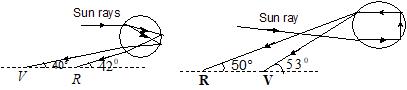
Primary rainbow (a) Secondary rainbow (b)
Scattering of Light: If the molecules of a medium, after absorbing incoming radiations
9: Ray Optics and Optical Instruments
(light), emit them in all possible directions, this process is called scattering. In scattering, if the wavelength of radiation remains unchanged, the scattering is called elastic, otherwise it is inelastic.
scattered light
Medium incidentlight
elasticscattering
Elastic scattering
According to Rayleigh, in case of elastic scattering of light by the molecules, the amount of light scattered depends on both nature of molecules and wavelength of light. Light of shorter wavelength is scattered much more than light of longer wavelength.
Intensity of scattered light
4 1 ∝ λ
Therefore, blue wavelength is scattered most while red is scattered least. Rayleigh scattering takes place when the size of the scatter (say a), is much less than the wavelength of light ( λ ), i.e, a < < λ . At large scattering objects (dust or water), all wavelengths are scattered nearly equally.
Regarding scattered light:
1. Visibility of an object from all directions is due to scattering of light.
2. Scattered light is plane polarized.
3. Under specific conditions, light can also suffer inelastic scattering from molecules (particles like dust and water droplets), in which its wavelength changes. This effect is called Raman effect.
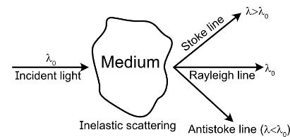
4. Scattering explains the blue colour of the sky. When white light from the sun enters the earth’s atmosphere, scattering takes place, and as light scattered is proportional to 4 1
, blue is scattered the most. When we look at the sky we receive scattered light, which is rich in blue, and the sky appears blue.
5. At sunset or sunrise, the sun rays have to pass through a large distance in the atmosphere. Most of the blue and other shorter wavelengths are removed by scattering. The least scattered light reaching our eyes is red. Therefore, the sun looks reddish. This explains the reddish appearance of the sun and full moon near the horizon.
9.6 OPTICAL INSTRUMENTS
Optical instruments are used primarily to assist the eye in viewing the object. Optical instruments are classified into three groups:
i) Visual instruments
ii) Photographing and projecting instruments
Example: Cameras
iii) Analysing and measuring instruments
Example: Spectrometer
Optical instruments, such as telescopes and microscopes, have one object lens and one eye lens. The lens towards the object is called objective and the lens towards eye is called eyepiece. Single lens forms images with defects (aberrations). If the eye is placed near to the eye lens, it will not receive marginal rays of the eye lens. This reduces the field of view and the intensity is not uniform in the field of view, the central part being brighter than the marginal part.
So, in designing telescopes and microscopes for practical purposes, a combination of lenses are used for both objective and eye lenses to minimize aberrations. A combination of lenses
used as an eye lens is known as eyepiece. In any eyepiece, the lens near to the object is called field lens and the lens near to the eye is called eye lens. The field lens increases the field of view and the eye lens acts as a magnifier. We consider two eyepieces namely Ramsden’s eyepiece and Huygen’s eyepiece.
9.6.1 The Eye
The light enters the eye through a curved front surface, called cornea, and passes through the pupil, which is the central hole in the iris. The size of pupil can be changed by the control muscles. The cornea-lens-fluid system is equivalent to single converging lens. The light is focused by the lens on retina which is a film of nerve fibres. The retina contains rods and cones, which sense the light intensity and colour, respectively. The retina transmits electrical signals to the brain through the optic nerve.
The shape (curvature) and focal length of the eye lens may be adjusted by the ciliary muscles. The image formed by this eye lens is real, inverted and diminished at the retina.
The size of the image on the retina is roughly proportional to the angle subtended by the object on the eye. This angle is known as the visual angle. Therefore, it is known as the angular size.
When the object is distant, its visual angle θ and hence, image at retina, is small and object looks smaller.
When the object is brought near to the eye, its visual angle θ’ and hence, size of image, will increase and the object looks larger, as shown in figure (b).
Optical instruments are used to increase this visual angle artificially in order to improve the clarity. Example Microscope, telescope
When the eye is focused on a distant object (0) θ≈ , the ciliary muscles are relaxed so that the focal length of the eye-lens has maximum value, which is equal to its distance from the retina.
When the eye is focused on a closer object ( θ increases) the ciliary muscles of the eye are strained and the focal length of eye lens decreases. The ciliary muscles adjust the focal length in such a way that the image is again formed on the retina and we see the object clearly. This process of adjusting the focal length is called accommodation.
If the object is brought too close to the eye, the focal length cannot be a adjusted to form the image on the retina. Thus, there is a minimum distance for the clear vision of an object.
The nearest point at which an object is seen clearly by the eye is called the near point of the eye and the distance of near point from the eye is called the least distance of distinct vision . It is equal to 25 cm for normal eye, and it is denoted by D.
The farthest point from an eye at which an object is distinctly seen is called far point and for a normal eye, it is theoretically at infinity.
Defects of Vision
Our eyes are marvellous organs that have the capability to interpret incoming electromagnetic waves as images through a complex process. But our eye may develop
some defects due to various reasons. Some common optical defects of the eye are myopia, hypermetropia, and presbyopia.
Myopia
The light from a distant object arriving at the eye lens may be converged at a point in front of the retina. This defect is called myopia or short-sightedness. In this defect, the far point of the eye is at a distance lesser than infinity, and distant objects are not clearly visible.
Defected eye Corrected eye
This defect is rectified by using spectacles having divergent lens (concave lens) which forms the image of a distant object at the far point of the defected eye. From lens formula,
N.P. = Near Point of defected eye
If the objective is placed at D =25 cm = 0.25 m,
where FP = Far point of defected eye. If the object is at infinity,
Power of lens (P) = 11 fFP =−
Hypermetropia
The light from an object at the eye lens may be converged at a point behind the retina. This defect is called hypermetropia or farsightedness. In this type of defect, near point is at a distance greater than 25 cm and near objects are not clearly visible.
Defected eye Corrected eye
This defect is rectified by using spectacles having convergent lens (i.e. convex lens) which forms the image of near objects at the near point of the defected eye (which is more than 25 cm).
Presbyopia
The power of accommodation of eye lens may change due to the decreasing effectiveness of ciliary muscles. So, far point is lesser than infinity and near point is greater than 25 cm, and both near and far objects are not clearly visible. This defect is called presbyopia. This defect is rectified by using bifocal lens.
Astigmatism
This defect arises due to imperfect spherical nature of lens, the focal length of eye lens in two orthogonal directions becomes different, and the eye cannot see objects in two orthogonal directions clearly, simultaneously. This defect is remedied by cylindrical lens in a particular direction.
Q. a) The far point of a myopic person is 80 cm in front of the eye. What is the power of the lens required to enable him to see very distant objects clearly?
b) In what way does the corrective lens help the above person? Does the lens magnify very distant objects? Explain carefully.
c) The above person prefers to remove his spectacles while reading a book. Explain why.
Sol: a) ,80.08,?uvmf =∞=−==
b) No, the corrective lens is concave and, in fact, it reduces the size of the image. The eye is able to see distant objects not because the corrective lens magnifies the object, but because it brings the object (i.e., it produces A virtual image of the object) at the far point of the eye, which can then be focused on by the eye lens on the retina.
c) The myopic person may have a normal near point i.e., about 25 cm (or even less). In order to read a book with his spectacles (for distant vision), he must keep the book at a distance greater than 25 cm so that the image of the book by the concave lens is produced not closer than 25 cm. As the angular size of the book at a distance >25 cm is less than the angular size at 25 cm, the person prefers to remove his spectacles while reading.
Q. a) The near point of a hypermetropic person is 75 cm from the eye. What is the power of the lens required to enable the person to clearly read a book that is held at a 25 cm distance from the eye?
b) In what way does the corrective lens help the above person? Does the lens magnify the objects held near the eye?
c) The above person prefers to remove the spectacles while looking at the sky. Explain why.
Sol: a ) u = 0.25m ; v = 0.75 m ; f =?
2.67
b) The corrective lens produces a virtual image (at 75 cm) of an object at 25 cm. The angular size of this image is the same as the object. In this sense, the lens does not magnify the object but merely brings the object to the near point of the hypermetropic eye, which then gets focused on the retina.
c) A hypermetropic eye may have normal far point, i.e., it may have enough converging power to focus parallel rays from infinity on the retina of the shortened eyeball. Wearing spectacles
of the converging lenses (used for near vision) will amount to more converging power than needed for parallel rays. Therefore, distant objects may get focused in front of the retina, appearing blurred. Hence, the person prefers not to use the spectacles for distant objects.
Try yourself:
A far-sighted person cannot focus distinctly on objects closer than 1 m. What is the power of lens that will permit him to read from a distance of 40 cm?
Ans: 1.5D
9.6.2 Simple Microscope
To view an object with the naked eye, the object must be placed between D and infinity. The maximum angle is subtended when it is placed at D.
Fig 12.3
This angle can be further increased if a converging lens of short focal length is placed just in front of the eye. The lens used for this purpose is called simple microscope or a magnifier. It is also known as magnifying glass or reading lens. A simple microscope consists of a convex lens of short focal length, and it is fitted in a metal frame with a handle.
The ray diagram of simple microscope is as shown in figure (b). The object is placed at a distance ‘u’ from the lens between pole and focus of lens. The image formed by it is erect, virtual, enlarged and on the same side of the lens between the object and infinity, as shown in the figure (b).
Eye
Unaided - eye
Fig (a)
Eye with instrument Fig. (b)
Magnifying Power of a Simple Microscope
The magnifying power or angular magnification of a simple microscope is defined as the ratio of visual angle with instrument to the maximum visual angle for unaided eye when the object is at the least distance of distinct vision.
Mvisualangle =
withinstrument maximumvisualangleforunaidedeye
Form the above figures, ,0 hh vD ′ θ=θ= .......... (1)
But ∆POO’ and ∆PII’ are similar triangles
fig(b) tanisverysmall tan h v ′ θ=θ θ≈θ
So, hh vu ′ θ== .......... (2)
Now 0 h u h D M θ == θ ; D M u =
Key Insights:
■ In terms of focal length of lens 111 fvu =−
But f is +ve, v is –ve, u is –ve
so, 111111 fvuufv =−⇒=+ +−− so 11 ; DDD MDM ufvfv
Case-I:
When the final image is formed at far point or when the final image is formed at infinity:
In this case, u = f, V =∞ so, D M f ∞ =
Here as u is maximum, magnifying power is minimum and, in this situation, parallel beam of light enters the eye, the eye is least strained and it is said to be normal, relaxed or unstrained.
Case-II:
When the final image is formed at near point or when the final image is formed at D:
v = – D, u is –ve 111111 ; fDuufD =−−=+ 11 D MD fD =+ ; 1 D D M f =+
As the minimum value of v (= D) in this situation, u is minimum and magnifying power is maximum, and the eye is under maximum strain.
Key Insights:
■ If the lens is kept at a distance a from the eye, then D is replaced by (D – a).
1; D DaDa MM ff ∞ =+=
Some important points regarding microscope
i) As 1, D DD MM ff ∞ =+= , so D MM ∞ >
ii) As 1, D DD MM ff ∞ =+= , so, smaller
the focal length of the lens, greater is the magnifying power of the simple microscope.
iii) With increase in wavelength of light used, focal length of microscope will increase and hence, magnifying power will decrease.
iv) The maximum possible magnifying power of a simple microscope for a defect-free image is about 4, which is denoted by 4 x.
v) As we use single lens in microscope, the image formed by a single lens possesses several defects, like spherical aberration and astigmatism, and at larger magnifications, the image becomes too defective.
vi) For higher magnifying power, we cannot use simple microscope. This is because, at larger magnifications, the image becomes too defective. So, we use compound microscope for higher magnifying power.
vii) Simple magnifier is an essential part of most optical instruments, such as microscope or telescope, in the form of an eye piece.
Q. A man with normal near point (25 cm) reads a book with small print, using a magnifying glass, a thin convex lens of focal length 5 cm.
a) What is the closest and farthest distance at which he can read the book when viewing through the magnifying glass?
b) What is the maximum and minimum magnifying power possible using the above simple microscope?
Sol: a) As for the normal eye, far and near points are ∞ and 25 cm, respectively,
so, for magnifier max v =−∞ and vmin= – 25 cm
However, for a lens, as 111 vuf −=
i.e., (/)1 uf fv = , So u will be minimum
when vmin = – 25 cm, i.e., min ()5254.17cm (5/25)16 u ===−
and u will be maximum when v max = ∞ i.e., max ()55cm (5/)1 u ==− ∞−
So, the closest and farthest distances of the book from the magnifier (or eye) for clear viewing are 4.17 cm and 5 cm, respectively.
b) In case of simple magnifier, MP = (D/u). So, MP will be minimum when u max = 5 cm
i.e., min 25 ()5 5 D MP f ===
MP will be maximum when umin = (25/6) cm max ()2561 (25/6) D MP
Try yourself:
If the focal length of a magnifier is 5 cm, calculate (a) the power of the lens, (b) the magnifying power of the lens for relaxed and strained eye.
Ans: (a) 20D (b) 6
9.6.3 Compound Microscope
A simple magnifying lens is not useful where large magnification is required. A highly magnified image must be produced in two stages. A compound microscope is used for that purpose. Figure shows a simplified version of a compound microscope and ray diagram for image formation.
It consists of two convergent lenses arranged coaxially. The one facing the object is called the objective and the one close to the eye is called eye piece. The objective has a small aperture and smaller focal length than those of the eyepiece, so that the image is free from defects. The lenses are fitted at the ends of a metal tube. The separation between the
objective and the eyepiece can be varied by means of a rock and p inion arrangement.
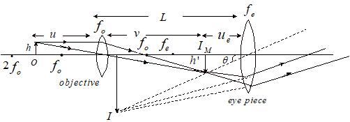
The object is placed between fo and 2fo of the objective, so that image ( I M) formed by the objective is inverted, real, enlarged and at a distance v (> 2 fo) on the other side of the lens. This image IM acts as the object for eye piece and is within its focus. So the eyepiece forms the final image (I) which is erect, virtual and enlarged, with respect to IM. So, the final image I, with respect to object, is inverted, virtual, enlarged and at a distance D to ∞ from the eyepiece.
Magnifying Power
Visualanglewithinstrument
Max.visualangleforunaidedeye
If the size of the object is h and least distance of distinct vision is D , then from the above figures,
where u is object distance for the objective lens, v is image distance for the objective lens, u e is the object distance for eyepiece.
As 0 v m u = and e e D m u = ,
So, magnifying power of compound microscope is also equal to product of linear magnification of objective and angular magnification of eyepiece.
i.e., M = m0 × m e
The length of the tube L = v + u e
Case-I:
If the final image is formed at infinity (far point):
In this case, u e = fe
But for objective linear magnification, (m0) = ' vh uh −= ; So e
with L ∞ = v + fe
A microscope is usually considered to operate in this mode unless stated otherwise. In this mode, u e is maximum and hence magnifying power is minimum.
Key Insights:
■ When the object is very close to the principal focus f0 of the objective, the image due to the objective becomes very close to the eyepiece. Then, replace u with f0 and v0 with L, so the expression for magnifying power, 0 e LD M ff
Case-II:
If the final image is formed at D (near point): In this case, for eye piece V e = –D, u e is –ve.
In this situation, as u e is minimum, magnifying power is maximum and eye is most strained.
When the object is very close to the principal focus f0 of the objective, the image due to the objective becomes very close to the eyepiece. Then, replace u with f0 and v0 with L, so the expression for magnifying power,
Q. A microscope consists of two convex lenses of focal lengths 2 cm and 5 cm placed 20 cm apart. Where must the object be placed so that the final virtual image is at a distance of 25 cm from the eye?
Sol: For the eyepiece, focal length f = fe = +5 cm; v = v e = – 25 cm; u = u e =?
Substituting these values in 111 fvu =−⇒
e u
25 cm, 6 e u =−
Some important points regarding compound microscope:
i) As magnifying power of a compound micro-scope is negative, the image seen is always truly inverted.
ii) For a microscope, magnifying power is minimum when final image is at ∞ and maximum when final image is at least distance of distinct vision D,
i.e., and
iii) For a given microscope, magnifying power for normal setting remains practically unchanged if field and eye lenses are interchanged, as
iv) In an actual compound microscope, the objective and eyepiece each consist of a combination of several lenses instead of a single lens to eliminate the aberrations and increase the field of view.
v) In low power microscopes, the magnifying power is about 20 to 40, while in high power microscopes, the magnifying power is about 500 to 2000.
Object for the eyepiece is to be at a distance of 25 6 cm to its left.
But v0 + u e = 20 cm, where u e = 25 6 cm 0 2595 2020cm 66 e vu=−=−=
For the objective, v = v0 = + 95 cm 6 ; f = f0 = + 2 cm ; u =? 111 fvu =− ; 161 295 u =−
16183190 ;2.29cm. 95219083 u u =−=−=−=−
The object is to be placed at a distance of 2.29 cm to the left side of the objective.
Q. A compound microscope has a magnifying power of 30. The focal length of its eyepiece is 5 cm. Assuming the final image to be at the least distance of distinct vision (25 cm), calculate the magnification produced by the objective.
Sol: In case of compound microscope, 0 e Mmm =× ............ (1)
In case of final image at least distance of distinct vision, 1 e e D m f =+
.......... (2)
So, from eq. (1) and (2),
Here, M = –30; D = 25 cm and f e = 5 cm
So, 0 25 301 5 m −=+ ,
i.e., 0 30 5 6 m ==− .
Negative sign implies that image formed by objective is inverted.
Try yourself:
Find the magnifying power of a compound microscope whose objective has a focal power of 100 D and eyepiece has a focal power of 16 D, when the object is placed at a distance of 1.1 cm from the objective. Assume that the final image is formed at the least distance of distinct vision, 25 cm.
Ans: –50
9.6.4 Telescopes
A microscope is used to view the objects placed close to it. To look at distant objects, such as a star, a planet or a cliff, we use another optical instrument called telescope, which increases the visual angle of a distant object.
The telescope that uses a lens as an objective is called refracting telescope. However, many telescopes use a curved mirror as an objective and such telescopes are known as reflecting telescopes. There are three types of reflecting telescopes in use.
i) Astronomical telescope
ii) Terrestrial telescope
iii) Galilean telescope
iv) Reflecting Telescope
Astronomical Telescope
The figure given below shows the construction and working of an astronomical telescope. It consists of two converging lenses. The one
facing the object is called objective and has larger focal length and aperture while the other facing the eye is called eyepiece and has small focal length and aperture. Principal axis is common for both objective and eyepiece. The objective is fitted at one end of a metal tube. The eyepi ece is fitted at the end of another metal tube. The metal tubes are placed one inside the other and the position of the eyepiece can be adjusted by rack and pinion arrangement.
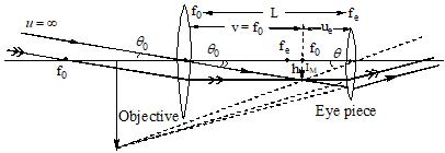
As a telescope is used to see distinct objects, in it, object is between ∞ and 2f0 of objective and hence, image ( I M) formed by objective is real, inverted and diminished and it is between f o and 2f o on the other side of it. This intermediate image (IM) acts as an object for eyepiece and it is within the focus fe. So, final image (I) with respect to IM is erect, virtual, enlarged and at a distance D to ∞ from the eye. This, in turn, implies that final image (I) with respect to object is inverted, enlarged and at a distance D to ∞ from the eye.
Magnifying Power (M)
Magnifying power of a telescope is given by 0 anglewithinstrument Visualangleforunaidedeye
From the above figure,
The length of tube L = fo + u e.
Case-I:
If the final image is at infinity (far point):
In this case, for eyepiece e v =−∞ , u e = –ve
eeuf −= −∞−
Hence, u e = fe
Hence, 0 e Mf f ∞ =− and L ∞ = fo + fe
Usually, a telescope is operated in this mode unless stated otherwise. In this mode u e is maximum, and hence, magnifying power is minimum, while length of tube is maximum.
This case is also called normal adjustment because, in this case, eye is least strained or it is relaxed.
Case-II:
If the final image is at D (near point):
In this situation, for eyepiece, v e = –D
i.e.,
In this case, length of the tube
In this situation, u e is minimum, and hence, magnifying power is maximum while the length of the tube is minimum and the eye is most strained.
Some important points regarding astronomical telescope:
i) In case of telescope, if object and final image
are at infinity and total light entering the telescope leaves it, parallel to its axis, as shown,
where A 0 and A e are the apertures of objective and eyepiece.
ii) As magnifying power is negative, the image seen in astronomical telescope is truly inverted i.e., left is turned right with upside down simultaneously. However, as most of the astronomical objects are symmetrical this inversion does not affect the observations.
iii) For a given telescope, magnifying power is minimum when final image is at infinity (far point) and maximum when it is at least distance of distinct vision (near point), i.e.,
iv) In case of a telescope when the final image is at ∞ , if field and eye lenses are interchanged, magnifying power will change from
to
, i.e., it will change from m to 1 m
, i.e., it will become
times of its initial value.
v) As magnifying power for normal setting is 0 e f
, to have large magnifying power, f0 must be as large as practically possible and
fe must be small. This is why in a telescope, objective is of large focal length while eyepiece is small.
vi) Larger aperture of objective helps in improving the brightness of image by gathering more light from the distant object. However it increases aberrations, particularly spherical ones.
vii) If a fly is sitting on the objective of a telescope and we take a photograph of distant astronomical object through it, the fly will not be seen but the intensity of the image will be slightly reduced as the fly will act as obstruction to light and will reduce the aperture of the objective.
viii) A telescope produces angular magnification whereas a microscope produces linear magnification. The image due to a telescope appears to be near to the eye, increasing the visual angle.
Q. The diameter of the moon is 3.5 × 10³ km and its distance from the earth is 3.8 × 10⁵ km. It is seen through a telescope having focal lengths of objective and eyepiece as 4m and 10 cm, respectively. Calculate (a) magnifying power of telescope, (b) length of telescope tube and (c) angular size of image of moon.
Sol: For normal adjustments,
a) 04100 10 e Mf f × == = 40
b) L = f0 + f e = 400 + 10 = 410 cm = 4.10 m
c) As the angle subtended by the moon on the objective of telescope
Try yourself:
A telescope objective of focal length 1 m forms a real image of the moon which is 0.92 cm in diameter. Calculate the diameter of the moon, taking its mean distance from the earth to be 38 x 104 km. If the telescope uses an eyepiece of 5 cm focal length, what would be the distance between the two lenses for (i) the final image to be formed at infinity (ii) the final image (virtual) at a distance of 25 cm from the eye.
Ans: (i) 105 cm (ii) 104.2 cm
Terrestrial
Telescope
In an astronomical telescope, the final image is inverted with respect to object. This creates some practical difficulty if the telescope is used to see earthly objects. To remove this difficulty a convex lens of small focal length ‘f’ is placed at a distance ‘2f’ from the intermediate image formed by field lens. It will erect the intermediate image at a distance ‘2f’ on the other side of it and this image will act as an object for eye lens.
Now, the final image will be erect with respect to object, as shown in figure. This lens is called erecting lens and for it, m = –1.
i.e.,
, the angular size of final image
Fig 12.7
(i) The magnifying power and length of telescope for relaxed eye will be
(ii) The magnifying power and the length of telescope for image at D will be
Q. A telescope has an objective of focal length 50cm and an eyepiece of focal length 5cm. The least distance of distinct vision is 25cm. The telescope is focused for distinct vision on a scale 2 m away from the objective. Calculate (a) magnification produced and (b) separation between objective and eye piece.
Sol: Given, fo = 50 cm and fe = 5 cm
For objective:
0 111 20050 v −= ,
0 1200 3 cm v ∴=
0 0 0 (200/3)1 2003 v m u ===−
For eyepiece : 111 255 e u −= , 25 6 e ucm∴=− and 25 6 (25/6) e e e v m u ===
a) Magnification, 02 e mmm=×=−
b) Separation between objective and eyepiece,
0 20025425 70.83cm 366 e Lvu=+=+==
Try yourself:
A 100 m tall tower at a distance of 3 km is seen through a telescope having objective of focal length 140 cm and eyepiece of focal length 5 cm. What is the size of the final image, if it is 25 cm from the eye?
Ans: –28 cm
Galilean Telescope
In this telescope a concave lens is used as eyepiece ray diagram is as shown below.
f0 = focal length of objective
fe = focal length of eyepiece
θ0 = angle subtended by the object at eyes = 0 ' h f
θ0 = angle subtended by final image at eyes
= ' . e h u
If final image is formed at least distance of distinct vision, then for the eyepiece,
From equations (1) and (20),
For normal adjustment L
Galilean telescope has a shorter tube length.
Q. The focal lengths of objective lens and eye lens of a Galilean telescope are respectively 30 cm and 3 cm. The telescope produces virtual erect image of an object situated for away from it, at least distance of distinct vision from the eye lens. In this condition, find the magnifying power of the Galilean telescope.
Sol:
Reflecting Telescope
Cassegrain’s telescope
The telescope in which the objective is a curved mirror is called “reflecting telescope”. This type of telescope is lightweight, portable, low cost and easy-to-handle. The image formed by it is more bright and free from chromatic aberration. By using parabolic mirror instead of spherical mirror, spherical aberration can also be eliminated.
One obvious problem with a reflecting telescope is that the objective mirror focuses the light inside the telescope tube so another convex mirror is placed inside the tube to focus the incident light on the eyepiece. The light rays from a distant star, after reflection from concave mirror ‘A’, fall on the convex mirror B and are allowed to converge at the convex lens acting as the eyepiece.
i) In reflecting telescopes, no absorption of light as in lenses.
ii) Mirrors can be constructed with considerable large diameters than lenses.
iii) Mirrors are free from chromatic and spherical aberrations.
Key Insights:
■ The latest telescope in India in Kavalur, Tamil Nadu, is a 2.34 m diameter Cassegrain telescope.
■ The largest telescope in the world is the pair of Keck telescopes in Hawaii (USA) with a reflector of 10 m diameter.
TEST YOURSELF
1. A person can see clearly up to 1 m. Find the nature and power of the lens which will enable him to see things at a distance of 3 m.
(1) concave, –0.66 D
(2) convex, +0.66 D
(3) concave, –0.33 D
(4) convex, +0.33 D
2. The far point of a myopic eye is 10 cm from the eye. What must be the focal length of a lens for reading at normal distance (25 cm)?
(1) – 8.35 cm (2) – 16.7 cm
(3) – 35.4 cm (4) – 32.7 cm
3. The far point of a shortsighted woman is 75 cm from the eye. What focal length lens should the woman use in order to focus on a very distant object (U=∞)? Also find power of the lens?
(1) –1.33 D (2) –2.33 D
(3) –3.4 D (4) –1.9 D
4. A person wears eyeglasses of focal length –80 cm. Where is the far point of the person?
(1) 80 cm from the eye
(2) 90 cm from the eye
(3) 70 cm from the eye
(4) 60 cm from the eye
5. For a person, near point of vision is 100 cm. Then the power of lens, he must wear so as to have normal vision, should be
(1) + 1 D
(2) – 1 D
(3) + 3 D
(4) – 3 D
6. If your eyeglasses have f = 60 cm, what is your near point?
(1) 43 cm
(2) 34 cm
(3) 46 cm
(4) 36 cm
7. The maximum magnification that can be obtained with convex lens of focal length 2.5 cm is (the least distance of distinct vision is 25 cm)
(1) 10 (2) 0.1
(3) 62.5 (4) 11
8. The objective lens of a compound microscope produces magnification of 10. In order to get an over all magnification of 100 when image is formed at 25 cm from the eye, the focal length of the eye lens should be (in cm)
(1) 4 (2) 10
(3) 25/9 (4) 9
9. There are four lenses A , B , C and D of power +100 D, –50 D, 20 D and 5 D respectively. Which lenses will you use to design a compound microscope for best magnification?
(1) A and C (2) B and D
(3) C and D (4) A and B
10. A microscope consists of two convex lenses of focal lengths 2.0 cm and 6.25 cm placed 15.0 cm apart. Where must the object be placed so that the final virtual image is at a distance of 25 cm from the eye?
(1) 2.5 cm (2) 2 cm
(3) 1.5 cm (4) 3 cm
11. The two lenses of a compound microscope are of focal lengths 2 cm and 5 cm. If an object is placed at a distance of 2.1 cm from the objective of focal length 2 cm the final image forms at the least distance of distinct vision of a normal eye. Find the distance between the objective and eyepiece.
(1) 46.17 cm (2) 42 cm
(3) 4.17 cm (4) 40 cm
12. In a compound microscope the focal length of objective lens is 1.2 cm and focal length of eye piece is 3.0 cm. When object is kept at 1.25 cm in front of objective, final image is formed at infinity. Magnifying power of the compound microscope should be
(1) 150 (2) 200
(3) 400 (4) 100
13. An astronomical telescope has an angular magnification of magnitude 5 for distant objects. The separation between the objective and the eyepiece is 36 cm and the final image is formed at infinity. The focal length f0 of the objective and the focal length fe of the eyepiece are
(1) f0 = 45 cm, fe = –9 cm
(2) f0 = 7.2 cm, fe = 5 cm
(3) f0 = 50 cm, fe = 10 cm
(4) f0 = 30 cm, fe = 6 cm
14. If tube length of astronomical telescope is 105 cm and magnifying power is 20 for normal setting, the focal length of the objective is
(1) 100 cm (2) 10 cm
(3) 20 cm (4) 25 cm
15. The focal lengths of the eyepiece and the objective of an astronomical telescope are 2 cm and 100 cm, respectively. Find the magnifying power of the telescope for normal adjustment and the length of the telescope.
(1) –50 ; 102 cm
(2) –100 ; 204 cm
(3) 25 ; 62 cm
(4) 25 ; 62 cm
16. A telescope has an objective lens of focal length 150 cm and an eyepiece of focal length 5 cm. If a 50 m tall tower at a distance of 1 km is observed through this telescope in normal setting, the angle formed by the image of the tower is θ, then θ is close to (1) 1°
(2) 60°
(3) 1.5 rad
(4) 30°
17. The focal length of the objective and the eye-piece of a telescope are 50 cm and 5 cm respectively. If the telescope is focused for distinct vision on a scale distant 2 m from its objective, then its magnifying power will be
(1) –4 (2) –8 (3) +8 (4) –2
Answer Key
(1) 1 (2) 2 (3) 1 (4) 1
(5) 3 (6) 1 (7) 4 (8) 3
(9) 1 (10) 1 (11) 1 (12) 2
(13) 4 (14) 1 (15) 1 (16) 2 (17) 4
9.7 ABERRATIONS
The theory of image formation for mirrors and lenses includes various approximations. The lens formula used to know the image formation is applicable for paraxial light rays or for the rays making small angles with the optic axis. Due to these approximations, the image formed by an optical system is usually imperfect. The imperfections or defects of images are called aberrations. These defects of images are not due to lenses but due to the formulae that we use. If the defect in image is due to light, i.e., when an object is illuminated by white light, the image formed is coloured, then the aberration is called chromatic aberration. If the defect in image is due to optical system, it is called monochromatic aberration. Monochromatic aberration is of many types, such as spherical, coma, distortion, curvature and astigmatism. We shall limit ourselves to chromatic and spherical aberrations only.
9.7.1
Chromatic Aberration
i) The image of an object formed by a lens when the object is illuminated by white light is usually coloured and blurred. This defect of image is called chromatic aberration and arises due to the fact that focal length of lens is different for different colours.
ii) We know that the focal length of lens is given by () 12 111 1 fRR
iii) The focal length of lens depends on ‘θ’. The refractive index µ of lens is maximum for violet and minimum for red. Hence, when a parallel beam of white light is incident on a convex lens, violet rays are brought to focus at fv near the lens, and red rays are brought to focus at fr far away from lens. All the other rays are brought to focus between them.
iv) The difference between f v and f r is a measure of longitudinal chromatic aberration or axial chromatic aberration.
v) When the object is at infinity, the longitudinal chromatic aberration = fr – fv = – df
(where df = fv – fr)
We know 12 111 (1) fRR
=µ−−
....... (1)
Differentiating the above equation, 2 12 11 dfd fRR ⇒−=µ− 2 1 (1) dfd ff⇒−=µ× µ−
(Since 12 111 (1) RRf −= µ− ) (1) dfd f ⇒−=µ µ− ; But 1 d µ =ω µ− , where ω is dispersive power of material of the lens df f ⇒−=ω dff ⇒−=ω
Hence, longitudinal chromatic aberration (when the object is at infinity) = – df = ω f
vi) whitelight
Circle of least confusion
When a point object on the axis of lens is illuminated by white light, the image formed is coloured and spread along the axis from IV to IR, as shown in the above figure. If a screen is placed perpendicular to the principal axis at I R , the image is in the form of a circle with red center, and periphery violet and the remaining colours between them. If the screen is at IV, the centre of the circle is of violet colour, periphery is red and the remaining colours are between them. In between IV and IR, there is a circular patch, which has almost uniform intensity of different colours. This circle has least size and it is nothing but the circle of least confusion. It is the nearest approach to a point image of a point object.
vii)
For an extended object, the images formed by light rays of different colours are of different sizes.
The separation between the images formed by extreme colours of visible light, i.e., X, is called the axial or longitudinal chromatic aberration.
The difference in the sizes of the images formed by extreme colours of visible light i.e., Y, is called the transverse or lateral chromatic aberration.
viii)
Chromatic aberration is taken to be positive for convex lens because the focus for the red colour is to the right of violet colour.
Chromatic aberration is taken to be negative for concave lens because the focus for the violet colour is to the right of red colour.
Methods to Reduce Chromatic Aberrations
We cannot have a single lens free from chromatic aberration. We have to use a combination of two lenses to minimise chromatic aberration.
i) A converging lens of smaller focal length f1 and small dispersive power ω 1 (crown glass) and a diverging lens of longer focal length and longer dispersive power ω2 (flint glass) are kept in contact to reduce the chromatic aberration. This combination is called achromatic doublet. It satisfies the condition, 12 12 0 ff ωω +=
ii) In case of two thin lenses separated by a distance (d), the condition of achromatism is 1221 12 ω+ω = ω+ω dff
In case of two thin lenses made from the same material (ω1=ω2), for the condition of achromatism, the distance of separation between them is 12 12 ,() 2 + =ω=ωdff .
9.7.2 Spherical Aberration
In case of convex lens, the focus for marginal rays (Fm) is to the left of the focus for paraxial rays ( F p). So, the spherical aberration produced by a convex lens is to be taken as positive.
iv) In case of concave lens, the focus for marginal rays ( F m ) is to the right of the focus for paraxial rays ( F p). So, the spherical aberration produced by a concave lens is to be taken as negative.
i) When a point source O of monochromatic light is placed on the axis of a lens, the rays incident near the axis (called paraxial rays) are brought to focus at IP, while the rays passing through the marginal portions of the lens (called marginal rays) are brought to focus at IM, near the lens. The intermediate rays are focused between IM and I P. The inability of the lens to form a point image of an axial point object is called spherical aberration.
ii) If a screen is placed perpendicular to the principal axis at IP, the image is in the form of a circle with a bright centre and the intensity gradually decreases towards the edge. As the screen is moved towards the lens, the intensity at the centre decreases and at the edge increases. When the screen is at IM, the centre is faint and the outer edge is bright. In between, there will be a circular patch of light of almost uniform intensity. This circle is called the circle of least confusion, as shown in the f igure. It is the nearest approach to a point image of a point object. The radius of the circle of least confusion is a measure of lateral or transverse spherical aberration.
v) Spherical aberration arises due to large aperture and spherical nature of lens. Due to spherical nature, angle of prism A will be different for different parts of a lens, being maximum for marginal portion and minimum for paraxial, and as δ∝(µ−1) A deviation is maximum for marginal rays and minimum for paraxial rays, as shown in the figure.
Fp Fm
vi) The spherical aberration produced by a lens depends on the distance of the object point and varies approximately as the square of the distance of the object ray above the axis of the lens.
vii) As spherical aberration arises due to spherical nature of a lens, it can never be eliminated, but it can be minimised by the following methods.
Methods to Reduce Spherical Aberration
i) Spherical aberration of a lens depends on its aperture, and it occurs only when the aperture of lens is large. A simple method to reduce this defect is to decrease the effective aperture of the lens by using a stop. By using stops, either paraxial or marginal rays are cut off, bringing the rest practically to one focus. However, the amount of light passing through lens is reduced. Hence the image is less bright.
is brought about gradually and by equal amounts at a large number of refracting surfaces, the spherical aberration can be minimised.
Crossed lens: A lens with a specific choice of radii of curvature to bring about equal deviation at the two surfaces, such that spherical aberration reduces, is called a crossed lens.
Example 1: For crown glass of refractive index 1.50 the crossed lens for parallel rays is a convex lens of radii of curvature in the ratio 1 : –6 with the more curved surface facing the incident light.
Example 2: For flint glass of refractive index 1.60, the crossed lens for parallel rays is planoconvex, with the convex surface facing the incident rays.
ii) (a) Spherical aberration can be minimised by affecting the total deviation of marginal rays. If the total deviation of marginal rays
surface towards incident rays
If the plane surface faces the incident rays, there will be no deviation at this surface and the total deviation occurs only at the curved surface. The spherical aberration is maximum. This is shown in figure. Convex surface towards incident rays
When the convex surface faces the incident rays, the deviation is shared at both the surfaces, and hence, both the paraxial and marginal rays are brought to focus at the same point and the defect is minimised.
(b) A system of two convergent lenses of focal lengths f 1 and f 2, separated by a distance equal to the numerical difference between the two focal lengths, can be used to minimise spherical aberration. The reason is that the system gives equal increments of deviation to light rays that are initially parallel to the principal axis. 12dff =
CHAPTER REVIEW
Reflection of Light
■ If the size of the reflecting surface is less than the wavelength of incident light, then diffused reflection takes place.
■ Angle of deviation of reflected ray is δ = ( π –2i)
■ In case of reflection at a plane mirror, if the mirror rotates through an angle θ clockwise, the reflected ray rotates through an angle 2 θ clockwise. For anticlockwise rotation of mirror, the reflected ray also rotates anti-clockwise.
■ If ˆ ei is the unit vector along the incident ray, ˆ r e is the unit vector along the reflected ray and ˆ n is the unit vector along the normal, then ˆˆˆˆˆ 2(.).rii eeenn =− Here ˆ n is directed into the plane of reflection.
■ A plane mirror forms a real image of a virtual object.
■ Two mirrors are inclined to each other at an angle θ . Number of images of a point object formed is determined as follows.
(i) If 2 π / θ is even (= m say ), then number of images is (m–1) for all positions of the object.
(ii) If 2 π / θ is odd and the object is on the bisector of θ , then number of image is (2 π / θ1).
(iii) If 2π/θ is odd and the object is not on the bisector, then number of images is 2 π / θ .
iii) Spherical aberration can also be reduced by using a suitable combination of convex and concave lenses because a convex lens has positive defect and a concave lens has negative defect.
(iv) If 2π/θ is fraction, then number of images is equal to the integral part of 2 π / θ
■ If o V is the velocity of object relative to ground, VM is the velocity of mirror relative to ground, ()11 o V
is the component of velocity of object parallel to the plane of the mirror and () ⊥ VOM is the component of velocity of object relative to mirror normal to the plane of the mirror, then velocity of image relative to ground is given by ()() || IMOOM VVVV ⊥
■ Suppose a plane mirror is mounted on the wall of a hall of height H and length L and an observer is standing on the floor at a distance L / n from the mirror, then minimum length of the mirror for which the person can see the full image of the wall behind him is equal to H/(n+1).
■ Mirror equation for spherical mirror is 1112 vufR +== .
■ For a concave mirror, if u<f than the image formed is virtual, erect and magnified.
■ For a concave mirror, if u = 2 f than the image is formed at the location of the object. It is real, inverted and same sized.
■ For a concave mirror, if 2 f > u > f, image formed is real, inverted and magnified.
■ For a concave mirror if u > 2 f , image formed is real, inverted and diminished.
■ For a convex mirror and real object, image is always virtual, erect and diminished, irrespective of the position of the object.
■ For a spherical mirror, lateral magnification is i o h v m hu ==−
■ For a spherical mirror, longitudinal magnification = (v/u)2= m2 .
■ For a spherical mirror, area magnification of a two dimensional object = m2, where m is lateral magnification.
■ When a point object is moving along the principal axis of a spherical mirror, velocity of image is 2
■ When a point object is projected from the principal axis of a spherical mirror in a direction perpendicular to the principal axis, then velocity of image is VI = –mVo, where m is lateral magnification.
Refraction of Light at Plane Surface
■ When a ray of light is travelling from medium 1 to medium 2, by Snell's law, µ 1 sin i1 = µ2 sin i2.
■ From Snell's law, sin i 1/ v 1 = sin i 2/ v 2 and sin i1 / λ 1 = sin i2 / λ 2
■ Vector form of Snell's law, ()() 122
enµen µ×=×
■ Refractive index in a medium is given by µµrr =∈
■ Refractive index of medium 1 relative to medium 2, 122 21 211 === µv µ µv λ λ .
■ If a ray of monochromatic light traverses a length ℓ m in a medium of refractive index µ, then equivalent optical path ℓ o = µ ℓ m .
■ When a ray of light is refracted through a slab of glass of thickness t and refractive index µ, then lateral shift of the incident
ray is s = t sin(i-r)/cos r, where i is angle of incidence and r is angle of refraction.
■ For normal incidence, apparent shift (i) object in denser, observer in rarer, s = (1–1/µ)t. (ii) Object in rarer and observer in denser, S = (µ–1) h
■ When an object is viewed through a transparent slab of refractive index. µ and thickness t, for near normal vision apparent shift s = (1–1/µ)t.
■ When a ray of light travels from a denser medium 1 to a rarer medium 2, the critical angle is given by 11 2 21 1 1 sinsin µ c µµ
■ In an optical fibre when a signal in the form of light is directed at one end of the fibre, the maximum angle of incidence i max for which light will be confined to the core is
122 12 sin iµµ ≤− .
Refraction of Light at Spherical Surfaces and by Lenses
■ Relation between object distance and image distance for refraction at single spherical surface (object is in medium 1 and rays of light emerging from the object is refracted into medium -2, R is the radius of spherical surface) is 2121 −= µµµµ vuR .
■ In the above case, lateral magnification 1 2 = µ v m µu
■ In the above case, longitudinal magnification 2 2 11 22 == L µµ v mm µuµ .
■ In the above case if the object moves along the principal axis with velocity v o, then velocity of image is 2 1 2 . io µ vmv µ = .
■ If the object moves transverse to the principal axis, then image velocity v i = mv o , where 1 2 . µ v m µu = and v o = object velocity.
■ First focal length () 1 1 21 , () =∞=− µR Vf µµ
■ Second focal length () 2 2 21 , () =∞=− µR uf µµ
■ In the above case power of refracting spherical surface is
1221 12 ==−= µµµµ P ffR
■ For a lens if the media on the two sides are the same, then 12ff =
■ General lens formula when media on both sides of lens are different is 3 23 121 12 µ µµ µµµ vuRR
■ In the above case if µ 1 = µ 3 = 1 and µ 2 = µ,general Lens formula is , () 12 11111 1 µ vuRRf
■ Lens maker's formula, () 12 111 1 µ fRR =−−
■ Newton's formula is x1x2 = f1f2, where x1 and x2 are distances of object and image from first focal point and second focal point respectively.
■ In a lens mirror combination, if the final image coincides with the object, then rays of light must be incident on the reflecting surface of the mirror perpendicularly.
■ Velocity component of the image of a moving object along the principal axis of a lens () 2 11 11 ()io v vv u =+
■ Velocity component of the image of a moving object perpendicular to the principal axis of a lens ()()ioo dm vmvh dt ⊥⊥=+ for a particle , h o = 0 and ()() io vmv⊥⊥ =
■ If f 1 and f 2 are the focal length of two lenses(L1 and L2 ) separated by a distance d on common principal axis and F is the equivalent focal length then focal length of the equivalent lens is given by,
1212 111 d
=+−
■ In the above case the distance of equivalent lens from the second lens L2 is Fd/f1 towards the object, if the value is positive and away from the object, if the value is negative.
■ In the above case the distance of the equivalent lens from the first lens L 1 is Fd/f2 away from the object if the value is positive and towards the object if the value is negative.
Prism
■ Angle of deviation of refracted ray = i1+ i2 – A.
■ When i1 = i2, angle of deviation δ becomes minimum.
■ When δ = δ min , min 1 sin() 2 sin 2 A µ A +δ =
■ For thin prism, δ = (µ – 1) A.
■ Angle of deviation δ will be maximum when i1 is maximum i.e., when i1 = 90°
■ Focal length of a silvered lens is given by 121 Ffflm =−+ where fl = focal length of unsilvered lens. fm = focal length of the mirror ( the silvered surface behaves like a mirror).
■ δ max =90°+ 11 1 sinsinsinµAA µ
■ Li ght wi ll emerge from a prism when 11 1 1 sinsinsiniµA µ
■ A ray of light will not emerge out of a prism (whatever be the angle of incidence) is 1 1 2sin A µ >
■ Angle of dispersion for incident white light is given by θ = (µv – µR) A.
■ Mean angle of deviation
■ Dispersive power ( ω )
■ For a chromatic combination of prism, net angle of dispersion is zero.
■ Condition for achromatic combination [(µV)1– (µR)1]A1 = [(µV)2– (µR)2]A2
■ For direct vision combination, net mean deviation is zero.
■ Condition for direct vision Combination
Optical Instruments
■ Magnifying power of a simple microscope
i) M = D / f , when image is formed at infinity.
ii) M = (1+ D/f), when image is formed at least distance for distinct vision.
■ Magnifying power of a compound microscope
i) =−× o oe v D M uf when final image is formed at infinity
here v o = Distance of real image formed by objective
u o = Distance of object from objective
ii) 1 =−+
O Oe v D M uf , When final image is formed at least distance of distinct vision.
■ Magnifying power of an astronomical telescope
i) o e f M f =− , when final image is formed at infinity
Tube length L = ( fo + fe)
ii) 1 oe e ff M fD =−+ , when final image is formed at le ast dista nce of distinct vision. In this case tube length () e oeo e Df Lfuf Df =+=+ +
■ Magnifying power of a Galilean telescope ( Eyepiece is a concave lens).
i) o e f M f =− , when final image is formed at infinity.
Tube length Lffoe =−
ii) 1 e o e f f M fD =−− , when final image is formed at least distance of distinct vision.
In this case tube length =− e o e Df Lf Df
Exercises
NEET DRILL
Reflection of Light
1. Two plane mirrors are arranged at right angles to each other as shown in figure. A ray of light is incident on the horizontal mirror at an angle θ. For what value of θ the ray emerges parallel to the incoming ray after reflection from the vertical mirror?
(1) 60° (2) 30° (3) 45° (4) any value of θ
2. Two plane mirrors are inclined at angle θ as shown in figure. If a ray parallel to OB strikes the other mirror at P and finally emerges parallel to OA after two reflections, then θ is equal to
5. An infinitely long rod lies along the axis of a concave mirror of focal length f. The near end of the rod is at a distance u > f from the mirror. Its image will have a length is equal to.
(1) uf uf (2) uf uf +
(3) 2 f uf + (4) 2 f uf
6. A car is fitted with a convex side-view mirror of focal length 20 cm. A second car at 2.8 m behind the first car is overtaking the first car at a relative speed of 15 m/s. The speed of the image of the second car as seen in the mirror of the first one is
(1) 1 m/s 15 (2) 1 m/s 10
(3) 10 m/s (4) 15 m/s
7. A point object is placed at a distance of 30 cm from a convex mirror of focal length 30 cm. The image will form at
(1) Infinity
(2) Focus
(3) Pole
(4) 15 cm behind the mirror
(1) 90° (2) 60° (3) 45° (4) 30°
3. A watch shows time as 3:25 when seen through a mirror, time appeared will be (1) 8:35 (2) 9:35
(3) 7:35 (4) 8:25
4. A small plane mirror is rotating at a constant frequency of n rotation per second. With what linear velocity (in ms–1) will a light spot move along a spherical screen of radius of curvature of R metres if the mirror is at the centre of curvature of the screen?
(1) 4πnR (2) 2πnR
(3) πnR (4) 4nR
8. An object is placed in-front of a concave mirror of focal length f. A virtual image is formed with a magnification of 2. To obtain a real image of the same magnification, the object has to moved by a distance
(1) f (2) f/2 (3) 3f/2 (4) 2f/3
9. The sun (diameter D) subtends an angle of θ radians at the pole of a concave mirror of focal length f. The diameter of the image of the sun formed by the mirror is
(1) θ f (2) θ2 f D
(3) 2θf (4) Dθ
10. You are asked to design a shaving mirror assuming that a person keeps it 10 cm from his face and views the magnified image of the face at the closest comfortable distance of 25 cm. The radius of curvature of the mirror would then be
(1) 24 cm (2) 30 cm
(3) –24 cm (4) 60 cm
11. An object is placed at a distance of 40 cm from a concave mirror of focal length 15 cm. If the object is displaced through a distance of 20 cm towards the mirror, the displacement of the image will be
(1) 30 cm away from the mirror
(2) 36 cm away from the mirror
(3) 36 cm towards the mirror
(4) 30 cm towards the mirror
Refraction of Light at Plane Surface
12. A glass slab of thickness 4 cm contains the same number of waves as 5 cm of water when both are traversed by the same monochromatic light. If the refractive index of water is 4/3, then that of glass is (1) 5/3 (2) 5/4
(3) 16/15 (4) 3/2
13. The wavelength of light in vacuum is 5000 Å. When it travels normally through diamond of thickness 1.0 mm, find the number of waves of light in 1.0 mm of diamond. (Refractive index of diamond = 2.417)
(1) 4834 waves
(2) 5834 waves
(3) 4384 waves
(4) 6834 waves
14. If the angle of incidence is twice the angle of refraction in a medium of refractive index
μ then the angle of incidence is
(1)
15. A ray of light from a denser medium strikes a rarer medium. The reflected and refracted rays make an angle of 90° with each other. The angles of reflection and refraction are r and r'. The critical angle would be
(1) sin–1(tan r)
(2) tan–1(sin r)
(3) sin–1(tan r')
(4) tan–1(sin r')
16. An under water swimmer is at a depth of 12 m below the surface of water. A bird is at a height of 18 m from the surface of water, directly above his eyes. For the swimmer the bird appears to be a distance from the surface of water equal to (μ w = 4/3)
(1) 24 m
(2) 12 m
(3) 36 m
(4) 18 m
17. A transparent solid cylindrical rod has a refractive index of 2/3. It is surrounded by air. A light ray is incident at the midpoint of one end of the rod as shown in the figure.
The incident angle θ for which the light ray grazes along the wall of the rod is
18. A microscope is focused on a coin lying at the bottom of a beaker. The microscope is now raised up by 1 cm. To what depth should the water be poured in to the beaker so that coin is again in focus (μ w=4/3)?
(1) 1 cm
(2) 4/3 cm
(3) 3 cm
(4) 4 cm
19. A ray of light refracts from medium 1 into a thin layer of medium 2, crosses the layer and is incident at the critical angle on the interface between the medium 2 and 3 as shown in the figure. If the angle of incidence of ray is θ, the value of θ is
23. The difference in the number of wavelengths is one, when yellow light propagates through air and vacuum columns of same thickness. Find the thickness of air column. (refractive index of air = 1.0003 and wavelength of light in vacuum = 6000 Å)
(1) 1.8 mm
(2) 2 mm
(3) 2 cm
(4) 2.2 cm
24. A ray of light is incident on a rectangular plate at an angle of incidence 60°. The light ray suffers a deviation which is 25% of the angle of incidence. The refractive index of the glass will be
(1) 3 (2) 2
(3) 3 2 (4) 1.5
20. A ray of light incidents on a refracting surface at 30° with the surface. If the angle of refraction is 45°, the refractive index of the medium is
21. If i denotes a unit vector along an incident ray, r is unit vector along the refracted ray into a medium of refractive index μ and n a unit vector normal to the boundary of the media directed towards the incident medium, then the law of refraction can be written as (1) () .
inrn =µ (2) ()
(3) ()
22. Calculate the refractive index of glass with respect to air if its critical angle is 37°. (1) 5/3 (2) 1.459 (3) 1.249 (4) 1.149
25. A glass cube of edge 1 cm and μ=1.5. has a spot at the centre. The area of the cube face that must be covered to prevent the spot from being seen is (in cm 2)
(1) 5π (2) 5π
(3) 5 π (4) 5 π
26. A ray of light travels in the way as shown in the figure. After passing through water, the ray grazes along the water-air interface. The value of μg in terms of i is 4 3 w µ= Water Glass (µg) i
(1) 1 sin i (2) 3 4sin i
(3) 4 3sin i (4) sin i
27. A transparent cube of 15 cm edge contains a small air bubble. Its apparent depth when viewed through one face is 6 cm and when viewed through the opposite face is 4 cm. Find the refractive index of the material of the cube is,
(1) 2 (2) 2.5
(3) 1.6 (4) 1.5
28. The image of point P when viewed from top of the slabs will be
30. A fish rising vertically to the surface of water in a lake uniformly at the rate of 3 ms–1 observes a bird diving vertically towards the water at a rate of 9 ms–1 vertically above it. If the refractive index of water is 4/3, the actual velocity of the dive of the bird is (in ms–1)
(1) 6 (2) 4.5
(3) 1.5 (4) 2
31. A beaker containing liquid is placed on a table underneath a microscope which can be moved along a vertical scale. The microscope is focused, through the liquid into a mark on the table when the reading on the scale is a It is next focused on the upper surface of the liquid and the reading be b. More the liquid is added and the observations are repeated, the corresponding readings are c and d. The refractive index of the liquid is
(1) db
dcba −−+
(1) 2 cm above P (2) 1.5 cm above P (3) 2 cm below P (4) 1 cm above P
29. A plane mirror is placed at the bottom of a tank containing a liquid of refractive index μ.P is a small object at a height h above the mirror. An observer O, vertically above P, outside the liquid, observe P and its image in the mirror. Find the apparent distance between these two will be
(2) bd
dcba −−+
(3) dcba db −−+
(4) db abcd +−−
32. A light ray from air is incident (as shown in figure) at one end of a glass fibre (refractive index n=1.5) making an incidence angle of 60° on the lateral surface, so that it undergoes a total internal reflection. How much time would it take to traverse the straight fiber of length 1 km (nearly)?
(1) 33.3 μs (2) 6.67 μs (3) 3.85 μs (4) 5.77 μs
Refraction of Light at Spherical Surfaces and by Lenses
33. A glass sphere (μ = 1.5) of radius 20 cm has a small air bubble 4 cm below its centre. The sphere is viewed from outside and along a vertical line through the bubble. The apparent depth of the bubble below the surface of sphere is (in cm)
(1) 13.33 (2) 26.67 (3) 15 (4) 30
34. A diverging meniscus lens of radii of curvatures 25 cm and 50 cm has a refractive index 1.5. Its focal length is (in cm) (1) –50 (2) –100 (3) 100 (4) 50
35. The focal length of a convex lens of refractive index 1.5 is f when it is placed in air. When it is immersed in a liquid it behaves as a converging lens and its focal length becomes xf (x>1). The refractive index of the liquid is
(1) > 3/2
(2) < 3/2 and > 1
(3) < 3/2
(4) < 3/2 and > 1
36. In an experiment, with the position of the object fixed, a student varies the position of a convex lens and for each position, the screen is adjusted to get a clear image of the object. A graph between the object distance u and the image distance v, from the lens, is plotted using the same scale for the two axes. A straight line passing through the origin and making an angle of 45° with the x -axis meets the experimental curve at P The coordinates of P will be:
(1) , 22 ff
(2) (f,f)
(3) (4f,4f) (4) (2f,2f)
37. A convex lens of power +6 D is placed in contact with a concave lens of power –4 D. The nature and focal length of the combination is
(1) Concave, 25 cm
(2) Convex, 50 cm
(3) Concave, 20 cm
(4) Convex, 100 cm
38. A thin convex lens of focal length f is put on a plane mirror as shown in the figure. When an object is kept at a distance a from the lensmirror combination, its image is formed at a distance a/3 in front of the combination. The value of a is
(1) f (2) 3 f
(3) 3 2 f (4) 2 f
39. A spherical surface of radius of curvature R, separates air (refractive index 1.0) from glass (refractive index 1.5). The center of curvature is in the glass. A point object P placed in air is found to have a real image Q in the glass. The line PQ cuts the surface at a point O and PO = OQ. The distance PO is equal to
(1) 5R (2) 3R
(3) 2R (4) 1.5R
40. A pin is placed 10 cm in front of a convex lens of focal length 20 cm and refractive index 1.5. The surface of the lens farther away from the pin is silvered and has a radius of curvature of 22 cm. How far from the lens is the final image formed?
(1) 10 cm (2) 11 cm
(3) 12 cm (4) 13 cm
41. Two planoconcave lenses of glass of refractive index 1.5 have radii of curvature 20 cm and 30 cm respectively. They are placed in contact with the curved surface towards each other and the space between them is filled with a liquid of refractive index 5/2. The focal length of the combination is (in cm)
(1) 6 (2) –92 (3) 108 (4) 12
42. The effective focal length of the lens combination shown in figure is –60 cm. The radii of curvature of the curved surfaces of the plano–convex lenses are 12 cm each and refractive index of the material of the lens is 1.5. The refractive index of the liquid is
1.5
(1) 1.33 (2) 1.42
(3) 1.53 (4) 1.60
1.5
43. Two converging glass lenses A and B have focal lengths in the ratio 2 : 1. The radius of curvature of first surface of lens A is (1/4)th of the second surface whereas the radius of curvature of first surface of lens B is twice that of second surface. Find the ratio between the radii of the first surfaces of A and B.
(1) 5:3 (2) 3:5
(3) 1:2 (4) 5:6
44. Diameter of a planoconvex lens is 6 cm and its thickness at the centre is 3 mm. Find the focal length of the lens, if the speed of light in the material of lens is 2 × 10 8 m/s
(1) 7.5 cm (2) 15 cm
(3) 45 cm (4) 30 cm
45. A planoconvex lens fits exactly into a plano -concave lens. Their plane surfaces are parallel to each other. If the lenses are made of different materials of refractive indices μ1 and μ2 and R is the radius of curvature of the curved surfaces of the lenses then the focal length of the combination is
46. The refractive index of a lens material is 1.5 and focal length f . Due to some chemical changes in the material, its refractive index has increased by 2%. The percentage change in its focal length is
(1) +4.5% (2) –4.5% (3) +5.67% (4) –5.67%
47. A thin glass (refractive index 1.5) lens has optical power of –8 D in air. Its optical power in a liquid medium with refractive index 1.6 will be
(1) 25 D (2) –25 D
(3) 1 D (4) –1 D
48. A double convex lens has a radius of curvature 15 cm. The magnification of an object is 4/3 and the object is at a distance of 9 cm from the focus of the lens. The refractive index of the material of the lens is
(1) 1.125 (2) 1.625 (3) 1.375 (4) 1.5
49. A convex lens (f = 20 cm, μ = 2) is dipped half in liquid as shown. The two images are separated by 30 cm when an object O is at 60 cm from the lens. The refractive index of liquid is O 60 cm
(1) 1.2
(2) 1.5
(3) 1.33
(4) 1.43
50. An eye specialist prescribes spectacles having a combination of a convex lens of focal length 40 cm in contact with a concave lens of focal length 25 cm. The power of this lens combination is
(1) +1.5 D (2) –1.5 D
(3) +6.67 D (4) –6.67 D
Prism
51. A ray of light passes through an equilateral prism in such a manner that the angle of incidence is equal to the angle of emergence and each of these angles equal to 3/4 of angle of the prism. The angle of deviation is
(1) 45° (2) 39°
(3) 60° (4) 30°
52. Find the refractive index of the material of prism having refracting angle 60° when the angle of minimum deviation is 30°.
(1) 1.414 (2) 1.25
(3) 1.33 (4) 1.66
53. When a glass prism of refracting angle 60° is immersed in a liquid its angle of minimum deviation is 30°. The critical angle of glass with respect to the liquid medium is (1) 30° (2) 45°
(3) 50° (4) 60°
54. X is a small angle prism of angle 3° made of material of refractive index 1.5. A ray of light is made to incident on it as shown in figure. M is a plane mirror. The angle of deviation for the ray reflected from the mirror M with respect to incident ray is
(1) 4.5°
(2) 175.3°
(3) 177°
(4) 178.5°
55. Angle of prism is A and its one surface is silvered. Light rays falling at an angle of incidence 2 A on first surface return back through the same path after suffering reflection at second silvered surface. Refractive index of the material of the prism is
(1) 2 sinA
(2) 2 cosA
(3) (1/2) cosA
(4) tanA
56. A prism of glass (μ = 1.5) is dipped in to water as shown in the figure. If the refractive index of water is 4/3, then the incident ray will be totally reflected if
(1) 8 sin 9 θ> (2) 8 sin 9 θ<
(3) 9 sin 8 θ= (4) 8 sin 9 θ=
57. The angle of minimum deviation for a 75° prism of dense glass is found to be 45° when in air and 15° when immersed in certain liquid. The refractive index of the liquid is,
(1) 3 2 (2) 3/2
(3) 3 2 (4) 3
58. A ray of monochromatic light is incident on one refracting face of a prism of angle 75°. It passes through the prism and is incident on the other face at the critical angle. If the refractive index of the material of the prism is 2 , the angle of incidence on the first face of the prism is,
(1) 30° (2) 45°
(3) 60° (4) 0°
59. The principle section of a glass prism is an isosceles triangle ABC with AB = AC , the face AC is silvered. A ray of light is incident normally on the face AB and after two reflections, it emerges from the base BC perpendicular to the base. Angle of BAC of the prism is
(1) 30°
(2) 36°
(3) 18°
(4) 72°
60. The ratio of angle of minimum deviation of a thin prism in air and when dipped in water will be µ=µ=
agaw 34 23 and
(1) 1/8 (2) 1/4
(3) 3/4 (4) 4
61. A parallel beam of white light falls on a convex lens. Images of blue, yellow and red light are formed on other side of the lens at a distance of 0.20 m, 0.205 m and 0.214 m respectively. The dispersive power of the material of the lens will be
(1) 619 1000 (2) 9 200
(3) 14 205 (4) 5 214
62. Two prisms A and B having angular dispersions of 2° and 4° respectively are in contact with each other. The dispersive power of A is 0.002. If the combination produces dispersion without deviation, the dispersive power of B is
(1) 0.001
(2) 0.004
(3) 0.002
(4) 0.006
63. Two prisms A and B in contact with each other. The dispersive power of A and B is 0.04 and 0.03 respectively. Find the angular dispersion produced by A is 8°. The angular dispersion produced by the combination, if the combination does not produce a net deviation.
(1) 14° (2) 8°
(3) 6° (4) 2°
64. A thin prism having refracting angle 10° is made of glass of refractive index 1.42. This prism is combined with another thin prism of glass of refractive index 1.7. This combination produces dispersion with no deviation. The refracting angle of second prism should be
(1) 10° (2) 4° (3) 6° (4) 8°
65. The refractive index of the material of a prism is 2 and the angle of the prism is 30°. One of the two refracting surfaces of the prism is made a mirror inwards, by silver coating. A beam of monochromatic light entering the prism from the other face will retrace its path (after reflection from the silvered surface) if its angle of incidence on the prism is
(1) 60° (2) 45°
(3) zero (4) 30°
Optical Instruments
66. A person can see clearly objects lying between 15 cm and 100 cm from the eye. What will be the range of his vision if he wears close fitting spectacles having a power of –0.8 D?
(1) –17 cm and –500 cm
(2) –19 cm and –600 cm
(3) –20 cm and –700 cm
(4) –17 cm and –900 cm
67. A man who wears glasses of power 3 D must hold a newspaper at least 25 cm away to see the print clearly. How far would the newspaper have to be if he took off his glasses and still wanted clear vision?
(1) –4 m (2) –5 m
(3) –1 m (4) –2 m
68. A certain person has a minimum distance of distinct vision of 150 cm. He wishes to read at a distance of 25 cm. What focal length glasses should he use?
(1) + 40 cm (2) + 30 cm
(3) –30 cm (4) –40 cm
69. A person can see clearly objects only when they lie between 50 cm and 400 cm from his eyes. In order to increase the maximum distance of distinct vision to infinity, the type and power of the correcting lens, the person has to use, will be
(1) Convex, +2.25 diopter
(2) Concave, –0.25 diopter
(3) Concave, –0.2 diopter
(4) Convex, +0.15 diopter
70. An optician while testing the eyes finds the vision of a patient to be 6/12. By this means that
(1) The person can read the letters of 6 inches from a distance of 12 m
(2) The person can read the letters of 12 inches from 6 cm
(3) The person can read the letters from 6 m which the normal eye can read from 12 m
(4) The focal length of eye lens had become half that of the normal eye.
71. A longsighted person has a minimum distance of distinct vision of 50 cm. He wants to reduce it to 25 cm. He should use a
(1) Concave lens of focal length 50 cm
(2) Convex lens of focal length 25 cm
(3) Convex lens of focal length 50 cm
(4) Concave lens of focal length 25 cm
72. The focal lengths of objective lens and eye lens of a Gallelian telescope are respectively 30 cm and 3.0 cm. Telescope produces virtual, erect image of an object situated far away from it at least distance of distinct vision from the eye lens. In this condition, the magnifying power of the Gallelian telescope should be
(1) +11.2 (2) +8.8
(3) –8.8 (4) –11.2
73. The linear magnification produced by a telescope having an objective of 50 cm and eyepiece of 5 cm focal length when used to read a scale 3 m away is
(1) 1.2 (2) 2
(3) 0.6 (4) 4
74. A telescope, consisting of an objective of focal length 60 cm and a single eye lens of focal length 15 cm is focused on a distant object in such a way that parallel rays comes out from the eye lens. If the object subtends an angle 2° at the objective, the angular width of the image is
(1) 10° (2) 8°
(3) 5° (4) 1/6°
75. A person wears glasses of power –2.5 D. The defect of the eye and far point of the person without glasses are respectively
(1) far sightedness, 40 cm
(2) near sightedness, 40 cm
(3) near sightedness, 250 cm
(4) astigmatism, 40 cm
76. A person can see things clearly up to 3 m. What is the power of lens, he should use so that he can see upto 12 m?
(1) + 0.5 D
(2) – 0.5 D
(3) + 0.25 D
(4) + 0.25 D
77. If the focal length of objective and eye lens are 1.2 cm and 3 cm respectively and the object is put 1.25 cm away from the objective lens and the final image is formed at infinity. The magnifying power of the microscope is (1) 150 (2) 200
(3) 250 (4) 400
78. The focal length of objective and eye lens of a microscope are 4 cm and 8 cm respectively. If the least distance of distinct vision is 24 cm and object distance is 4.5 cm from the objective lens, then the magnifying power of the microscope will be
(1) 18 (2) 32
(3) 64 (4) 20
79. The magnifying power of a microscope with an objective of 5 mm focal length is 400. The length of its tube is 20 cm. The focal length of the eye-piece is
(1) 2.5 cm (2) 160 cm
(3) 200 cm (4) 0.1 cm
80. In a compound microscope, the focal lengths of two lenses are 1.5 cm and 6.25 cm. An object is placed at 2 cm from objective and the final image is formed at 25 cm from the eye lens. The distance between the two lenses is (in cm)
(1) 6 (2) 7.75
(3) 9.25 (4) 11
81. The focal lengths of the objective and the eye-piece of a compound microscope are 2.0 cm and 3.0 cm respectively. The distance between the objective and the eyepiece is 15.0 cm. The final image formed by the eyepiece is at infinity. The two lenses are thin. The distances in centimeters of the object and image produced by the objective measured from the objective respectively, are
(1) 2.4 and 12 (2) 2.4 and 15
(3) 2.3 and 3 (4) 2 and 12
82. In an astronomical telescope in normal adjustment, straight black line of length L is drawn on the objective. The eye piece forms a real image of this line. The length of this image is l. The magnification of the telescope is
(1) L (2) 1 L +
(3) 1 L
(4) 1 1 L +
THEORY-BASED QUESTIONS
Single Correct MCQ
1. A point source of light is placed in front of a plane mirror.
(1) All the reflected rays meet at a point when produced backward.
(2) Only the reflected rays close to the normal meet at a point when produced backward.
(3) Only the reflected rays making a small angle with the mirror meet at a point when produced backward.
(4) All the reflected rays does not meet at a point when produced backward.
2. The image formed by a concave mirror
(1) is always real.
(2) is always virtual.
(3) is certainly real if the object is virtual.
(4) is certainly virtual if the object is real.
83. The focal lengths of the lenses of an astronomical telescope are 50 cm and 5 cm. The length of the telescope when the image is formed at the least distance of distinct vision is (in cm)
(1) 45
(2) 55
(3) 275/6
(4) 325/6
84. A astronomical telescope has objective and eye-piece of focal lengths 40 cm and 4 cm respectively. To view an object 200 cm away from the objective, the lenses must be separated by a distance
(1) 37.3 cm
(2) 46.0 cm
(3) 50.0 cm
(4) 54.0 cm
3. A convex mirror is used to form an image of a real object at a finite distance. The image i) always lies between the pole and the focus
ii) is diminished in size
iii) is erect
iv) is real
(1) i, ii
(2) ii, iii
(3) iii,iv
(4) ii, iii
4. The mirror which is used as a rear view mirror by drivers is (1) convex mirror.
(2) concave mirror.
(3) plane mirror.
(4) paraboloidal mirror.
5. Condition for no deviation when light travels from one medium to another is
a) angle of incidence is zero.
b) refractive index of two media must be same.
(1) only a is true
(2) only b is true
(3) both a and b are false
(4) both a and b are true
6. Turpentine is optically denser than water. It means
(1) mass per unit volume of turpentine is more from that of water.
(2) when a monochromatic light passes from water to turpentine frequency decreases.
(3) speed of light is more in turpentine than in water.
(4) speed of light is more in water than in turpentine.
7. Advanced sunset and delayed sunset is due to
(1) atmospheric reflection.
(2) atmospheric refraction.
(3) atmospheric scattering.
(4) atmospheric dispersion.
8. An object is immersed in a fluid. In order that the object becomes invisible, it should (1) behave as a perfect reflector.
(2) have refractive index exactly matching with that of the surrounding fluid.
(3) absorb all light falling on it.
(4) have refractive index one.
9. μa, μb and μc are refractive indices of the media A,B,C respectively, such that μa>μb>μc. The critical angle arises when a ray of light travels from
(1) C to A
(2) C to B
(3) B to A
(4) A to C
10. Consider the telecommunication through optical fibres. Which of the following statements is not true?
(1) Optical fibres can be of graded refractive index
(2) Optical fibres are subjected to electromagnetic interference from outside.
(3) Optical fibres may have homogeneous core with a suitable cladding.
(4) Optical fibres have extremely low transmission loss.
11. If ε 0 and μ 0 are respectively, the electric permitivity and the magnetic permeability of free space, ε and μ the corresponding quantities in a medium, then the refractive index of the medium is
12. A plane glass slab is kept over various coloured letters, The letter which appears least raised is
(1) blue
(2) violet
(3) green
(4) red
13. A beam of light composed of red and green rays is incident obliquely at a point on the face of rectangular glass slab. When coming out on the opposite parallel face, the red and green rays emerge from
(1) two points propagating in two different non parallel directions.
(2) two points propagating in two different parallel directions.
(3) one point propagating in two different directions.
(4) one point propagating in the same direction.
14. In total internal reflection when the angle of incidence is equal to the critical angle for the pair of media in contact, what will be angle of refraction?
(1) Equal to angle of incidence.
(2) 90°.
(3) 180°.
(4) 0.
15. The focal length of a lens depends upon (1) nature of the material of lens.
(2) colour of light.
(3) the medium in which lens is placed.
(4) all of the above.
16. What is the relation between the refractive indices μ2, μ1and μ3 if the behavior of light rays is as shown in figure?
19. It is wished to prepare four lenses: double convex, convexo-concave, double concave and concavo- convex by the two curved surfaces of radii of curvature +20 cm and +30 cm of refractive index 1.5. What are the values of their focal lengths in the given order?
(1) +24 cm, –24 cm, +120 cm; –120 cm
(2) +120 cm, –120 cm, –24 cm, +24 cm
(3) -24 cm, +120 cm, –24 cm, +120 cm
(4) +24 cm, -120 cm, –24 cm, +120 cm
20. By placing the prism in minimum deviation position, images of the spectrum (1) becomes inverted. (2) becomes broader. (3) becomes distinct. (4) becomesintensive.
21. In the position of minimum deviation when a ray of yellow light passes through the prism, then its angle of incidence is (1) less than the emergent angle. (2) greater than the emergent angle. (3) sum of angle of incidence and emergent angle is 90°.
(1) μ1 = μ2 = μ3
(2) μ1 > μ3 > μ2
(3) μ3 > μ2 > μ1
(4) μ3 > μ1 > μ2
17. Two concave lenses L 1 and L 2 are kept in contact with each other. If the space between the two lenses is filled with a material of smaller refractive index, the magnitude of the focal length of the combination (1) becomes undefined.
(2) remains unchanged.
(3) increases.
(4) decreases.
18. A convex lens is made of a material having refractive index 1.2. Both the surfaces of the lens are convex. If it is dipped into water (μ=1.33), it will behave like (1) a convergent lens.
(2) a divergent lens.
(3) a rectangular slab.
(4) a prism.
(4) equal to the emergent angle.
22. The refractive index of glass is 1.520 for red light and 1.525 for blue light. Let D1 and D2 are the angles of minimum deviation for red and blue lights respectively in a prism of the glass. Then
(1) D1 < D2
(2) D1 > D2
(3) D1 = D2
(4) D1 can be less than or greater than D2 depending upon the angle of prism.
23. In dispersion without deviation, (1) the emergent rays of all the colours are parallel to the incident ray.
(2) yellow (mean) coloured ray is parallel to the incident ray.
(3) only red coloured ray is parallel to the incident ray.
(4) all the rays are parallel, but not parallel to the incident ray.
24. If a glass prism is dipped in water, its dispersive power
(1) increases.
(2) decreases.
(3) does not change.
(4) may increase or decrease depending on whether the angle of the prism is less than or greater than 60°.
25. A prism can produce a minimum deviation δ in a light beam. If three such prisms are combined, the minimum deviation that can be produced in this beam is (1) 0 (2) δ (3) 2δ (4) 3δ
26. Choose the incorrect statement.
(1) In Rayleigh scattering, amount of scattering is inversely proportional to fourth power of wavelength.
(2) Secondary rainbow is fainter than primary rainbow.
(3) If size of particle is larger than wavelength, then red colour light scatters most.
(4) In reflecting telescope, parabolic mirror can be used as an objective to remove the spherical aberration.
27. Which of the following are true?
A) The blue colour has a shorter wavelength than red and is scattered much more strongly. Hence the bluish colour pre dominates in a clear sky.
B) Violet get scattered even more than blue having much shorter wavelength. But since our eyes are more sensitive to blue than violet, we see the sky blue.
(1) A and B are true
(2) A is false and B is true
(3) A and B are false
(4) A is true, B is false
28. Rising and setting of the sun appears to be reddish because of
(1) Reflection.
(2) Refraction.
(3) Total internal reflection.
(4) Scattering due to dust particles and air molecules.
29. The size of an object as perceived by an eye depends primarily on
(1) actual size of the object.
(2) distance of the object from the eye.
(3) aperture of the pupil.
(4) size of the image formed on the retina.
30. A person can see objects clearly from a distance 10 cm to infinity. Then we can say that the person is
(1) the person with exceptional eye having no eye defect.
(2) near-sighted person.
(3) far sighted person.
(4) presbyopic person.
31. When we see an object, the image formed on the retina is
A) real.
B) virtual. C) erect.
D) inverted.
(1) (B) and (C) (2) (A) and (D)
(3) (A) and (C) (4) (B) and (D)
32. Match the following
List I
List II
(a) Myopia (e) Bifocal lens
(b) Hypermetropia (f) Cylindrical lens
(c) Presbyopia (g) Concave lens
(d) Astigmatism (h) Convex lens
(a) (b) (c) (d)
(1) g h e f
(2) h g e f
(3) e f g h
(4) f h e g
33. When the length of a microscope tube increases, its magnifying power (1) decreases.
(2) increases.
(3) does not change.
(4) may decrease or increase.
34. The angular magnification of a simple microscope can be increased by increasing (1) focal length of lens.
(2) size of object.
(3) aperture of lens.
(4) power of lens.
35. An object is placed at a distance u from a simple microscope of focal length f . The angular magnification obtained depends (1) on f but not on u
(2) on u but not on f
(3) on f as well as u
(4) neither on f nor on u
36. The magnifying power of a simple microscope can be increased, if we use an eyepiece of (1) higher focal length.
(2) smaller focal length.
(3) higher diameter.
(4) smaller diameter.
37. In order to increase the magnifying power of a compound microscope,
(1) the focal lengths of the objective and the eyepiece should be small.
(2) objective should have small focal length and the eyepiece large.
(3) both should have large focal lengths.
(4) the objective should have large focal length and eyepiece should have small.
38. In a compound microscope, the cross–wires are fixed at the point
(1) where the image is formed by the objective.
(2) where the image is formed by the eyepiece.
(3) where the focal point of the objective lies.
(4) where the focal point of the eyepiece lies.
39. In a compound microscope, the intermediate image is
(1) Virtual, erect and magnified.
(2) Real, erect and magnified.
(3) Real, inverted and magnified.
(4) Virtual, erect and reduced.
40. To increase the magnifying power of telescope (f0 = focal length of the objective and fe = focal length of the eye lens)
(1) f0 should be large and fe should be small.
(2) f0 should be small and fe should be large.
(3) f0 and fe both should be large.
(4) f0 and fe both should be small.
41. An astronomical telescope has a large aperture to (1) reduce spherical aberration.
(2) have high resolution. (3) increase span of observation.
(4) have low dispersion.
42. The advantages of using mirror objectives in reflecting telescopes are (1) no chromatic aberrations in mirrors.
(2) spherical aberrations is removed if parabolic reflecting surface is selected. (3) a mirror weighs much less than a lens of equivalent optical quality.
(4) All 1, 2 and 3
43. Compare the final images formed by different optical instruments
List–I List–II
(a) Simple Microscope (e) Magnified, virtual and inverted
(b) Compound microscope (f) Virtual, erect and smaller
(c) Astronomical telescope (g) Virtual and enlarged
(d) Terrestrial telescope (h) Virtual, inverted and small
(a) (b) (c) (d)
(1) g e h f
(2) h g e f
(3) g h g e
(4) f h g e
Assertion & Reason Type Questions
In each of the following questions, a statement of Assertion (A) is given, followed by a corresponding statement of Reason (R). Mark the correct answer as
(1) if both (A) and (R) are true and (R) is the correct explanation of (A),
(2) if both (A) and (R) are true but (R) is not the correct explanation of (A),
(3) if (A) is true but (R) is false,
(4) if both (A) and (R) are false.
In light of the given statements, choose the correct answer from the options given below
44. (A) : The images formed by total internal reflections are much brighter than those formed by mirrors or lenses by reflection or refraction.
(R) : There is no loss of intensity in total internal reflection.
45. (A) : An air bubble in jar of water shines brightly due to phenomenon of total internal reflection.
(R) : Refraction of light is the phenomenon of change in the path of light, when it goes from one medium to another.
46. (A) : The sun looks bigger in size at sunrise and sunset than during day.
(R) : The phenomenon of diffraction bends light rays at sharp edges
47. (A) : Danger signals are made of red colour.
(R) : Scattering of light is minimum for red colour
48. (A) : Endoscopy involves use of optical fibres to study internal organs
(R) : Optical fibres are working based on the phenomenon of total internal reflection.
49. (A) : There is no dispersion of light refracted through a rectangular glass slab.
(R) : Dispersion of light is the phenomenon of splitting of a beam of white light into its constituent colours.
50. (A) : A beam of white light gives a spectrum on passing through a hollow prism.
(R) : The speed of light inside the hollow
prism is more than that of incident light.
51. (A) : If the angles of the base of the prism are equal, then the refracted ray will pass parallel to the base of prism in the position of minimum deviation.
(R) : In the case of minimum deviation, the angle of incidence is equal to the angle of emergence.
52. (A) : The minimum distance between an object and its real image formed by a convex lens is 4f
(R) : The distance between an object and its real image is minimum when its magnification is one.
53. (A) : If objective and eye lenses of a microscope are interchanged, then it can work as telescope.
(R) : The objective of telescope has smaller focal length than its eyepiece.
54. (A) : The blue colour of sky is on account of scattering of sunlight.
(R) : The intensity of scattered light varies inversely as the fourth power of wavelength of light.
55. (A) : A secondary rainbow have inverted colours when compared to the primary rainbow.
(R) : The secondary rainbow is formed by single total internal reflection.
56. (A) : A normal human eye can clearly see all the objects at the different distance.
(R) : The human eye has the capacity to suitably adjust the focal length of its lens to a certain extent.
57. (A) : A red object appears dark in the yellow light.
(R) : The red colour is scattered least.
58. (A) : Images of objects giving white light by lenses are coloured.
(R) : Thick lenses can be assumed to be combination of many prisms, hence they shows chromatic aberration.
59. (A) : The sun looks reddish at the time of sunrise and sunset because of dispersion of light.
(R) : The wavelength of red colour is less than the wavelength of blue colour.
BRAIN TEASERS
1. Let the xy-plane be the boundary between two transparent media. Medium 1 in z > 0 has a refractive index of 2 and medium 2 with z < 0 has a refractive index of 3 . A ray of light in medium 1 given by the vector ˆ 6383 ˆ 1 ˆ 0 Aijk =+− is incident on the plane of separation. The angle of refraction in medium 2 is
(1) 45° (2) 60°
(3) 75° (4) 30°
2. A tank contains water. A fish is near the bottom as shown at a depth of 20 cm below the free surface of water. Refractive index of water is 4/3.A convex lens of focal length 10 cm is kept horizontally 5 cm above the free surface of water. At what height above the lens a horizontal screen is to be held so as to form a sharp image of the fish? 5 cm f = 10 cm
4. Image of an object approaching a convex mirror of focal length 10 m along its principal axis is observed to move from 2550 mtom 37 in 1 minute. The average speed of the object in m/s, is _______.
(1) 15 cm
(2) 15 cm
(3) 40 cm
(4) 30 cm
3. A circular beam of light of diameter d=2 cm falls on a plane surface of glass. The angle of incidence is 60° and refractive index of glass is μ=3/2. The diameter of the refracted beam is
(1) 4.00 cm
(2) 3.0 cm
(3) 3.26 cm
(4) 2.52 cm
5. In an optics experiment, with the position of the object fixed, a student varies the position of the concave mirror of focal length f and for each position, the screen is adjusted to get a clear image of the object. A graph between the object distance u and the image distance v , from the mirror is plotted taking two pairs(u1,v1) and (u2,v2) as shown in figure, then the coordinates of point P will be u2 v2 P u1 v1 V u
(1) (2f,2f) (2) (f,f) (3) (3f,3f) (4) , 22 ff
6. A short linear object of length b lies along the axis of a concave mirror of focal length f at a distance u from the pole of the mirror. The size of the image is approximately equal to (1) 1/2
7. For an object placed at a distance 2.4 m from a lens, a sharp focused image is observed on a screen placed at a distance 12 cm from the lens. A glass plate of refractive index 1.5 and thickness 1 cm is introduced between lens and screen such that the glass plate plane faces parallel to the screen. By what distance should the object be shifted so that a sharp focused image is observed again on the screen?
(1) 0.8 m (2) 3.2 m
(3) 1.2 m (4) 1.2 m
8. A bird is diving vertically downwards a fish in water with a velocity of 5 m/s. At the same time, the fish is moving vertically downward away from the bird. If the distance of the fish as viewed by the bird remains unchanged, then velocity of the fish is (μ = 4/3)
(1) 7.67 m/s (2) 5.62 m/s
(3) 4.32 m/s (4) 6.67 m/s
9. A biconvex lens is made of glass with refractive index 1.5 and radii of curvature 20 cm and 30 cm. If the surface whose radius is 20 cm silvered, the effective focal length of the optical device formed is
10. The apparent depth of water in a cylindrical vessel of diameter 2R cm is reducing at the rate of x cm/s, when water is being drained out at a constant rate. The amount of water drained out in cc/sec is ( n1 is the refractive index of air and n2 is the refractive index of water)
[Hint: 22 11 a a dy nn dy yyndtdtn == ]
(1)
(4) πR2x
11. A point object is moving with a speed v before an arrangement of two mirrors as shown in figure. Find the magnitude of velocity of image in mirror M1 with respect to image in mirror M2
(1) 2vsinθ
(2) 2vcosθ
(3) vsinθ
(4) vcosθ
12. Two point sources S1and S2 are 24 cm apart. Where should a convex lens of focal length 9 cm be placed in between them so that the images of both sources are formed at the same place?
(1) 8 cm
(2) 6 cm
(3) 10 cm
(4) 12 cm
FLASHBACK (Previous NEET Questions)
1. Which set of colours will come out in air for a situation shown in figure? (2023-M)
(1) Yellow, Orange and Red
(2) All
(3) Orange, Red and Violet
(4) Blue, Green and Yellow
2. A lens is made up of 3 different transparent media as shown in figure. A point object O is placed on its axis beyond 2f. How many real images will be obtained on the other side? (2023-M)
4. A biconvex lens has radii of curvature, 20 cm each. If the refractive index of the material of the lens is 1.5, the power of the lens is (2022)
(1) +20 D (2) +5 D
(3) infinity (4) +2 D
5. A point object is placed at a distance of 60 cm from a convex lens of focal length 30 cm. If a plane mirror were put perpendicular to the principal axis of the lens and at a distance of 40 cm from it, the final image would be formed at a distance of (2021)
(1) 2
(2) 1
(3) No image will be formed
(4) 3
3. A beam of light is incident vertically on a glass slab of thickness 1 cm, and refractive index 1.5. A fraction A is reflected from the front surface while another fraction B enters the slab and emerges after reflection from the back surface. Time delay between them is (2023-O)
(1) 5×10⁻¹⁰ s
(2) 10–11 s
(3) 5×10–11 s
(4) 10–10 s
60 cm
40 cm
(1) 20 cm from the plane mirror, it would be a virtual image.
(2) 20 cm from the lens, it would be a real image.
(3) 30 cm from the lens, it would be a real image.
(4) 30 cm from the plane mirror, it would be a virtual image.
6. A convex lens A of focal length 20 cm and a concave lens B of focal length 5 cm are kept along the same axis with a distance d between them. If a parallel beam of light falling on A leaves B as a parallel beam, then the distance d in cm will be (2021)
(1) 30 (2) 25
(3) 15 (4) 50
7. An object is placed on the principal axis of a concave mirror at a distance of 1.5f (f is the focal length). The image will be at, (2021-II)
(1) 3 f (2) – 3 f
(3) 1.5 f (4) –1.5 f
8. Pick the wrong answer in the context with rainbow. (2019)
(1) Rainbow is a combined effect of dispersion, refraction and reflection of sunlight.
(2) When the light rays undergo two internal reflections in a water drop, a secondary rainbow is formed.
(3) The order of colours is reversed in the secondary rainbow.
(4) An observer can see a rainbow when his front is towards the sun.
9. An equiconvex lens has power P. It is cut into two symmetrical halves by a plane containing the principal axis. The power of one part will be, (2019-O)
(1) P
(2) 0
(3) 2 P
(4) 4 P
10. If the angle of a prism is 60° and angle of minimum deviation is 40°,then the angle of refraction will be (2017-R)
(1) 30° (2) 20°
(3) 3° (4) 4°
11. A thin prism having refracting angle 10° is made of glass of refractive index 1.42. This prism is combined with another thin prism of glass of refractive index 1.7. This combination produces dispersion without deviation. The refracting angle of second prism should be (2017)
(1) 6° (2) 8° (3) 10° (4) 4°
CHAPTER TEST
Section – A
1. A man 160 cm high stands in front of a plane mirror. Then the minimum height of the plane mirror for him to see his full length image is
(1) 85 cm (2) 170 cm
(3) 80 cm (4) 340 cm
12. An air bubble in a glass slab with refractive index 1.5 (near normal incidence) is 5 cm deep when viewed from one surface and 3 cm deep when viewed from the opposite face. The thickness (in cm ) of the slab is (2016-II)
(1) 8 (2) 10
(3) 12 (4) 16
13. An astronomical telescope has objective and eyepiece of focal lengths 40 cm and 4 cm respectively. To view an object 200 cm away from the objective, the lenses must be separated by a distance of (2016-I)
(1) 50 cm
(2) 54 cm
(3) 37.3 cm
(4) 46 cm
14. If the focal length of objective lens is increased then magnifying power of (2014)
(1) microscope will increase but that of telescope decrease.
(2) microscope and telescope both will increase.
(3) microscope and telescope both will decrease.
(4) microscope will decrease but that of telescope will increase.
15. The reddish appearance of the sun at sunrise and sunset is due to (2013-K)
(1) the scattering of light
(2) the polarisation of light
(3) the colour of the sun
(4) the colour of the sky
2. When one light ray is reflected from a plane mirror with 30° angle of reflection, the angle of deviation of the ray after reflection is:
(1) 130°
(2) 120°
(3) 110°
(4) 140°
3. Radius of curvature of a concave mirror is 40 cm and the size of image (real) is twice as that of object, then the object distance is
(1) 60 cm
(2) 20 cm
(3) 40 cm
(4) 30 cm
4. A beam of light from a source L is incident normally on a plane mirror fixed at a certain distance x from the source. The beam is reflected back as a spot on a scale placed just above the source L. When the mirror is rotated through a small angle θ, the spot of the light is found to move through a distance y on the scale. The angle θ is given by
(1) y x
(2) 2 x y
(3) x y
(4) 2 y x
5. The optical path of a monochromatic light is the same if it goes through 2.00 cm of glass or x cm of ruby. If the refractive index of glass is 1.510 and that of ruby is 1.760 find the value of x(in cm).
(1) 1.716
(2) 1.525
(3) 2.716
(4) 2.525
6. If the distance between object and its two times magnified virtual image produced by a curved mirror is 15 cm, the focal length of the mirror must be
(1) 15 cm
(2) –12 cm
(3) –10 cm
(4) 10/3 cm
7. For a concave mirror, if real image is formed the graph between 11 and uv is of the form
(1) 1/v 1/u
(2) 1/u 1/v
(3) 1/u 1/v
(4) 1/u 1/v
8. Lens maker's formula is applicable to *1) Thin lenses and par-axial rays which subtend very small angles with the principal axis.
(2) Thick lenses and par-axial rays which subtend very small angels with the principle axis.
(3) Thin lenses and for marginal rays. (4) Thick lenses and for marginal rays.
9. A convex mirror of radius of curvature 30 cm forms an image that is half the size of the object. The object distance is (1) –15 cm (2) 45 cm
(3) –45 cm (4) 15 cm
10. A convex lens makes a real image 4 cm long on a screen. When the lens is shifted to a new position without disturbing the object, we again get a real image on the screen which is 16 cm tall. The length of the object must be
(1) 1/4 cm (2) 8 cm
(3) 12 cm (4) 20 cm
11. If a convex lens of focal length 80 cm and a concave lens of focal length 50 cm are combined together, what will be their resulting power?
(1) +0.65D (2) –0.65 D
(3) + 0.75 D (4) –0.75 D
12. When a converging lens of refractive index n1 is placed in a liquid of refractive index n2, the lens behaves as diverging , then
(1) n1 =n2
(2) n2> n1
(3) n2< n1
(4) n2 = 0
13. An object is put at a distance of 5 cm from the first focus of a convex lens of focal length 10 cm. If a real image is formed, its distance from the lens will be
(1) 15 cm (2) 20 cm
(3) 25 cm (4) 30 cm
14. A thin, symmetric double convex lens of power P is cut into three parts A, B and C as shown. The power of
16. Parallel beam of light is incident on the system of two convex lenses of focal lengths f1 = 20 cm and f2 = 10 cm. What should be the distance between the two lenses so that rays after refraction from both the lenses pass undeviated?
15. A bird in air looks at a fish vertically below it and inside water; h 1 is the height of the bird above the surface of water and h2 the depth of the fish below the surface of water. If refractive index of water with respect to air be μ, then the distance of the fish as observed by the bird is:
(1) h1+h2 (2) 2 1 h h + µ (3) μh1+h2 (4) μ(h1+h2)
f1 f2
(1) 60 cm (2) 30 cm
(3) 90 cm (4) 40 cm
17. The phenomenon used in optical fibres for transmission of light energy is
(1) Total internal reflection
(2) Scattering
(3) Diffraction
(4) Refraction
18. The two lenses of a compound microscope are of focal length 2 cm and 5 cm. If an object is placed at a distance of 2.1 cm from the objective of focal length 2 cm, the final image forms at the least distance of distinct vision of a normal eye. Find the magnifying power of the microscope.
(1) 20 (2) 6
(3) 120 (4) 60
19. Blue colour of the sky is due to (1) reflection of light
(2) refraction of light
(3) diffraction of light
(4) scattering of light
20. The refractive index of a material of a planoconcave lens is 5 3 . The radius of curvature is 0.3 m. The focal length of the lens in air is
(1) –0.45 m
(2) –0.6 m
(3) –0.75 m
(4) –1.0 m
21. A thin equiconvex lens is made of glass of refractive index 1.5 and its focal length in air is 0.2 m. If it acts as a concave lens of 0.5 m focal length when dipped in a liquid, the velocity of light in the liquid is
(1) 1.2 × 10⁸ ms–1 (2) 1.6 × 10⁸ ms–1
(3) 1.8 × 10⁸ ms–1 (4) 2.4 × 10⁸ ms–1
22. A simple microscope consists of a concave lens of power –10 D and a convex lens of power +20 D in contact. If the image is formed at infinity, then find the magnifying power(D = 25 cm)
(1) 2.5 (2) 3.5 (3) 2.0 (4) 3.0
23. A thin prism having refracting angle 4 o is made of a transparent material whose refractive index for violet light is 1.6 and that for red light is 1.4. Find dispersive power of the material of the prism
(1) 0.25 (2) 0.4 (3) 0.04 (4) 1.2
24. Given below are two statements. One is labelled Assertion(A) and the other is labelled Reason(R)
Assertion (A) : Dispersion takes place because the refractive index of medium for different wavelengths (colours) is different.
Reason (R) : Vacuum is a non–dispersive medium in which all colours travel with the same speed.
In light of the above statements, choose the correct answer from the options given below
(1) Both A and R are true and R is the correct explanation of A
(2) Both A and R are true and R is NOT the correct explanation of A.
(3) A is true but R is false
(4) A is false but R is true
25. Which of the following is incorrect about a simple microscope?
(1) It forms erect and real image.
(2) It forms erect and virtual image.
(3) The object is kept at a distance of less than one focal length from the lens.
(4) It brings the object closer to the eye than near point.
26. A ray of light undergoes a minimum deviation of 60° when incident on an equilateral prism made of material of refractive index 3 . The angle made by the path of the ray inside the prism with the base of the prism is
(1) 30° (2) 45°
(3) 60° (4) 0°
27. Given below are two statements. One is labelled Assertion(A) and the other is labelled Reason(R)
Assertion (A) : Formation of mirages in hot deserts is a phenomenon of total internal reflection.
Reason (R) : Air close to the land is hotter than the air far from the land in a hot desert. So total internal reflection takes place.
In light of the above statements, choose the correct answer from the options given below
(1) Assertion (A) is correct Reason (R) is wrong.
(2) Assertion (A) is wrong Reason (R) is correct.
(3) Assertion (A) and Reason (R) both are correct but Reason (R) is not explaining (A).
(4) Assertion (A) and Reason (R) both are correct and Reason (R) is explaining (A).
28. Given below are two statements.
Statement(A) : The sun is visible a little before the actual sunrise and until a little after the actual sunset due to refraction of light through the atmosphere
Statement(B) : Mass density of turpentine is less than that of water but its optical density is higher
In light of the above statements, choose the correct answer from the options given below
(1) Only A is true.
(2) Only B is true.
(3) Both A and B are true.
(4) Both A and B are false.
29. The magnifying power of an astronomical telescope is 8 and the distance between the two lenses is 54 cm. The focal length of eye lens and objective lens will be respectively
(1) 6 cm and 48 cm (2) 48 cm and 6 cm
(3) 8 cm and 64 cm (4) 64 cm and 8 cm
30. The refractive index of the prism for a monochromatic wave is 2 and its refracting angle is 60 0 . For minimum deviation, the angle of incidence will be
(1) 30° (2) 45°
(3) 60° (4) 75°
31. Check the wrong statement(s), if object is real
i) A concave mirror can give a virtual image
ii) A concave mirror can give a diminished virtual image
iii) A convex mirror can give a real image
iv) A convex mirror can give a diminished virtual image
(1) i, ii (2) ii, iii (3) iii, iv (4) i, iv
32. Figure shows mixture of blue, green, red colours incident normally on a right angled prism. Critical angles for blue, green, red colours are 43°, 44° and 46° respectively. The arrangement will separate
33. Focal length of the objective of a terrestrial telescope is 80 cm and it is adjusted for parallel rays, then its magnfying power is 20. If the focal length of erecting lens is 20 cm, then full length of telescope will be (in cm)
(1) 84 (2) 100
(3) 124 (4) 164
34. Two prisms A and B have dispersive powers of 0.012 and 0.018 respectively. The two prisms are in contact with each other. The prism A produces a mean deviation of 1.2°, the mean deviation produced by B if the combination is achromatic is (1) 3.6° (2) 0.8° (3) 0.4° (4) 1.8°
35. Given below are two statements. One is labelled Assertion(A) and the other is labelled Reason(R)
Assertion (A) : A convex mirror is used as a rear view mirror in vehicles.
Reason (R) : A convex mirror forms an erect image of a real object and has large field of view.
In light of the above statements, choose the correct answer from the options given below
(1) (A) and (R) are true, (R) is correct explanation of (A)
(2) (A) and (R) are true and (R) is not correct explanation of (A)
(3) (A) is true, (R) is false
(4) (A) and (R) is false
Section – B
36. The velocities of light in two different media are 2 × 10⁸ m/s and 2.5 × 10⁸ m/s respectively. The critical angle for these media is
(1) sin11
(1) Red from Green and Blue
(2) Blue from Green and Red
(3) Green from Blue and Red
(4) All colours will be separated
37. A double convex lens, made of a material of refractive index μ1, is placed inside two liquids or refractive indices μ2 and μ3, as shown where μ2 > μ1 > μ3. A wide, parallel beam of light is incident on the lens from the left. The lens will give rise to
40. A ray of light is incident on a surface of glass slab at an angle 45°. If the lateral shift produced per unit thickness is 1 m, 3 the angle of refraction produced is (1) tan13
(1) a single convergent beam
(2) two different convergent beams
(3) two different divergent beams
(4) a convergent and a divergent beam
38. A plane mirror is kept in yz-plane so that it is facing towards –ve x-axis. A point object is approaching the mirror with velocity ()=+1010m/s ˆˆ uij . The magnitude of relative velocity of image w.r.t object is
(1) 202m/s
(2) 20 m/s
(3) 102m/s
(4) 10 m/s
39. A ray enters a glass slab at an angle θ from air and the refractive index varies along the slab as μ=μ0 kt2, where t is the distance measured along the normal. μ 0 and k are positive constants. If the glass slab is sufficiently thick, how far along the normal will the ray go before it reflects back?
(1) 0sin k µ−θ (2) 0sin k µ+θ (3) 0sin k
(4) 0sin k
41. The xz-plane separates two media A and B of refractive indices μA=1.5 and μB=2. A ray of light travels from A to B, its direction in two media are given by unit vector,. =+ ˆˆ A uaibj and =+ ˆˆ B ucidj respectively, then (1) 3 4 a c = (2) 4 3 a c = (3) 4 3 b d = (4) 4 3 b d =
42. The diameter of a planoconvex lens is 6 cm and its thickness at the centre is 3 mm. What is the focal length of the lens if the speed of light in the material of lens is 2×10 8 m/s? (1) 15 cm (2) 20 cm (3) 25 cm (4) 30 cm
43. A convex mirror of focal length f =10 cm moving with velocity 2 cm/s along principal axis as shown in the figure. For the given instant, an object moving on principal axis with velocity 10 cm/s and at a distance 20 cm from pole of mirror. The velocity of image at this instant is 2 cm/s f = 10 cm Principal axis 10 cm/s 20 cm
(1) 9 cm/s 10 (2) 8 cm/s 9 (3) 10 cm/s 9 (4) 9 cm/s 8
44. Two identical glass μg=3/2 equiconvex lenses of focal length f each are kept in contact. The space between the two lenses is filled with water μw=4/3. The focal length of the combination is
(1) f/3 (2) f (3) 4f/3 (4) 3f/4
45. Image of an object at infinity is formed by a convex lens of focal length 30 cm such that the size of the image is 2 cm. If a concave lens of focal length 20 cm is placed in between the convex lens and the image, at a distance 26 cm from the convex lens, size of the new image is
(1) 2.5 cm (2) 2.0 cm
(3) 1.025 cm (4) 1.05 cm
46. When an object is at distance 10 cm and 30 cm from a thin converging lens, virtual and real image of same size is formed. The power of lens is
(1) 2 D (2) 4 D
(3) 5 D (4) 10 D
47. In the figure, an air lens of radii of curvature 10 cm ( R 1 = R 2=10 cm) is cut in a cylinder of glass 3 2 µ= , the focal length and the nature of the lens is Glass Air
(1) 15 cm concave
(2) 15 cm convex
(3) ∞, neither concave nor convex (4) 0, concave
48. The graph shows how the inverse of magnification 1 m produced by a thin convex lens varies with object distance u. What was the focal length of the lens used? u C b a O m 1 (1) b c (2) b ca (3) bc a (4) c b
49. An observer looks at tree of height 15 m with a telescope of magnifying power 10. To him, the tree appears (1) 10 times taller (2) 15 times taller (3) 10 times nearer (4) 15 times nearer
50. A combination of two thin lenses with focal length f1 and f2 respectively forms an image of distant object at distance 60 cm when lenses are in contact. The position of this image shifts by 30 cm towards the combination when two lenses are separated by 10 cm. The corresponding values of f1 and f2 are
(1) 30 cm, –60 cm
(2) 20 cm, –30 cm
(3) 15 cm, –20 cm (4) 20 cm, –15 cm
Theory Based Questions
Brain Teasers
(Previous NEET Questions)
Test
Chapter Outline
10.1 Wave Theory of Light
10.2 Interference
10.3 Diffraction
10.4 Polarisation
In geometrical optics, light is represented as a ray which travels in a straight line in a homogeneous medium. Isaac Newton developed the corpuscular theory of light, which could not explain many properties of light. The phenomena like interference and diffraction cannot be explained on the basis of particle nature of light. Later, Huygens put forward the wave theory of light. But it was not readily accepted, primarily because of Newton’s authority. However, Thomas Young performed his famous interference experiment, and it was firmly established that light is indeed a wave phenomenon. It should be pointed out that Huygens did not know whether the light waves were longitudinal or transverse and also how they could propagate through vacuum. This was explained by Maxwell with his famous electromagnetic wave theory.
In this chapter, we will first discuss the original formulation of Huygens’ principle and the derivation of laws of reflection and refraction. The phenomena, like interference, diffraction, and polarisation, will be discussed based on wave nature of light. This part of optics is called physical optics or wave optics. The phenomenon of polarisation is based on the fact that light waves are transverse electromagnetic waves.
WAVE OPTICS CHAPTER 10
10.1 WAVE THEORY OF LIGHT
Before Christiaan Huygens, various theories of light were proposed to explain its nature and behaviour. One of the notable theories is Newton’s corpuscular theory.
10.1.1. Newton’s Corpuscular Theory
Based on rectilinear propagation of light, Newton assumed that a light source emits tiny particles in all directions, they are called as corpuscles of light. Following are the salient features:
i) These corpuscles travel in straight lines when not acted upon by external forces.
ii) The fact that light seems to travel in straight lines and casts shadow behind obstacles gives the strongest evidence of the particle nature of light.
iii) Different colours of light are due to different sizes of corpuscles.
iv) The mechanical action of the corpuscles on the retina causes the sensation of light.
v) When the corpuscles approach close to surface of a material medium, the path of the corpuscles is modified.
vi) Reflection of light is due to the force of repulsion applied by the particles at the denser medium on the corpuscles.
vii) The laws of refraction were explained by assuming that the particles of denser medium, such as glass, strongly attract the particles of light, causing a bending at the surface.
Failures in Newton’s Theory
i) Newton’s theory could not explain a number of phenomena, such as interference, diffraction, polarisation, photoelectric effect, and Compton effect.
ii) According to this theory, speed of light in denser medium, such as glass, is much more than in air due to force of attraction, which is against the experimental observations by Foucault.
iii) When a source of light emits particles (corpuscles), the mass of the source of light should decrease with time, which is not correct experimentally.
iv) It does not give any reasonable explanation about the origin of the force of repulsion or attraction normal to the surface.
v) The light emitted by a source consists of a stream of particles. If this is so, the velocity of emitted corpuscles should increase with the temperature of the source. But velocity of light does not depend on the temperature of the source.
10.1.2. Huygens’ Wave Theory
i) Huygens assumed that a source of light emits light in the form of waves.
ii) According to Huygens, light is assumed to be a mechanical wave and to explain propagation of light he assumed a hypothetical medium called ether.
iii) Due to tremendous speed of light, ether was supposed to have very high elasticity and extremely low density.
iv) This theory could explain the phenomena like reflection, refraction of light, interference, and diffraction.
Limitations of Huygens’ Wave Theory of Light
i) It cannot explain the phenomenon of Polarisation.
ii) It fails to explain the black body radiation, photoelectric effect, and Compton effect.
iii) Ether medium was never discovered and Michelson -Morley experiment ruled out the existence of ether.
10.1.3. Electromagnetic Wave Theory
i) Maxwell proposed that the light is propagated in the form of electromagnetic waves.
ii) Electromagnetic waves are generated by accelerating charges.
iii) An accelerated charge produces sinusoidal time varying electric field which is associated with sinusoidal time varying magnetic field. The two fields are mutually perpendicular to each other and each varying field producing the other, constituting an electromagnetic wave.
If the electromagnetic wave is propagating along x-axis, then the electric and magnetic fields are represented by
where E 0 , B 0 are maximum values of electric and magnetic fields.
v) Sinusoidal time varying electric and magnetic fields are perpendicular to each other and also perpendicular to the direction of propagation of the wave, i.e., electromagnetic waves are transverse in nature.
vi) If varying electric and magnetic fields are
E and
B , then the direction of propagation of velocity vector
V is along the direction of ×
EB .
vii) Electromagnetic waves do not require material medium for their propagation.
viii) At every instant the ratio of the magnitude of the electric field to the magnitude of the magnetic field in an electromagnetic wave is equal to the speed of light in a medium.
In vacuum, 18310/=≈× µ∈oo cms
Where µ 0 is the absolut e permeability of free space and ∈ 0 is the absolute permittivity of free space.
In a medium, 1 = ∈ µ v (< c)
ix) The average electric energy density is equal to the average magnetic energy density in a electromagnetic wave.
Quantum theory explains photo electric effect, scattering, emission and absorption of radiations successfully but it fails to explain interference, diffraction and Polarisation which have been fully interpreted on the basis of electromagnetic theory.
Geometrical Optics
In geometrical optics, light is assumed to be travelling in a straight line. This property is known as rectilinear propagation.
By using rectilinear propagation of light, laws of reflection, refraction, total internal reflection etc. are explained geometrically.
Physical Optics or Wave Optics
In physical optics, light is considered to be a wave.
x) The intensity of an electromagnetic wave equals the average energy density multiplied by the speed of light, i.e., =× av Iuc
xi) Electric vector is responsible for the optical effects of an electromagnetic waves and is called the light vector or optical vector.
xii) Electromagnetic wave is not deflected by electric and magnetic fields.
xiii) Electromagnetic waves can undergo reflection, refraction, interference, diffraction and Polarisation.
xiv) Electromagnetic theory could not explain photoelectric effect and Compton effect etc.,
10.1.4. Quantum Theory of Light
According to this theory, electromagnetic radiations are emitted or absorbed, by a matter in small discrete energy packets and also they propagate as ‘photons’. The energy associated with a photon is given by == ν λ Ehhc , Where h is Planck’s constant = 6.63 × 10 –34J-s.
Huygens’ wave principle and principle of superposition are used to explain interference and diffraction.
Electromagnetic wave nature of light is used to explain the concept of polarisation.
Condition for applicability of geometrical optics and wave optics: When the size of the object interacting with light is much larger than the wavelength of light, then the light propagates as a ray.
When the wavelength of light is comparable to or less than the size of the object interacting with light, then the light behaves like a wave.
If ‘ b ’ is the size of the object interacting with light, ‘’ is the distance between the object and the screen, and ‘ λ ’ is the wavelength of light, then
i) the condition for applicability of geometrical optics is 2 1 >> λ b ii) the condition for applicability of wave
optics is 22 1or1≈<< λλ bb
Key Insights:
■ The object interacting with light may be a mirror, a lens, a prism, an aperture (pin hole), a slit, and a straight edge.
10.1.5. Wave Front
When a small stone is dropped on calm pool of water then waves spread out from the point of impact. Every point on the surface starts oscillating and concentric circular rings are formed on the surface. All the points on such a ring vibrate in same phase and locus of the points is called wavefront.
According to wave theory of light, a source of light sends out waves (disturbances) in all directions. In a homogeneous medium, the disturbance reaches all those particles of the medium in phase, which are located at the same distance from the source of light. At any instant, all such particles must be vibrating in phase with each other.
The locus of all the particles of the medium, which at any instant are vibrating in the same phase, is called the wavefront.
Depending upon the shape of the source of light, wavefront can be of the following type s
Spherical Wavefront
A spherical wavefront is produced by a point source of light. It is because, the locus of all such points, which are equidistant from the point source, is a sphere (fig. a).
Plane Wavefront
A small part of a spherical or a cylindrical wavefront originating from a distant source will appear plane and hence it is called a plane wavefront (fig. c).
Ray of Light
An arrow drawn normal to the wavefront and pointing in the direction of propagation of disturbance represents a ray of light. A ray of light is the path along which light travels. In figure, thick arrows represent the rays of light. (a), (b), and (c) represent the wavefronts of a parallel beam, a converging beam, and a diverging beam, respectively. The wavefront representing a parallel beam is a plane wavefront, while the wavefront representing a converging or a diverging beam of light is spherical in shape.
Cylindrical Wavefront
When the source of light is linear in shape (such as a slit), a cylindrical wavefront is produced. It is because, all the points, which are equidistant from the linear source, lie on the surface of a cylinder (fig. b).
10.1.6 HUYGENS’ PRINCIPLE
Huygens’ principle is based on the following assumptions:
1. Each point on the given or primary wavefront acts as a source of secondary wavelets, sending out disturbance in all directions in a similar manner as the original source of light does.
2. The new position of the wavefront at any instant (called secondary wave front) is the envelope of the secondary wavelets at that instant.
The above two assumptions combined are known as Huygens’ principle.
10.1.7 Refraction and Reflection of Plane Waves using Huygens’ Principle
Refraction of a Plane Wave
Huygens’ principle is used to derive the laws of refraction. Let PP’ represents the surface separating medium 1 and medium 2 as shown in figure. Let v1 and v2 represent the speed of light in medium 1 and medium 2, respectively. Consider a plane wavefront AB propagating in the direction as shown in the figure is incident on the interface at an angle ‘i’. Let ‘ τ ’ be the time taken by the wave front to travel the distance BC, then BC = v 1τ
Explanation: Consider a point source of light. Let AB be a section of primary spherical wavefront at any time t. In order to find the new position of wavefront at time t + ∆ t , consider a number of points a, b, c, d,............. on the primary wavefront. These points act as the sources of secondary wavelets. In time ∆ t, light travels a distance c ∆ t. Taking points a, b, c, d,............ as the centres, draw spheres each of radius c ∆ t. These spheres are called secondary wavelets originating from points on primary wavefront. Now, draw the envelopes A| B| and A|| B|| of these secondary wavelets. The envelopes A| B| and A||B|| are termed as forward secondary wavefront and backward secondary wavefront respectively. It may be pointed out that the effective part of the secondary wavelets is the portion which lies on the forward secondary wavefront. Huygens assumed that the portion of the secondary wavelets, which lies on the backward secondary wavefront, does not exist at all.
In order to determine the shape of the refracted wavefront, we draw a sphere of radius v2τ from the point A in the second medium. Let CE represent a tangent plane drawn from the point ‘C’ on to the sphere. By the time ‘τ ’, the light travels from B to C with speed v1, the light ray in second medium travels from A to E with speed v2. i.e., AE = v2τ . CE would represent the refracted plane wavefront.
At ‘A’ draw a normal N 1 AN 2 . In ∆ ABC, AB is perpendicular to A ’ A and AC is the perpendicular to AN1. We know that the angles between two lines and their perpendiculars are same.
So the angle between AB and AC = angle between A|A and AN1 = i
In triangle AEC,
0180 ∠+∠+∠= AEC
(900 – r) + 900 + ∠ C = 180°, so ∠ C = r
If we now consider the triangles ABC and AEC, we obtain
12 ==== ττ BCvv AE
SiniandSinr ACACACAC
Here, i and r are the angles of incidence and refraction respectively.
Thus, we obtain 1 2 sin sin = iv rv
If c represents the speed of light in vacuum, then 1 1 = v µ c and 2 2 = v µ c are known as the refractive indices of medium 1 and medium 2, respectively.
21 12 ∴ = µ µ v v ; hence, 2 1 sin sin = µ µ i r
12sinsin = µµir
This is the Snell’s law of refraction.
Further, let λ 1, λ 2 be the wavelengths of light in medium1 and medium 2, respectively, and if BC is equal to λ 1, then AE is equal to λ 2, (because the time τ of travel is same both for BC and AE).
11 22 λ == λ BCv AEv (or) = λ vf = Constant.
That means the frequency remains constant during the refraction of light.
Key Insights:
■ If the ray travelling from air or vacuum in to a medium and only ‘i’ is given, then we can calculate ‘r’ by using the formula 1 × sin I = µ × sin r
Q. A circular beam of light of diameter (width) ( d ) falls on a plane surface of glass. The angle of incidence is i, angle of refraction is r and refractive index of glass is µ. Then the diameter of the refracted beam d’ is _____
Let d be the diameter of incident beam and d’ be the diameter of refracted beam.
Then from figure; cos = d i PQ d = PQ cos i
From figure cos ′ = d r PQ and d' = PQ cos r
i.e., cos cos ′ = dr di
Diameterofrefractedbeam(d)cos
Diameterofincidentbeam(d)cos ′ ⇒= r i
Try yourself:
A monochromatic ray of light is incident at the interface of media 1 and 2 at an angle of 60°. If velocity of light in medium–1 i s 8 610m/s × and that in medium–2 is 2 × 10⁸ m/s, find the angle of refraction.
Ans: 45°
Refraction at a Rarer Medium
Consider refraction of a plane wave at a rarer medium. So, V 2 > V 1. In a similar manner, construct a refracted wave front as shown in figure. Now angle of refraction is greater than the angle of incidence.
By Snell’s law, µ1 sin i = µ2 sin r
We can define critical angle from the above eq. If r is equal to 90° and i = ic, then
2 1 sin µ = µ c i
For i > i c , there can be no refracted wavefront and the wave will undergo total internal reflection.
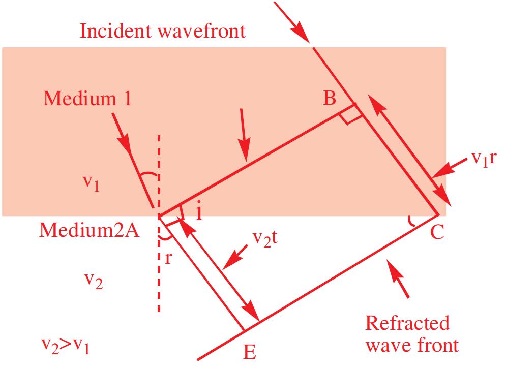
Reflection of a Plane Wave by a Plane Surface
We consider a plane wave AB incident at an angle i on a reflecting surface PQ. If v represents the speed of the wave in the medium and if τ represents the time taken by the wavefront to advance from the point B to C, then the distance BC = v τ . In order to construct the reflected wavefront we draw a sphere of radius v τ from the point ‘A’ as shown in figure. Let CE represent the tangent plane drawn from the point ‘C’ to this sphere. Obviously AE = BC = v τ and CE represents the reflected plane wavefront.
From triangle ABC, sin = BC i AC
From triangle AEC, sin() == AEBC rasAEBC ACAC
Hence, sin i = sin r. Therefore ∠=∠ir
This is the law of reflection.
Behaviour of a Lens, Prism, and Concave Mirror
It is interesting and useful to investigate the behaviour of lenses, prisms and spherical mirrors, when a plane wavefront is incident on them.
In the ∆ ABC, AB is perpendicular to A'A and AC is the perpendicular to AN. But we know that angles between two lines and their perpendicular are same.
So, the angle between AB and AC = Angle between A'A and AN = i
In the ∆ ABC
∠+∠+∠= AEC (90° – r) + 90° + ∠ C = 180°, so ∠ C = r
Behaviour of a prism: Consider a prism ABC of small angle and a plane wavefront PB incident on the prism [Fig] The lines LB and MP (normals to the incident wavefront PB) represent incident rays. It follows that the rays from different parts of the wavefront travel different thicknesses of the material of the prism. Light from point B travels totally inside the material of prism, while light from point P travels totally in air. The refracted wave front will be the locus of all those points to which light from different points on incident wavefront reaches in phase. Suppose that the light from point B reaches the corresponding point say C on refracted wavefront by travelling along path BC = x (say) inside the material of the prism and the light from point P reaches the corresponding point say Q on the refracted wavefront by travelling in air. Let the length of path between points P and Q i.e. PA + AQ be equal to y. As the time taken along the two paths should be same, or y xc yx vcv == , where cis velocity of light in air and v is velocity of light in the material of the prism. Since v is less than c, y is greater than x. Out of the total path y, light covers path PA. in air before it gets incident at point A and the remaining path AQ is covered after emerging from the prism. Hence, the emerging wavefront is CQ. The lines CL| and QM| (normal to the
emergent wavefront CQ) represent emergent rays. It explains why a ray of light passing through a prism is deviated towards the base of the prism.
Behaviour of a lens: Consider a plane wave front AB incident on a double convex lens. The rays of light from points A and B travel totally inside the air, while the ray of light from point ‘O’ travels partly in air and partly inside the material of thin lens. Again, the refracted wavefront will be the locus of all those points to which light from different points on incident wave front reaches in phase. As explained in case of behaviour of prism, it can be argued that the refracted wavefront will be a converging wavefront A’P2B’ [fig.], such that
Since distance OP is greater than AX or BY, consequently distance PO’ is less than XA’ or YB’. Therefore, the incident plane wavefront will be rendered into a converging spherical wavefront after reflection from the concave mirror as shown in the figure.
Key Insights:
■ The emerging wavefront has a depression at the centre and, therefore, the wavefront becomes spherical and converges to the point F, which is known as the focus.
10.1.8 The Doppler Effect
Doppler effect holds not only for sound (mechanical waves) but also for electromagnetic waves (non-mechanical waves) including microwaves, radio-waves and visible light. However, as electromagnetic waves do not require a medium for their propagation and the motion of source relative to detector or of detector relative to source represents same physical situation (as speed of light is independent of relative motion between source and observer), the formulae are different from that of sound.
Therefore, the wavefront after refraction through the lens is rendered into a converging wavefront as shown in the figure.
Behaviour of a spherical mirror: Consider a plane wavefront AB incident on a concave spherical mirror [Fig.] Just as discussed above, the refracted wavefront will be a converging wavefront in nature, such that
When any source emitting light (like sun, moon, star, atom etc.) is approaching or receding away from the observer (or) the distance between the source and the observer is increasing or decreasing then the frequency or wavelength of light appears to be changing to the observer. This apparent change in frequency or wavelength of light is called Doppler effect in light. Since the velocity of observer is negligible compared to speed of light, only the motion of source should be considered. So only two cases are possible, viz., of approach and recession.
Blue shift: When the distance between the source and the observer to decreasing (i.e. the source is approaching the observer) then the frequency of light appears to be increasing or wavelength appears to be decreasing, i.e., the spectral line in electro-magnetic spectrum gets displaced towards blue end, hence it is known as blue shift. The apparent frequency is
Ranging) systems for various applications. It is a device to determine the position and velocity of an aeroplane. The radar transmitter sends high frequency radio waves towards the plane moving with a velocity ‘vs’. The waves reflected by the plane are received by the receiver of radar station.
The apparent frequency ()
The apparent wavelength is
Red shift: When the distance between the light source and the observer is increasing (i.e. the source is receding away from the observer) the frequency of light appears to be decreasing or the wavelength of light appears to be increasing to the observer. Therefore the spectral line gets displaced towards red end, hence it is known as the red shift.
The apparent frequency is
The apparent wavelength is
Radar: The Doppler effect is extensively utilized in radar (Radio Detection and
By determining the difference of frequencies of transmitted and the reflected waves, the velocity of the plane is determined.
Key Insights:
■ The fractional change in frequency ∆ v / v is given by v radical / c , where v radical is the component of the source velocity along the line joining the observer to the source relative to the observer is considered positive when the source moves away from the observer. Thus, the Doppler shift can be expressed as ∆ =− νν ν radial c
■ The formula given above is valid only when the speed of the source is small compared to that of light.
■ A more accurate formula for the Doppler effect which is valid even when the speeds are close to that of light, requires the use of Einstein’s special theory of relativity.
■ The Doppler effect for light is very important in astronomy. It is the basis for the measurements of the radial velocities of distant galaxies.
Q. What speed should a galaxy move with respect to us so that the sodium line at 589.0 nm is observed at 589.6 nm?
Therefore, the galaxy is moving away from us with speed 306 km/s.
Try yourself:
A galaxy is emitting light at a wavelength of 5500Å. The galaxy is moving away from the earth with a velocity of 2 × 10⁶ m/s. What is the wavelength of light received on earth?
Ans: 5536.6Å
TEST YOURSELF
1. Light waves of wavelength λ propagate in a medium. If M and N are two points on the wave front and they are separated by a distance λ/4, the phase difference between them will be (in radian)
(1) π/2 (2) π/8 (3) π/4 (4) Zero
2. AB is incident wavefront on mirror R and mirror S whereas PQ and P’Q’ is reflected wavefront from mirror R and mirror S respectively. Choose the correct statement.
3. A plane waves is refracted according to Huygens’ principle from air to water, as shown below (where a, b, c, d, and e are the lengths on the figure). What will be the refractive index of water w.r.t. air?
(1) Mirror R is concave and mirror S is convex
(2) Mirror R is plane and mirror S is convex
(3) Mirror R is plane and mirror S is concave
(4) Mirror R is convex and mirror S is plane
(1) a/e (2) b/e
(3) b/d (4) d/b
Answer key
(1) 4 (2) 3 (3) 3
10.2 INTERFERENCE
When two or more coherent waves superimpose, the resultant intensity in the region of superposition is different from the intensity of individual waves.
The variation in intensity in the region of superposition of two or more waves of same frequency whose phase relationship does not change with time is known as interference.
Interference of waves occurs according to principle of superposition.
10.2.1 Coherent and Incoherent Waves
If two or more waves of the same frequency can maintain the same phase or constant phase difference over a distance and time, such waves are said to be coherent waves.
Two coherent waves may differ in amplitude but should have same frequency.
If one (or both) of the waves undergoes changes in frequency irregularly, the phase difference also changes irregularly then, the two waves are said to be incoherent.
Coherent Sources
Two sources which can emit light waves of the same wavelength with zero or a constant phase difference are called coherent sources.
The amplitude of light coming from coherent sources may (or) may not be equal.
Two independent sources of light, even though emitting same colour of light can not be coherent because the phase of the source of light varies rapidly and randomly.
A real source and its virtual image can act as coherent sources.
Two virtual images of a source of light can act as coherent sources.
Conditions for Constant Phase Difference
The phase difference between two superimposing waves may arise due to the following reasons.
1) The two waves may have started from the same point but may have different initial phases, ϕ1 and ϕ2
2) The two waves may have the same initial phase and have started from different points, and therefore may have to travel different distances before they come to the point of superposition. This difference between the distances travelled by the two waves before they superpose is referred to as path difference.
In order to have constant phase difference, let us consider two sources of light. The waves emitted by the sources are given by 11111 cos()=−+ωφyatKx 22222 cos()=−+ωφyatK x
The phase difference between the two waves is given by ()()() 12221112 tKxKx ∆=−+−+− φωωφφ ...(1)
The phase difference (Δϕ) will be constant i.e., will not vary with time, if the following conditions are satisfied.
i) 120Constant −==φφφ
i.e., the initial phase difference between the waves emitted by the sources does not vary with time.
ii) (ω1 – ω2)t = 0
As t ≠ 0, w 1 = ω2
i.e., n1 = n2 ⇒ λ1 = λ2 ⇒ K1 = K2 and Vn 2π
i.e., The waves should have same frequency and wavelength
So, from equation (1), 0 2() ∆=∆+ π φφ λ x …(2) where 012()=− φφφ
∴ From equation (2), it is clear that Δϕ is constant (or the two sources are coherent) if and only if they produce waves of same frequency (and hence same wavelength) and have a constant initial phase difference.
Key Insights:
■ As, in general, the emission of light from atoms is random and rapid and independent of each other, ϕ0 cannot remain constant with time and hence two independent light sources cannot be coherent.
■ Two independent laser sources emitting light waves of equal wavelengths can be coherent. Because they can maintain the constant phase difference for long time.
Methods of Obtaining Coherent Sources
It is possible for the two sources to have a definite and constant phase relation only when they both emit light coming from a single primary source. It is not possible from two separate sources.
Hence, effectively, two sources derived from a single source are known as coherent sources of light. Which are derived by two methods.
Division of Wavefront
The light wavefront emerging from a narrow slit is divided by passing it through two slits closely spaced side by side. The two parts of the same wavefront travel through different paths and reunite some where (on a screen) to produce fringe pattern. This is known as interference due to division of wavefront. This method is useful only with narrow sources as shown in the figure (a). It is done in Young’s double slit experiment, Lloyd’s mirror etc.
of any particle is equal to the vector sum of displacements produced by each of the waves.
If y1, y2,.........yn denote the displacements of ‘n’ waves of meeting at a point, then the resultant displacement is given by y = y 1 + y2 +...........+ yn
The term displacement (y) used here, is a general one. If we consider ripples on the surface of a liquid, the displacement means the actual displacement of the surface above or below its normal level. If the waves are electromagnetic, the displacement means the magnitude of the electric or magnetic field.
Superposition of Coherent Waves
Division of Amplitude
The amplitude (or intensity) of a light wave is divided into two parts namely reflected and transmitted components by partial reflection at a surface. The two parts, one wave reflected from top of a surface and other wave reflected from bottom of the surface travel through differeLnt paths and reunite to produce interference fringe pattern. This is known as interference due to division of amplitude. Interference in thin films employs this technique which is shown in the figure (b).Thus coherent sources can be obtained either by the division of wavefront or by the division of amplitude.
10.2.2 Principle of Superposition of Waves
If two or more waves meet at a place simultaneously in the same medium, the particles of the medium undergo displacements due to all the waves simultaneously. The resultant wave is due to the resultant displacement of the particles.
Principle of superposition of waves states that when two or more waves are simultaneously impressed on the particles of the medium, the resultant displacement
Consider two waves y 1 and y 2 travelling in space with an angular frequency ω. Let the two waves arrive at some point O simultaneously. Let y1 and y2 represent the displacements of the two waves at this point O.
()111 cos ∴=+ωφyAt and ()222 cos =+ωφyAt
Then, according to the principle of superposition, the resultant displacement at the point O is given by y = y 1 + y2 or ()() 1122 coscos =+++ ωφωφyAtAt
111 (coscossinsin)=ω−ωφφAtt 222 (coscossinsin)+ω−ωφφAtt (cos)cos(sin)sin =-φωφω AtAt
cos()=ω+ φ At where 1122coscoscos =+ φφφAAA ...(1) and 1122sinsinsin =+ φφφAAA ...(2)
Here, A and ϕ are, respectively, the amplitude and initial phase of the resultant displacement at O.
Squaring and adding equations (1) and (2), we get
22 121212 2cos =++−φφ AAAAA 22 12122cos =++φ AAAA ….(3)
where 12 =− φφφ , phase difference between the two waves.
Dividing equation (2) by equation (1), we get 1122 1122 sinsin tan coscos + = + φφφ φφ AA AA ....(4)
Since the intensity of a wave is proportional to square of the amplitude, the resultant intensity I of the wave from equation (3) may be written as
12122cos =++φ IIIII ...(5)
where I 1 and I 2 be the intensities of the two waves.
It can be seen that the amplitude (intensity) of the resultant displacement varies with phase difference of the constituent displacements.
Case 1: When 120,2,4.......=−= φφφππ
cos1⇒= φ 12∴=+AAA from (3) and 12=+ III from (5)
Hence, the resultant amplitude is the sum of the two individual amplitudes. This condition refers to the constructive interference.
Case 2: When 12,3,5..........=−= φφφπππ
cos1⇒=− φ
12∴=−AAA and 12 =− III
Hence, the resultant amplitude is the difference of the individual amplitudes and is referred to as destructive interference.
Superposition of Incoherent Waves
Incoherent waves are the waves which do not maintain a constant phase difference. The phase of the waves fluctuates irregularly with time and independently of each other. In case of light waves the phase fluctuates randomly at a rate of about 108 per second. Light detectors such as human eye, photographic film etc, cannot respond to such rapid changes. The detected intensity is always the average intensity, averaged over a time interval which is very much larger than the time of fluctuations. Thus, 12122cos =++<> φ av IIIII . The average value of the cos ϕ over a large time interval will be zero and, hence, 12=+ av III
This implies that the superposition of incoherent waves gives uniform illumination at every point and is simply equal to the sum of the intensities of the component waves.
10.2.3 Relation between Path Difference and Phase Difference
i) The difference in the paths traversed by the two interfering light waves at the time of arrival at the point of superposition is called path difference (Δx)
ii) The difference in the phase angles expressed in radians between the two interfering waves at the time of arrival at the point of superposition is called phase difference (ϕ)
We know that if a wave covers a distance of one wavelength, it differs in phase by 2π radians. If the wave travels a distance x, its phase changes by 2 x=∆φπ λ
Key Insights:
■ If a wave travels a distance d in a medium of refractive index μ, as its optical path is μd, its phase changes by, () 2 = π φµ λ d
Q. Two coherent sources emit light of intensities I and 4I at wavelength λ. The wave arrive at some point P simultaneously. If the path difference between the waves is λ/4, find the resultant intensity at P.
Sol. Phase difference 2 . 42 =×= φπλπ λ 2 424cos5 2 =++= π R IIIII
Try yourself:
Two coherent wave of intensity I and 9I arrive at some point O simultaneously. Find the maximum possible resultant intensity at point O.
Ans: 16I
10.2.4 Types of Interference
Constructive interference: At some points in the superposition region, the waves superpose in such a way that the resulting intensity is greater than the sum of the intensities due to individual waves. This is called constructive interference.
Condition: The resultant intensity will be maximum when the two waves reach the point in phase, i.e., the crest of 1st wave exactly falls on crest of 2nd wave and the trough of 1st wave falls on trough of 2nd wave. Then, the waves are said to undergo constructive interference.
Destructive Interference: At some other points in the superposition region, the waves superpose in such a way that the resultant intensity is lesser than the sum of the individual intensities. This is called destructive interference.
Condition: The resultant intensity will be minimum when the two waves reach the point with phase difference of π radians or 180°, i.e., crest of the 1st wave exactly falls on the trough of the 2nd wave. Then, the waves are said to undergo destructive interference.
10.2.5 Young’s Double Slit Experiment
Thomas Young gave the first demonstration of the interference of light waves. Young admitted the sunlight through a single pin hole and then directed the emerging light on to two pin holes. Finally, the light coming from the two pin holes was received on the screen. The spherical wavefronts emerging from the pin holes interfered with each other and a few coloured fringes were observed on the screen. These fringes were faint and difficult to observe. To remove this difficulty the pin holes were later replaced with narrow slits that collect a much more light and the sun light was replaced by monochromatic light. Young’s experiment is known as double-slit experiment.
Diffracted beam of S1
monochromaticlight
Diffracted beam of S2
S1 S2 S Interference region T D d
Fig (a)
The figure (a) shows a simple arrangement of double slit experiment. ‘S’ is a monochromatic source. Light from ‘S’ is incident on two closely spaced slits S1 and S2. Their apertures are nearly equal to wavelength of incident light. This is to get diffracted beam from the slits. The slits are rectangular in shape with their lengths normal to the plane of the paper and they are at equal distances from S. The two slits S1 and S2 emit cylindrical coherent waves with zero initial phase difference (i.e., ϕ = 0). Light waves from the slits spread out (due to diffraction) as shown in the figure (b) and fall on the screen T which is at
distance D. The distance of screen D is very large compared to the distance of separation ‘d’ between the two slits, i.e., D >> d.
Due to superposition of wavefronts in common diffracted region, an interference pattern of alternate bright (maxima) and dark (minima) bands or fringes are observed on the screen T.
the experiment is carried out in air. Therefore the optical paths are identical with geometrical paths. The nature of interference of the waves at P depends simply on how many waves are contained in the length of the path difference S 2 N. If S 2 N contains an integral number of wavelengths, the two waves interfere constructively, producing maximum intensity of light on the screen at P. If it contains an odd number of half wavelengths, then the waves interfere destructively and produce a minimum intensity at P.
Since D >> d and D >> y, therefore, the angular position θ of the point ‘P’ w.r.t centre of the separation between the slits is given by sintan≈=θθ y D
The path and hence phase difference produced between the two waves arriving at the point ‘P’ is due to the difference in path length covered by each wave. Thus the path difference at ‘P’ is given by 212sin ∆=−==≈
Expressions of path difference:
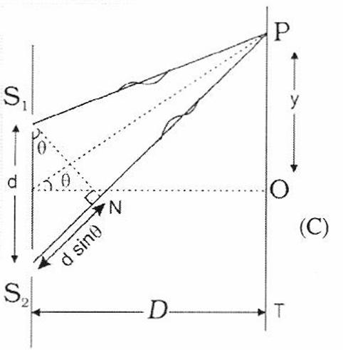
Let us obtain a general expression for the path difference between the two waves on arriving at a point.
Consider a point ‘P’ on the screen at a distance ‘y’ from the centre O of the screen as shown in figure (c)
The waves emitted from the slits S 1 and S2 are initially in phase with each other. The difference in the path lengths of these two waves is S2N on reaching P. We assume that
D ….(1) and phase difference 2 =∆x φπ λ ,
Expression for Intensity of Interference Pattern
Suppose the equations for the waves reaching at point P coming from S 1 and S 2 are given by y1 = A cos ωt and y2 = A cos (ωt + ϕ)
According to principle of superposition, the resultant displacement at P is given by y = y1 + y2 = A cos ωt + A cos (ωt + ϕ) or y = A cos ωt + A cos ωt cos ϕ – A sin ωt sin ϕ (or) y = A (1 + cosϕ ) cos ωt – A sin ϕ sin ωt ……. (2)
Suppose A (1 + cosϕ) = R cos α ……. (3) and A sin ϕ = R sin α …….(4) then equation (2) becomes y = R cos α cos ωt – R sin α sin ωt or y = R cos (ωt + α)
This equation clearly shows that superposition of two waves from slits S 1 and S 2 at P yields a similar wave with resultant displacement y, resultant amplitude R and resultant phase α.
We know that the intensity of a wave is proportional to the square of the amplitude, for individual wave, I 0 = KA2 and for resultant wave, I = KR 2 (Here K is a proportionality constant)
From equations (3) and (4)
R2 = R2 cos2 α + R2 sin2 α = A2 (1 + cos ϕ) 2 + A2 sin2ϕ = A2 [1 + cos2 ϕ + 2 cos ϕ + sin2 ϕ] = A2 [ 2 + 2 cos ϕ]
AA
222 21cos22cos 2 =+=
2224cos2cos 22 ∴=⇒=φφRARA
or 222 4cos 2 = φ KRKA
or 2 0 4cos 2 = φ II …….(6)
Thus, we observe that the resultant intensity at P depends on the value of phase difference which in turn depends on the path difference ϕ.
For a given point on the screen, path difference is Δx and, hence, phase difference ϕ remains constant in case of coherent sources. Therefore, for a given point on the screen, the intensity remains constant and from point to point, its value changes. Thus, we get a fringe pattern on the screen with alternate bright and dark fringes.
Q. In an arrangement of double slit experiment, the slits are illuminated by light of wavelength 600 nm. The distance of the first point on the screen from the central maximum where intensity is 75% of central maximum is
* * S1 S2
0.25cm 120cm
Screen
Sol. I max = I1= 4a2 (at central maximum)
I2 = 75% of I1 (at point P)
322 3 43 44 ==×= I aa
∴ Resultant amplitude at ‘P’ is 3 = Aa
If ϕ is phase difference 222 12122cos =++φAAAAA
322222cos =++φaAAA : 3 = φπ
Then corresponding path difference
2 6 πλφ⇒ λ == x x
∴ Path difference = d xyD
y = 4.8 × 10⁻⁵ m
Try yourself:
In Young’s double slit experiment intensity at a point is (1/4) of the maximum intensity. Angular position of these points is
Ans: 1sin 3
Bright Fringes
Bright fringes occur wherever the waves from S1 and S2 interfere constructively. i.e. on reaching ‘P’, the waves with crest (or trough) superimpose at the same time and they are said to be in phase.
In general, constructive interference occurs if S 1P and S 2P differ in path by an integral multiple of λ
Thus the condition for finding a bright fringe at ‘P’ is that S 2P – S1P = nλ, where n = 0, ±1, ±2, ±3, ……. and n is called
the order of bright fringe. Hence for nth order bright fringe, the path difference is d sin θ = nλ (from equation (1))
λ n y dn D ∴= λ n nD yd
Where yn is the position of nth maximum from O.
The bright fringe corresponding to n = 0, is called the zero-order fringe or central maximum.
The bright fringe corresponding to n = 1 is called first order bright fringe
φ II
The intensity 2 0 4cos 2
=
For maximum intensity cos1 2 = φ ..0,,2......... 2 φ=±±ππ ie
(or) Phase difference between the waves
ϕ=±2πn with n = 0, 1, 2, 3 ……
The corresponding path difference Δx = nλ, Hence I max = 4I 0
Dark Fringes
Dark fringes occur wherever the waves from S1 and S2 interfere destructively, i.e., on reaching ‘P’, one wave with its crest and another wave with its trough superimpose. Then, the phase difference between the waves is π and the waves are said to be in opposite phases.
Destructive interference occurs at P, if S 1P and S2P differ by a odd integral multiple of 2 λ .
Thus, the condition for finding dark fringe at P is that S2P – S1P = (2n – 1) 2 λ
Where n = ± 1, ± 2, ± 3, …….., and n is called order of dark fringe. Hence for nth order dark fringe, the path difference,
sin(21)(21) 22 =−⇒=−
where yn is the position of nth minima from O.
Q. A beam of light consisting of two wavelengths 6500 Å and 5200 Å is used to obtain interference fringes in a Young’s double slit experiment.
i) Find the distance of the third bright fringe on the screen from the central maximum for wavelength 6500 Å
ii) What is the least distance from the central maximum where the bright fringes due to both the wavelengths coincide? Distance between the slits is 2 mm, distance between the slits and the screen L = 120 cm.
Sol. i) The distance of the mth bright fringe from the central maximum 3 3 ; == λλ m mLL yydd () 10 3 36500101.20 1.17 210 ××× == × mm
ii) Let the n th bright fringe of wavelength λ m coincide at a distance y from the central maximum then == λλ mn mLnL ydd
65005 52004 ∴=== λ λ n m m n
i.e., 5th bright fringe of wavelength 5200Å coincides with the 4th bright fringe of wavelength 6500Å
∴= λ m m mL yd
() 10 3 55200101.20 1.56 210 ×× == × mm
Q. In YDSE bichromatic light of wavelengths 400 nm and 560 nm are used. The distance between the slits is 0.1 mm and the distance between the plane of the slits and the screen is 1 m. What is the minimum distance between two successive regions of complete darkness?
Sol. Let nth minima of 400 nm coincides with mth minima of 560 nm. Then, ()()400560 2121 22
nm
or 21714 21510 === n m
i,e., 4 th minima of 400 nm coincides with 3 rd minima of 560 nm. Location of this minima is,
9
1 241100040010 14 20.1 ×−× == × Ymm
Next 11th minima of 400 nm will coincide with 8th minima of 560 nm.
Location of this minima is, 9
2 (2111)(1000)(40010)42 20.1 ×−× == × Ymm
∴ Required distance Y2 – Y1 = 28 mm.
Try yourself:
Two coherent sources are 0.18 mm apart and the fringes are observed on a screen 80cm away. It is found that with a certain monochromatic source of light, the fourth bright fringe is situated at a distance of 10.8 mm from the central fringe. Calculate the wavelength of light.
Ans: 6075Å
Key Insights:
■ The first dark fringe occurs when S2P – S1P = 2 λ
This is called first order dark (n = 1) fringe and similarly, for S2P – S1P = 3 2 λ , second order dark fringe (n = 2) occurs, and so on.
The intensity, 2 0 4cos 2 = φ II
For minimum intensity, cos0 2 = φ
i.e., 35 ,,........ 2222 =±±± φπππ
(or) ,3,5........=±±± φπππ
(or) (21)=±− φπ n with n = 1, 2, 3
The corresponding path difference, () 21 2 ∆=− λ xn , hence, Imin = O
■ Constructive interference is at a point Q if the path difference is 2λ.
S1
S2 S1 Q = 7λ Q
S2Q-S1Q=2λ S2Q=9λ
■ Destructive interference is at a point R if the path difference is 2.5λ.
S1
S2
S2 R = 7.25λ R S 1 R=9.75λ
S1R-S2R= 2.5λ
■ If I1 and I2 are the intensities and A1 and A2 are the amplitudes of individual waves, then 12122cos =++φ IIIII
For dark fringes, ()21cos1 =±−⇒=− φπφ n min1212 2 ∴=+−IIIII ()2 2 min1212()=−∝− ieIIIAA
Thus, at minima, the resultant intensity is lesser than the sum of two intensities (I1 + I2), by an amount 212 II
■ In case of two coherent sources of different intensities and different amplitudes with a phase difference ϕ , refer following table. 1
(if I1 = I2 = I0)
■ The intensity at maxima is larger than the sum of individual intensities (I 1 + I 2) by an amount 212 II while at minima, the intensity is smaller by an amount 212 II as shown in figure. So, in interference, energy is neither created nor destroyed but redistributed i.e. conservation of energy holds good in the phenomenon of interference.
■ Average intensity of the bands for coherent and incoherent sources is same and is given by maxmin0 0 40 2 22 ++ === ave III II
Q. In the Young’s double slit experiment apparatus shown in figure, the ratio of maximum to minimum intensity on the screen is 9. If the wavelength of light used is λ , then find the value of y
ax in I II or 1 3 1 + = x x where 1 2 = I x I ∴ x = 2 ∴ 1 2 4 = I I , I1 = 4I2 i.e., if I2 = I0, then I1 = 4I 0 2 00 2 4cos 23 =∴=φπ φ II
33
Try yourself:
In YDSE, the interfering waves have amplitude in the ratio 3 : 2. Find the ratio of (a) Amplitude and (b) Intensities between the bright and dark fringes. Ans: (a) 5 (b) 25
Fringe Width (β)
The distance between two adjacent bright (or dark) fringes is called the fringe width. It is denoted by β. The nth order bright fringe
occurs from the central maximum at = λ n nD y d .
The ( n + 1) th order bright fringe occurs from the central maximum at 1 (1) + + = λ n nD yd .
∴ The fringe separation, β is given by 1+ =−= βλ nn D yyd
In a similar way, the same result will be obtained for dark fringes also.
∴ Fringe width, = βλD d
Thus, fringe width is same everywhere on the screen and the width of bright fringe is equal to the width of dark fringe.
∴===βββλ brightdark D d
Fringe width β is (i) directly proportional to the wavelength λ (ii) directly proportional to the slit-screen distance D (iii) inversely proportional to the separation of the slits ‘d’. In interference, maxima and minima are alternate and equally spaced as path difference between two consecutive maxima or minima is λ.
Key Insights:
i) The fringe width β is independent of the order of the fringe, as long as d and θ are small.
ii) Since ,Re , ∝>> βλββλλ Redvoiletdvoilet as
iii) In YDSE, if blue light is used instead of red light, then β decreases () < λλ BR
iv) If YDSE apparatus is immersed in a liquid of refractive index μ, then wavelength of light
v) If YDSE is conducted in vacuum instead of air, then β increases () > λλ vaccumair
vi) In certain field of view on the screen, if n 1 fringes are formed when light of
wavelength λ1 is used and n 2 fringes are formed when light of wavelength is λ 2 used, then
constantconstant==⇒= λλnD yn d 1122
∴=λλnn (or) 1122 = ββnn
vii) The distance of n th bright fringe from central maximum is ()==λβ nbri nD yn d
The distance of mth dark fringe from central maximum is
mdark mm D yd
∴ The distance between nth bright and mth dark fringes is ()()() 21 2 −=−ββ nmbridark m yyn
viii) When white light is used in YDSE, the interference patterns due to different component colours of white light overlap (incoherently). The central bright fringes for different colours are at the same position. Therefore, the central fringe is white. The fringe closest on either side of the central white fringe is red and the farthest will appear blue. After a few fringes, no clear fringe pattern is seen.
ix) At constant temperature, with increase in pressure, the refractive index of the medium increases and hence, fringe width decreases. 1 , ∝∝↑↑∴↓ µβ PdensityAsd V
x) If one of the slits is closed, diffraction bands are observed instead of interference.
xi) The linear position ‘y’ is related to the angular position θ by, tan ≈≈θθ y D and angular fringe width ∆ ∆=== θβλ y DDd
In a medium of refractive index μ, ∆ ∆= θ θ µ air m
xii) If the screen is placed parallel to plane of slits, the path difference between the waves at P is Δx=dsinθ. This path difference increases as θ increases. Hence the order of the fringe increases as we move away from O on the screen.
n = 2, Second bright
n = 2, Second dark
n = 1, First bright
n = 1, First dark
n = 0, Central bright
n = 1, First dark
n = 1, First bright
n = 2, Second dark
n = 2, Second bright
With point sources (pin holes), the type of fringes on the screen are hyperbolic with straight central bright fringe and with cylindrical sources, the fringes are straight.
xiii) In order to determine the shape of the interference pattern on the screen, we note that a particular fringe would correspond to the locus of points with a constant value of S2P – S1P. Now, the locus of the point P lying in the x – y plane such that S 2P –S 1P (= Δx ) is a constant, is a hyperbola. Thus, the fringe pattern will strictly be a hyperbola; however, if the distance D is
very large compared to the fringe width, the fringes will be very nearly straight lines ,as shown in figure.
xiv) If the screen is placed perpendicular to plane of the slits, the path difference between the waves at P is Δx = d cos θ (see figure). This path difference decreases as θ increases. Hence, the order of the fringe decreases as we move away from O on the screen.
n4 = n5 = n6 = n7 = n8
With point sources, the type of fringes on the screen are concentric circular fringes and with cylindrical sources, fringes are straight. In this situation, if S1S2 = nλ, the central fringe is bright and if 12(21), 2 =− λ SSn the central fringe is dark.
xv) The number of fringes obtained on screen depends on the amount of diffraction occurring at the slits and this in turn depends on their width. The narrower the slits, the greater will be the number of fringes due to increased diffraction but the fainter they will be, since less light gets through. In general, the slits have to be many wavelength wide so that we get easily observable fringes.
xvi) To know maximum number of possible maxima on the screen
d sin θ (or) sin = θλ n d
As sin1,1 ≤≤θλ n d ∴≤ λ d n
Therefore, the maximum number of complete maxima on the screen will be 2[n] + 1.
Example:
If d = 3λ then sin 33 ==θλ λ nn As sin1, ≤ θ
n can take values -3, –2, –1, 0, 1, 2, 3
∴ Maximum number of maxima is 7.
xvii) Fringe visibility (or) band visibility (V): It is the measure of contrast between the bright and dark fringes
Fringe visibility, maxmin maxmin = + II V II where max1212 2 =++ IIIII and min1212 2 =+− IIIII
V has no unit and no dimensional formula.
Generally, 0 < V < 1.
Fringe visibility is maximum, if I min = 0, then V=1.
For poor visibility, I max = Imin, then V= 0.
i.e., if V = 1, then the fringes are very clear and contrast is maximum and if V = 0, then there will be no fringes and there will be uniform illumination i.e., the contrast is poor.
xviii) When one slit is fully open and another one is partially open then the contrast between the fringes decreases.
i.e., if the slit widths are unequal, the minima will not be completely dark.
xix) Missing wavelengths in front of one slit in YDSE:
Suppose, P is a point of observation in front of slit S 1, as shown in figure. Path difference between the two waves from S1 and S2 is 22 21 ∆=−=+− xSPSPDdD
x D …(1)
But for missing wavelengths, intensity will be zero, i.e., the corresponding path difference, () 21 2 ∆=− λ xn …(2)
From equations (1) and (2), () 2 21 22 =− λ d n D ∴ Missing wavelength, () 2 21 = λ d nD
By putting n=1, 2, 3,...., the miss ing wavelengths at P are 222 ,,,....... 35 = λ ddd DDD
In the above case, if bright fringes are to be formed exactly opposite to S 1, then 22 22 =⇒= λλ dd n DDn
By putting n = 1, 2, 3,...., the possible wavelengths at P are 222 ,,,.... 246 = λ ddd DDD
Lateral Displacement of Fringes
To determine the thickness of a given thin sheet of transparent material such as glass or mica, that transparent sheet is introduced in the path of one of the two interfering beams. The fringe pattern gets displaced towards the beam in whose path the sheet is introduced. This shift is known as lateral displacement or lateral shift.
(1) ∴−= µ tdy D
∴ Lateral shift ()()(1)1 =−=− β µµ λ D ytt d
(or) Thickness of sheet ()(1)1 == λ µµβ tydy D
a) From the above it is clear that For a given colour, shift is independent of order of the fringe i.e. shift in zero order maximum = shift in 9 th minima (or) shift in 6 th maxima = shift in 2 nd minima. Since the refractive index depends on wavelength hence lateral shift is different for different colours.
Suppose S 1 and S 2 are the coherent monochromatic sources. The point O is equidistant from S1 and S2, where we obtain central bright fringe. Therefore, the optical path S 1O = S 2O. Let a transparent sheet of thickness ‘t’ and refractive index ‘ μ ’ be introduced in one of the beams as shown in the figure. The optical path lengths S 1O and S2O are now not equal and central bright fringe shifts to P from O. The light waves from S1 to P travel partly in air and partly in sheet. The distance travelled in air is (S1P – t) and that in the sheet is ‘μt’. The optical path from S1 to P = (S1P – t) + μt.The optical path from S 2 to P = S2P.
To get central zero fringe at P
12⇒−+= µ SPttSP
21(1)∴−=− µ SPSPt
Since μ > 1 , this implies S2P > S1P; hence, the fringe pattern must shift towards the beam from S1.
But 21sin−=≈ θ SPSPddy D , where ‘y’ is the lateral shift.
b) The number of fringes shifted = lateralshift fringewidth ()(1)()1 ∴===− µλµβλ yt nornt Therefore, number of fringes shifted is more for shorter wavelength.
c) If a transparent sheet of thickness ‘t’ and its relative refractive index μr (w.r.t surroundings) be introduced in one of the beam of interference, then
1) the lateral shift (1) = µr tD yd
2) the number of fringes shifted (1) = µ λ r t n
d) Due to the presence of transparent sheet, the phase difference between the interfering waves at a given point is given by 2(1)=− π λµ t
e) A YDSE is performed with two different colours of light of wavelengths λ 1 and λ 2.On placing the same transparent sheet
in the path of one of the interfering waves it is observed that the central bright fringe shifts to original n1th and n2th order bright fringe then n1λ 1 = n2λ 2.
f) When two different transparent sheets of thickness t 1 , t 2 and refractive index µ 1 , µ 2 are placed in the paths of two interfering waves in YDSE, if the central bright fringe position is not shifted, then
1122 (1)(1) −=−µµtt
Q. In a Young’s double slit experiment, the fringes are displaced by a distance x when a glass plate of refractive index 1.5 is introduced in the path of one of the beams. When this plate is replaced by another plate of same thickness, the shift of fringes is (3/2)x. The refractive index of second plate is
Sol. (1)(1.51) =⇒= µ ShifttDtD x dd …(i) and 3(1) 2 = µ tD x d …(ii)
Dividing Eq.(i) by Eq.(ii)
20.5 1.75
31 =⇒= µ µ
Try yourself:
A plate of thickness t made of a material of refractive index μ is placed in front of one of the slits in a double slit experiment. What should be the minimum thickness t which will make the intensity at the centre of the fringe pattern zero?
Ans: )(21 = λ µ t
Conditions for Observing Sustained Interference with Good Contrast
1. The initial phase difference between the interfering waves must remain constant. Otherwise the interference will not be sustained, i.e., the sources must be coherent.
2. The frequencies and wavelengths of the two waves should be equal. (If not, the phase difference will not remain constant and so the interference will not be sustained)
3. The light must be monochromatic. (This eliminates the overlapping of patterns as each wavelength corresponds to one interference pattern)
4. The amplitudes of the interfering waves must be equal (This improves contrast with I max = 4I 0 and Imin = 0)
5. The sources must be close to each other. (Otherwise due to small fringe width, fringes may be so close to each other that eye cannot resolve them resulting in uniform illumination)
6. The sources must be narrow (A broad source will be equal to a large number of narrow sources and each set of two sources will give its own pattern and overlapping of patterns will result in uniform illumination)
7. If the interfering beams are polarised, they must be in the same state of polarisation otherwise instead of interference, unpolarised light will result.
Applications of Interference
1) It is used to determine refractive index of liquids or gases.
2) Thickness of transparent thin sheets can be determined
3) Reflectivity of the surfaces of lenses or prisms can be tested.
4) It is used to determine the wavelength of light λ with an accuracy up to eight significant digits.
5) It is used in holography to produce threedimensional images.
6) Quality of the surface polish can be checked.
7) It is used to know the difference between the wavelengths of two closely spaced spectral lines.
10.2.6 Interference in Thin Films:
A thin film is a thin sheet of transparent material such as glass, mica or thin surface of a soap bubble and its thickness about order of one wavelength in the visible region.
When the light is incident on a parallel thin film of refractive index µ and thickness ‘t’, a small portion of it gets reflected from the top surface and a major portion is transmitted in to the film. Again a small part of the transmitted component is reflected back into the film by the bottom surface and the rest of it transmitted from the lower surface of the film. The second reflected wave transmits major component light at the upper surface. These two rays derived from the same incident ray but appear to come from two sources located below the film. The reflected waves 1 and 2 travel along parallel paths and they made to converge with lens to get interference.
If ‘r’ is the angle of incidence of light in the film (medium), the optical path difference between two reflected rays = 2µt cos r. The proof is beyond our syllabus.
a) When one of the rays is reflected at the boundary of rarer to denser medium, as shown in figure (a) a path change of 2 λ occurs.
Hence, true path difference = 2cos 2 λ µtr
For maxima, 2cos 2 −= λ µλ trn
2cos(21), 2 =+ λ µtrn where n = 0, 1, 2, 3...
similarly for minima
2cos(21) 22 −=− λλ µtrn
2cos = µλ trn , where n = 1, 2, 3, …
For nearly normal incidence r ≈ 0.
2(21) 2 =+ λ µtn (For maxima)
2 = µλ tn (For minima)
b) When both reflected rays are reflected from denser to rarer boundary (or) rarer to denser boundary, phase change between them is zero as shown in figure (b).
Hence, true path difference = 2cos µtr
For maxima, 2cos = µλ trn , where n = 0, 1, 2, 3, …
For minima, 2cos(21) 2 =− λ µtrn , where n=1, 2, 3, …
For nearly normal incidence r ≈ 0, 2µt = nλ, (For maxima)
2(21) 2 =− λ µtn , (For minima)
Q. A parallel beam of light of intensity Io is incident an a glass plate, 25% of light is reflected by upper surface and 50% of light is reflected by lower surface. The ratio of maximum to minimum intensity in interference region of reflected rays is (Assume that light reflected from lower surface l refracts from upper surface entirely)
Sol. 1 25 1004 × == I II
The intensity of transmitted light is
TEST YOURSELF
The intensity of light reflected for lower surface is
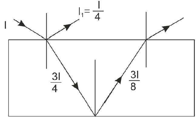
Try yourself:
In the figures, PO and QB are the extreme rays of a wavefront AB of monochromatic light of wavelength λ. Find the value of angle θ, for which the ray QB and ray OB interfere constructively.
1. The displacements of two interfering light waves are y1 = 4sinωt and y2 = 3cosωt. The amplitude of the resultant wave is (y1 and y2 are in CGS system)
(1) 5 cm (2) 7 cm
(3) 1 cm (4) Zero
2. Two light waves are represented by ya t 1 = sin and y2 = a sin(ωt+ δ). When they overlap, the phase angle of the resultant wave is
(1) 2δ
(2) δ/3
(3) δ/4
(4) δ/2
3. When two coherent monochromatic light beams of intensities I and 4 I are superimposed, the ratio between maximum and minimum intensities in the resultant beam is
(1) 9 : 1
(2) 1 : 9
(3) 4 : 1
(4) 1 : 4
4. Four light sources produce the following waves
(i) y1 = a sin(ωt + f 1)
(ii) y2 = a sin(2ωt)
(iii) y3 = a sin(ωt + f 2)
(iv) y4 = a sin(3ωt + f )
Superposition of which two waves gives rise to interference?
(1) (i) and (ii) (2) (ii) and (iii)
(3) (i) and (iii) (4) (iii) and (iv)
5. A screen is at a distance of 2 m from narrow slits that are illuminated with light of 589 nm. The 10th minimum lies at 0.005 m on either side of the central maximum, then the distance between the slits will be
(1) 0.024 mm (2) 2.23 mm
(3) 2.4 mm (4) 24 mm
6. In Young’s double slit experiment with a monochromatic light of wavelength 4000 Å, fringe width is found to be 0.4 mm. When the slits are now illuminated with a light of wavelength 5000 Å, the fringe width will be
(1) 0.32 mm (2) 0.5 mm
(3) 0.6 mm (4) 0.8 mm
7. In Young’s double slit interference experiment the wavelength of light used is 6000 Å. If the path difference between waves reaching a point P on the screen is 1.5 microns, then at that point P,
(1) Second bright band occurs
(2) Second dark band occurs
(3) Third dark band occurs
(4) Third bright band occurs
8. The intensity of central fringe in the interference pattern produced by two identical slits is I. When one of the slits is closed the intensity at the same point is I 0 The relation between I and I 0 is
(1) I = 4I 0 (2) I = 2I 0
(3) I = 4I 0 (4) 0 2 I I =
9. In the case of interference, the maximum and minimum intensities are in the ratio 16 : 9. Then,
(1) the maximum and minimum amplitudes will be in the ratio 9 : 5
(2) the intensities of the individual waves will be in the ratio 4 : 3
(3) the amplitudes of the individual waves will be in the ratio 7 : 1
(4) the amplitudes of the individual waves will be in the ratio 4 : 1
10. In double slit experiment, the distance between two slits is 0.6 mm and these are illuminated with light of wavelength 4800 Å. The angular width of dark fringe on the screen at a distance 120 cm from slits will be
(1) 8 × 10⁻⁴ radian
(2) 6 × 10⁻⁴ radian
(3) 4 × 10⁻⁴ radian
(4) 16 × 10–4 radian
11. In Young’s double slit experiment, bluegreen light of wavelength 500 nm is used. The slits are 1.20 mm apart, and the viewing screen is 5.40 m away from the slits. What is the fringe width?
(1) 6.2 mm
(2) 4.2 mm
(3) 2.25 mm
(4) 1.25 mm
12. A double slit experiment is performed with light of wavelength 500 nm. A thin film of thickness 2 µm and refractive index 1.5 is introduced in the path of the upper beam. The location of the central maximum will (1) remain unshifted
(2) shift downward by nearly two fringes (3) shift upward by nearly two fringes
(4) shift downward by 10 fringes
13. When a mica plate of thickness 0.1 mm is introduced in one of the interfering beams, the central fringe is displaced by a distance equal to 10 fringes. If the wavelength of the light is 6000 Å, the refractive index of the mica is (1) 1.06 (2) 1.6
(3) 2.4 (4) 1.2
14. The maximum number of possible interference maxima for slit separation equal to twice the wavelength in Young’s double slit experiment is (1) infinite (2) five
(3) three (4) zero
15. An electromagnetic wave emitted by source travels 21 km to arrive at a receiver. The wave while travelling in another path is reflected from a surface at 19 km away and further travels 12 km to reach the same receiver. If destructive interference occurs at the receiving end, the maximum wavelength of the wave is
(1) 0.5 km
(2) 1 km
(3) 5 km
(4) 10 km
16. In Young’s double slit experiment, the 10 th maximum of wavelength λ 1 is at a distance of y 1 from the central maximum. When the wavelength of the source is changed to λ2, 5th maximum is at a distance of y2 from its central maximum. The ratio 1 2 y y
is
17 The path difference between two interfering waves at a point on the screen is λ/6 from central maximum. The ratio of intensity at this point and that at the central fringe will be
(1) 0.75 (2) 7.5 (3) 85.3 (4) 853
18. In Young’s double slit experiment with monochromatic source of light of wavelength 6000 Å, if the path difference at a point on the screen is 6×10⁻⁶ m, the number of the bright band formed at that point is (1) 2 (2) 4 (3) 6 (4) 10
19. A mixture of light, consisting of wavelength 590 nm and an unknown wavelength, illuminates Young’s double slit and gives rise to two overlapping interference patterns on the screen. The central maximum of both lights coincide. Further, it is observed that the third bright fringe of known light coincides with the 4 th bright fringe of the unknown light. From this data, the wavelength of the unknown light is (1) 885.0 nm (2) 442.5 nm (3) 776.8 nm (4) 393.4 nm
20. Young’s double slit experiment is first performed in air and then in a medium other than air. It is found that 8th bright fringe in the medium lies where 5th dark fringe lies in air. The refractive index of the medium is nearly
(1) 1.78 (2) 1.25
(3) 1.59 (4) 1.69
21. In a double slit experiment, when light of wavelength 400 nm was used, the angular width of the first minima formed on a screen placed 1 m away, was found to be 0.2°. What will be the angular width of the first minima, if the entire experimental apparatus is immersed in water?
(1) 0.05° (2) 0.1°
(3) 0.266° (4) 0.15°
Answer key
(1) 1 (2) 4 (3) 1 (4) 3
(5) 2 (6) 2 (7) 3 (8) 1
(9) 3 (10) 1 (11) 2 (12) 3
(13) 1 (14) 2 (15) 4 (16) 1
(17) 1 (18) 4 (19) 2 (20) 1 (21) 4
10.3 DIFFRACTION
According to rectilinear propagation of light, if an opaque obstacle or aperture is placed between the source of light and a screen a sharp shadow or an illuminated region is obtained on the screen as shown in figures (a) and (b).
In the 17th century, Grimaldi discovered that, if the size of obstacle or aperture is comparable with the wavelength of light, the light deviates from rectilinear propagation near the edges of obstacle or aperture. This property of bending of waves around the edges of a small obstacle or aperture is called diffraction. As a result of diffraction, when light passes through a small aperture or opaque obstacle, it spreads to some extent into the region of the geometrical shadow also. Hence, due to encroachment of light, the edges of the shadow (or illuminated region) do not remain well defined and sharp but become blurred and fringed.
The bending of light waves around the edges of an obstacle is called diffraction. (or)
The encroachment of light in the geometrical shadow region is called diffraction.
Key Insights:
a) Diffraction takes places for all type of waves mechanical or non-mechanical, transverse or longitudinal.
b) Diffraction of sound and radio waves is easier than light because wavelength of sound and radio waves is much larger.
Examples of diffraction:
Diffraction phenomena is a part of our common experience.
i) The light filtering through the tree leaves does not form sharp illuminated regions on the ground but often casts bright patches with blurred edges on the ground.
ii) The luminous border that surrounds the profile of a mountain just before the sun rises behind it is due to diffraction.
iii) Coloured spectra that one sees while viewing a distant source of light through a fine cloth etc. are examples of diffraction.
Cause of diffraction:
According to Huygens’ wave theory of light, each progressive wave produces secondary waves lets, the envelope of which forms the secondary wavefront. Let S is a source of monochromatic light and MN is the small aperture. XY is the screen placed in the path of light. According to rectilinear property of light AB is the illuminated portion of the screen and above A and below B is the region of the geometrical shadow. Considering MN as the primary wavefront, according to Huygens’ construction, if secondary wavefronts are drawn as shown in the figure (a) one would expect encroachment of light in the geometrical shadow. Thus shadow formed by small apertures are not sharp.
13.19
Suppose, an opaque obstacle MN is placed in the path of light as in fig. (b). According to rectilinear propagation A B is geometrical shadow region, above A and below B are illuminated region. According to Huygens’ construction, if the secondary wavefronts are drawn as shown in fig. (b). There should
Fig
be illumination in the geometrical shadow region AB also. This explains that diffraction effects are observed only when a portion of the wavefront is obstructed by the obstacle.
D ifference between Interference and Diffraction
S.No. Interference Diffraction
1 Interference is the result of superposition of waves from two wavefronts originating from the same source. Diffraction is the result of superposition of wave from different points of the same wave front.
2 Interference fringes are all of the same width. Diffraction fringes are not of the same width.
3 All maximas are bright; minimas are almost not perfectly dark. Maximas are of decreasing intensity; minimas are perfectly black.
Fig 3.18
Figure illustrates the passage of waves through an opening. When the aperture is large compared to the wavelength λ , the waves do not bend round the edges as shown in figure (a), i.e., the ray approximation (rectilinearly) continues to be valid and we need not consider diffraction effects or wave nature. When the opening is small, the bending of waves round edges is noticeable as shown in the figure (b) i.e., the wave nature is predominant, example light waves. When the opening is very small, the waves spread over entire surface behind the opening as shown in the figure (c) i.e. the opening behaves as a point source of waves, and emits spherical waves. The opening acts as an independent sources of waves, which propagates in all directions.
The diffraction effect is observable quite close to the opening when the size of opening is very small λ > d. When the opening is large (d ≈λ diffraction effect is observable at finite distance from the opening. Since in YDSE the two slits apertures nearly equal to wavelength of light hence to get fringes, screen should be placed at certain distance from the slits.
4 Over a large region on screen; interference. Over a small region on screen; diffraction.
10.3.1 Fresnel and Fraunhoffer Types of Diffraction
The diffraction phenomena are broadly classified into two types. Fresnel diffraction and Fraunhoffer diffraction.
Fresnel Diffraction
In this type of diffraction the source of light and screen are effectively at finite distances from the diffracting device [obstacle or aperture]. Observation of Fresnel diffraction phenomenon does not require any lenses. Because of finite distance of source the incident wavefront is not planar. The wavefront involved are either spherical or cylindrical. As a result, the phase of secondary wavelets is not the same at all points in the plane of the obstacle or aperture. The resultant amplitude at any point of the screen is obtained by the mutual interference of secondary wavelets from different elements of unblocked portions of wavefront. Fresnel explains diffraction in terms of half period zones.
Diffraction at straight edge, narrow wire or small opaque disc are examples of this type. Mathematical treatment of Fresnel diffraction is very complicated
S Slit
Fraunhoffer Diffraction
I n this type of diffraction, the source of light and the screen are effectively at infinite distances from the obstacle. Fraunhoffer diffraction pattern can be easily observed in practice.
The required conditions for Fraunhoffer diffraction are achieved using convex lenses, one lens to make the light from the source parallel and another to focus the light after diffraction on to the screen. The diffraction is thus produced by interference between parallel rays.
The incident wavefront as such is plane and the secondary wavelets, which originate from the unblocked portion of the wavefront, are in the same phase at every point in the plane of the of aperture. Diffraction at single slit, double slit are the examples of this type. Mathematical treatment of fraunhoffer diffraction is quite simpler.
Real-world Applications of Diffraction
1. The wavelength of X-rays are determined by X-ray diffraction.
2. Structure of crystalline solids are determined by X-ray, electron and neutron diffraction measurements.
3. The wavelengths of either monochromatic or composite radiations can be measured accurately by diffraction technique using diffraction grating
4. Velocity of sound in liquids (organic or inorganic) can be estimated with the help of ultra sonic diffraction technique.
5. Ultrasound scanning uses the principle of diffraction to assess the size and shape of ulcers, tumors etc, in human body.
Key Insights:
■ Diffraction is a general characteristic exhibited by all types of waves, be it sound waves, light waves, water waves or matter waves.
■ Since the wavelength of light is much smaller than the dimensions of most obstacles, we do not encounter diffraction effects of light in everyday observations.
■ The finite resolution of our eye or of optical, instruments such as telescopes or microscopes is limited due to the phenomenon of diffraction. Colours that you see when a CD is viewed is due to diffraction effects.
■ Diffraction can only be properly understood using wave ideas.
■ When the double slit in Young’s experiment is replaced by a single narrow slit (illuminated by a monochromatic source), a broad, pattern with a central bright region is seen. On both sides, there are alternate dark and bright regions, the intensity becoming weaker away from the centre.
■ In interference and diffraction, light energy is redistributed. If it reduces in one region, producing a dark fringe, it increases in another region, producing a bright fringe. There is no gain or loss of energy, which is consistent with the principle of conservation of energy.
10.3.2 The Single Slit
From the experiments conducted by the Newton and others, it was observed that light spreads out from narrow slits and holes. It seems to bend around corners and enter into the geometrical shadow region. This effect can understood only by using wave nature of light. When Young’s double slit is replaced by a narrow single slit illuminated by a monochromatic source of light and a screen is placed in front of it, a wide diffraction pattern with central bright region is observed. On both sides, alternate dark and bright regions are formed. But the intensity becoming weaker away from the centre slit and passing through the midpoint ‘O’, meets the screen at P.
When wave front strikes the slit, the secondary wavelets from all points in the slit travel about the same distance to reach the centre of the diffraction pattern and thus are in same phase. So they interfere constructively and produce principal maxima.
Diffraction Minimas
Now consider the secondary waves travelling in the direction of OP’ inclined at an angle θ to the direction of OP. All the secondary waves travelling in this direction reach the point p’ on the screen. The intensity of light at this point depending on the path difference between the secondary waves originating from the corresponding points of the wave front.
BL is the path difference between the edges of the slit. From the figure, in ΔABL,
sin θ==BLBL ABa (or) BL = a sin θ …(1) or BL = a θ (Assuming θ small, sin θ ≈ θ) consider the angle ‘θ’ where the path difference a θ is λ ,
Then aθ ≈λ (or) = θλ a …(2)
Now, divide the slit into two equal halves AO and OB each of size a/2. The path difference between the secondary waves from A and O will be λ /2. For every point (M1) in the upper half OA, there is a corresponding point (M2) in the lower half (OB) and the path difference between M1 and M2 at p’ is λ /2.
∴=θλ a (or) aθ = λ (or) = θλ a …(3)
22
Hence, the contributions from M1 and M2 are 1800 out of phase and cancel each other. So, the above equation gives the angle at which the intensity falls to zero. Similarly, it can be shown that the intensity is zero for = θλ n n a (or) sin = θλ n n a
or sin = θλ n an , n = 1, 2, 3, …. where n is any integer (except zero).
Diffraction Maximas
Consider an angle 3 2 = θλ a which is midway between two diffraction mi nimas, Divide the slit into three equal parts. If we take the first two thirds of the slit, the path difference between the two ends.
223 332 ×=×= λ θλaa a …(4)
If the first two-thirds of the slit can be divided into two halves then their contributions cancel in the same manner as described above. Only the remaining onethird of the slit contributes to the intensity at a point between two minima.
■ For first order maxima path difference = 3 . 3322 == θλλaa a
3 2 = θλ a (or) 3 sin 2 = θλ a .
Similarly, for second order maxima, 2 5 sin 2 = θλ a
In general, for higher order maxima, we can write sin(21) 2 =+ θλ n an where n = 1, 2, 3,..........
Thus, the diffraction pattern due to single slit consisting of central bright maximum at P
followed by secondary maxima and minima on both sides.
The intensity decreases as we go to successive maxima away from the centre, on either side. The width of central maxima is twice as the other maximum in size.
■ For first minima a sin θ = λ () sintan =∴≈∴= λθθλ yD ay Da
Width of central maxima
2 2 == λD wy a
Key Insights:
■ If lens is placed close to the slit, then D = f. Hence ‘f’ be the focal length of lens, then width of the central maximum
2 = λ f w a .
■ If this experiment is performed in liquid other than air, width of diffraction maxima will decrease and becomes 1 µ times. With white light, the central maximum is white, and the rest of the diffraction bands are coloured.
■ If the intensity of the principal maxima is I 0 , then the intensity of the first and
second order maximas are found to be I0/22 and I 0/61 respectively. In general, for any angular position θ, the intensity is given by 2 0 ()sin
α II where sin = π αθ λ a
■ For a single slit of width, a, if the first minimum of the diffraction pattern occurs at an angle of λ/a, then at the same angle, we get a maximum for two narrow slits separated by a distance a.
Q. A parallel beam of light of wavelength 500 nm falls on a narrow slit and the resulting diffraction pattern is observed on screen 1 m away. It is observed that the first minimum is at a distance of 2.5 mm from the centre of the screen. Find the width of the slit.
Sol. θ= y D , 2.5103 1 × = θ radian.
Now, d sin θ = n λ
Since θ is very small, therefore sin θ = θ. or 9 3 150010 2.510 ×× == × λ θ n dm
= 2 × 10⁻⁴ m = 0.2 mm
Q. A screen is placed 50 cm from a single slit, which is illuminated with 6000Å light. If distance between the first and third minima in the diffraction pattern is 3.00 mm, what is the width of the slit?
Sol. In case of diffraction at single slit, the position of minima is given by d sin θ = nλ. Where d is the aperture size and for small θ: sin(/) ==θθ yD
Try yourself:
In a single slit diffraction experiment first minimum for coincides with first maxima for wavelength λ 1 = 660 nm. Calculate λ 2.
Ans: 440 nm
10.3.3 Seeing the Single Slit Diffraction Pattern
We can easily observe the single-slit diffraction pattern practically. Take two razor blades and one clear glass electric bulb with a straight filament. The two blades are held so that the edges are parallel and have a narrow slit in between.
Keep the slit parallel to the filament by slight adjustment of the width of the slit and the parallelism of the edges of the diffracation pattern is seen with its bright and dark bands. Since the position of all the bands (except the central one) depends on wavelength, they will show some colours. Using red and blue filters will make the fringes clearer. We can also observes that, red fringes are more wider than the blue fringes.
So that, 31(3)(2) −=−=λλλDD yydd and hence, 7 4 3 0.50(2610)210 310 ××× ==× × dm = 0.2 mm
With some effort, one can cut a double slit in an aluminium foil with a blade. The bulb filament can be viewed as before to repeat Young’s experiment.
In daytime, there is another suitable bright source subtending a small angle at the eye. This is the reflection of the Sun in any shiny convex surface (e.g., a cycle bell).
10.3.4 Resolving Power of Optical Instruments
When two objects or their images are very close to each other, they appear as one and it may not be possible for the eye to see them separately. Optical instruments are used to assist the eye in resolving the objects or images. The method adapted to see the close objects as separate objects is called resolution.
The ability of an optical instrument to produce distinctly separate images of two objects located very close to each other is called its resolving power. We use the term resolving power in two different senses. In case of microscopes and telescopes, we talk of geometrical resolution where the geometrical positions between two near by objects are to be resolved. In case of spectroscopes we refer to spectral resolution where difference of wavelength of light in a given source are to be resolved.
Resolving power is normally defined as the reciprocal of the smallest value (resolving limit) subtended or separated w.r.t to the objective of optical instrument by two point objects, which can just be distinguished as separate.
the angle (θ) subtended by them at the eye is 1 minute of an arc. Hence the resolving limit of human eye is 0.1 mm or 1 minute.
Determination the Resolving Power of Eye
You can estimate the resolving power of your eye with a simple experiment. Make black stripes of equal width separated by white stripes; see figure here. All the black stripes should be of equal width, while the width of the intermediate white stripes should increase as you go from the left to the right. For example, let all black stripes have a width of 5 mm. Let the width of the first two white stripes be 0.5 mm each, the next two white stripes be 1mm each, the next two 1.5mm each, etc. Paste this pattern on a wall in a room or laboratory, at the height of your eye.
To a human eye, (the diameter of iris is about 2mm) the resolving limit for green light of wavelength 5000 Å is minute of arc.
When the object or image is situated at the least distance of distinct vision (D), the minimum separation (d) between two nearby object points should be of order of 0.1 mm (θ =d/D). If the object points are separated by a distance larger than 0.1mm, they are clearly visible and are well resolved. Further, two point objects appear to be just resolved, if
Now watch the pattern, preferably with one eye. By moving away or closer to the wall. Find the position where you can just see some two black stripes as separate stripes. All the black stripes to the left of this stripe would merge into one another and would not be distinguishable. On the other hand, the black stripes to the right of this would be more and more clearly visible. Note the width d of the white stripe which separates the two regions, and measure the distance D of the wall from your eye. Then d/D is the resolution of your eye.
You have watched specks of dust floating in air in a sunbeam entering through your window. Find the distance (of a speck) which you can clearly see and distinguish from a neighbouring speck. Knowing the resolution of your eye and the distance of the speck, estimate the size of the speck of dust.
Resolving Power of Telescope
Resolving power of telescope is defined as the reciprocal of the smallest angular separation (resolving limit) between two distant objects
whose images are just separated w.r.t to the objective lens.
The angular resolution of the telescope is determined by the objective of the telescope. Consider a parallel beam of light falling on a convex lens (objective of the telescope). Because of diffraction, the light beam gets focused to a spot of finite area. The diffraction pattern obtain in this case is similar to the single slit diffraction pattern. The diffraction pattern consists of a circular central bright region surrounded by concentric dark and bright rings. At the focal plane of the convex lens.
The radius of the central bright region (Airy disc) is approximately given by 0 1.22 = λ rf a
Where a = diameter of the lens (diameter of circular aperture)
f = focal length of the lens
The angular position of first minimum is 01.22
θλ r fa
The size of the spot plays an important role in determining the limit of resolution. The central maximum of one disc must be at-least at the minimum of second one for the two stars to be just resolved.
The angular position of first minimum or resolving limit (Δθ) is 01.22∆==θλ r fa
Resolving power of telescope = 1 1.22 = ∆θλ a
Here, the value Δθ is inversely proportional to the diameter of the objective ( a ). This implies that, for better resolution, a telescope must have a large diameter objective.
The resolving power of telescope increases with increase in the diameter of the objective but the effect of spherical aberration becomes appreciable. Hence in case of large telescope objective, the central position of the objective is covered with a stop to minimize the spherical aberration. This will not affect on resolving power.
Resolving Power of Microscope
Resolving power of microscope is defined as the reciprocal of the smallest distance (resolving limit) between two closed objects whose images are just separated w.r.t to the objective lens.
In this case, an object is placed slightly beyond the focal point of the objective lens. A real image is formed at a distance v.
Image Image plane
Magnification (m) = sizeofimage sizeofobject v m f =≈
From the figure 2tan β= D f …(1)
Where 2 β is the angle subtended by the diameter of the objective lens at the focus of the microscope.
The size of the diffraction pattern of image of point object is equal to 1.22
vv D …(2)
For the resolution of two objects, the central maximum one object should be at the first minimum of the second one.
If the images of the two objects are closer than the above distance, then they will not be
resolved. Hence, the minimum separation in the object plane is given by
■ Telescope resolves whereas a microscope magnifies.
Q. Calculate the smallest angular separation resolved by the human eye, given: aperture = 2.5mm and effective λ = 5500Å. If a scale with mm markings is viewed by the unaided eye, deduce the largest distance to which the markings will be visible.
From equations (1) and (3), we get
If µ is the refractive index of the medium between the object and the objective lens, then
1.22 2tan = λ µβ d …(5)
Here, µtanβ is called numerical aperture.
Resolving power is the reciprocal of the minimum separation of two objects as seen distinct.
Resolving power (RP) = 2tan 1.22 µβ λ …(6)
Key Insights:
■ The resolving power can be increased by choosing a medium of higher refractive index. Usually, an oil having a refractive index close to that of the objective glass is used. Such an arrangement is called oil immersion objective’.
■ The resolving power of a microscope is basically determined by the wavelength of the light used.
■ A telescope produces images of far objects nearer to our eye. Therefore, objects which are not resolved at far distance, can be resolved by looking at them through a telescope. A microscope, on the other hand, magnifies objects (which are near to us) and produces their larger image.
Sol. Here; λ = 5500Å = 5500 × 10–10 m, a = 2.5 mm = 2.5 × 10⁻³ m 10 3 550010 1.221.22 2.510
= 2.7 × 10⁻⁴ rad ...(i) angle subtended by 1mm markings from a distance D (in metres) i.e., 3 11013 10 × ===× θ dm
…(ii)
From eqns. (i) and (ii),
Q. A microscope has objective of aperture 8 mm and focal length 2.5 cm. Estimate its resolving power. Given 5500Å.
Sol. We assume that the object is placed a little beyond its focal distance, say 2.5 cm. 2 5 cm
4mm
40.4 tan0.16 2.52.5 α=== mm cm
Since sin α is small, sin α ≈ tan α = 0.16
Thus, 1.22 2sin ∆= λ µα x
Try yourself:
Light of wavelength 589 nm is used to view an object under a microscope. The aperture of the objective has a diameter of 0.900 cm. Find
(a) The limiting angle of resolution.
(b) What is the maximum limit of resolution for this microscope, using visible light of any wavelength you desire?
(c) Find resolving power, if water (µ= 1.33) fills the space between the object and objective.
(c) 6.00 × 10⁻⁵ rad
(b) 5.42 × 10⁻⁵ rad
Ans: (a) 7.89 × –510 rad
TEST YOURSELF
1. A slit of width a is illuminated by white light. The first minimum for red light (λ = 6500 Å) will fall at ϕ = 300 Then a will be
(1) 3250 Å (2) 1.3 m m
(3) 6.5 × 10⁻⁴ mm (4) 2.6 × 10⁻⁴ m
2. If I 0 is the intensity of principle maximum in the single slit diffraction pattern, then what will be its intensity when the slit width is doubled?
(1) I 0 (2) 0 2 I
(3) 2I 0 (4) 4I 0
3. The diameter of an objective of a telescope, which can just resolve two stars situated at angular displacement of 10–4 degree, should be (λ = 5000 Å)
(1) 35 mm (2) 35 cm
(3) 35 m (4) 24 cm
4. Light of wavelength 5000 Å is incident on a slit. The first minimum of the diffraction pattern is observed to lie at a distance of 5 mm from the central maximum on a screen placed at a distance of 3 m from the slit. Then the width of the slit is (1) 3 cm (2) 0.3 cm
(3) 0.03 cm (4) 0.06 cm
5. A small aperture is illuminated with a parallel beam of λ = 628 nm. The emergent beam has an angular divergence of 20. The size of the aperture is
(1) 9 µm
(2) 18 µm
(3) 27 µm
(4) 36 µm
6. In single slit diffraction, a = 0.14 mm, D = 2 m and distance of second dark band from central maxima is 1.6 cm. The wavelength of light is (1) 6500 Å (2) 7500 Å
(3) 5600 Å (4) 8500 Å
7. The width of a slit is 0.012 mm. Monochromatic light is incident on it. The angular position of first bright line is 5.20°. The wavelength of the light incident is_____.
[Sin(5.20°) = 0.0906]
(1) 6040 Å (2) 4026 Å
(3) 5890 Å (4) 7248 Å
8. The distance between the first and the sixth minima in the diffraction pattern of a single slit is 0.5 mm. The screen is 0.5 m away from the slit. If wavelength of the light used is 5000 Å, then the slit width will be
(1) 5 mm (2) 2.5 mm
(3) 1.25 mm (4) 1.0 mm
9. Angular width of the central maxima in the Fraunhoffer diffraction for λ = 6000 Å is θ0 When the same slit is illuminated by another monochromatic light, the angular width decreases by 30%. The wavelength of this light is,
(1) 1800 Å (2) 4200 Å
(3) 6000 Å (4) 420 Å
10. The hale telescope of Mount Palomar has a diameter of 200 inches. What is its limiting angle of resolution for 600 nm light?
(1) 7.2 × 10⁻⁸ rad
(2) 7.2 × 10⁻⁴ rad
(3) 1.44 × 10⁻⁷ rad
(4) 14.4× 10⁻¹⁰ rad
11. Two stars distant two light years are just resolved by a telescope. The diameter of the telescope lens is 0.25 m. If the wavelength of light used is 5000 Å, then the minimum distance between the stars is
(1) 1.22 × 1011 mm (2) 2.44 × 1011 mm
(3) 3.66 × 1010 mm (4) 4.88 × 1010 mm
12. The diameter of an eye lens is 2.5 × 10 –3 m and the refractive index of the eye lid is 1.44. The resolving power of the eye for light of wavelength 5000 Å will be (in minute –1)
(1) 1.07 (2) 0.86
(3) 1.71 (4) 1.14
Answer key
(1) 2 (2) 4 (3) 2 (4) 3 (5) 4 (6) 3 (7) 4 (8) 1 (9) 2 (10) 3 (11) 1 (12) 4
10.4 POLARISATION
Interference and diffraction phenomenon proved wave nature of light. However, they could not explain whether the light waves are longitudinal or transverse in nature. All kinds of waves under suitable conditions exhibit interference and diffraction. According to Maxwell, electromagnetic waves are transverse waves. It is obvious that light waves are also transverse waves. It is the concept of polarisation, which established the fact that light waves are transverse in nature.
A wave in which, the direction of vibrations is strictly confined to a single direction in the plane and perpendicular to the direction of propagation of the wave is said to be polarised wave. Before looking into the Polarisation of light waves we take up the case of mechanically produced waves in a string. (a)
In figure,
a) one dimensional wave in vertical plane
b) vibrations of wave parallel to the vertical slit
c) vibrations of wave perpendicular to horizontal slit
Suppose, we set a string to vibrate in a vertical plane, as shown in figure (a), in such a way that oscillations are strictly confined to vertical plane only. The wave is said to be vertically polarised. If we place a board with vertical slit in the path of the wave, the waves passes through it, as in figure (b). When the slit is rotated through 90° with respect to first position, the wave would be stopped completely, as in figure (c). This explains that the waves on the string are transverse and polarised. In case of longitudinal waves in string, either orientation of the slit cannot stop the waves as the vibrations will be along the direction of propagation of the wave. Hence, the concept of polarisation is meaningless for longitudinal waves: only transverse waves can be polarised.
An electromagnetic wave consists of electric and magnetic fields vibrating perpendicular to each other and to the direction of propagation. In a light wave the directions of vibrations of electric vector () E is strictly confined to a single direction in the plane perpendicular
(b)
(c)
to the direction of propagation of the wave, then the light wave is said to be plane polarised light. In the polarised wave coming towards the eye, the electric vector appears executing a linear vibration normal to ray direction. Then vibrating electric vector E and the direction of wave propagation form a plane called plane of Polarisation. It should be noted that plane of polarisation is the plane of vibration.]
An optical vector
Plane of polarization of Direction propagation
An ordinary light source consists of a large number of atomic emitters, each atom radiates a plane polarised wave train for about 10 -8 sec. As time goes on, the orientation of the plane of Polarisation changes randomly and rapidly at the rate of 108 times in a second. Our eyes, cannot respond to such rapid changes. In the time that the eye responds to light, millions of wave trains are emitted by the source. Further, the frequencies of the wave trains are not exactly equal. Thus, ordinary light comprises of a heterogeneous group of wave trains having different wavelengths and vibrating in different planes perpendicular to the direction in which the wave is propagating.
The random orientation of the plane of Polarisation leads to an equal probability of all directions about the propagation direction as shown (b). Thus, light in which the planes of polarisation are symmetrically distributed about the propagation direction of the wave is known as the unpolarised light.
The direction of polarisation of the electromagnetic wave is defined to be the direction in which electric field E vibrates. As all directions of vibration are possible, the resultant beam of EM radiation is a superposition of waves emitted by the individual atomic sources. The result is an unpolarised light wave.
Geometric representation of unpolarised, polarised, and partially polarised light
We may resolve each electric vector (optic vector) in unpolarised light into two rectangular components lying parallel and perpendicular to a chosen direction, hence we use only two vectors as shown in figure, for representing unpolarised light. The components lying parallel are called arrow components while the components lying perpendicular are called dot components.
Due to the random distribution of optical vectors, the amplitude of the component vectors will be equal. Therefore if the intensity of the incident unpolarised light is I 0 , the intensity of each component will be I 0/2. If the two perpendicular components of electric vectors are not equal in magnitude then the light said to be partially polarised.
We can obtain a linearly polarised wave from an unpolarised wave by eliminating one of the component of the electric vector. Hence, light attains one sidedness, the phenomena of which is called polarisation. Ray diagrams, as shown in figures (a) and (b), represent the linearly polarised light.
(a)
(b)
Polarized light
If electric vector in some plane is either more or less than its perpendicular plane, the light is said to be partially polarised and it is represented as shown in figures (a), (b), and (c).
(a)
(a)
Partiallypolarizedlight
Partiallypolarizedlight
(b)
(b)
Partiallypolarizedlight
Partiallypolarizedlight
Partially polarized light (c)
10.4.1 Production of Linearly Polarised Light
Linearly polarised light may be produced from unpolarised light using the following methods:
(i) Scattering
(ii) Reflection
(iii) Refraction
(iv) Double refraction and
(v) Selective absorption (dichroism)
Polarisation by Scattering
When a beam of light passes through a medium, if gets scattered from the particles constituting the medium, provided the size of the particles is of the order of the wavelength of the light. The scattered light viewed in a direction perpendicular to the direction of the beam of light is found to be plane polarised. It gives us a method to produce plane polarised light by scattering.
Consider a beam of unpolarised light propagating along x -axis. The vibrations are confined in yz -plane [Fig.] After being scattered from a particle O, the light scattered along y-axis has only those vibrations, which are perpendicular to y -axis but parallel to z-axis. On the other hand, the light scattered along z -axis is found to contain only those vibrations, which are perpendicular to z-axis and parallel to y -axis. Thus, the scattered light (both along y-axis and z-axis) is plane polarised light.
Polarisation by Reflection
Malus, in 1808, found that light reflected from a transparent plate shows partial or complete polarisation. The components of light whose vibrations are perpendicular to the plane of incidence (or parallel to transparent surface) are most reflected. Thus the reflected light is partially polarised. This can be verified by putting a tourmaline crystal in its path. (When the crystal is rotated the intensity decreases but never becomes zero. On further rotation intensity again increases). The components
of light whose vibrations are parallel to the plane of incidence (or perpendicular to the transparent surface) are more refracted. Thus the refracted or transmitted light is also partially polarised.
The degree of polarisation in reflected light varies with the angle of incidence. In 1811, Brewster discovered that when light is incident at a particular angle on transparent substance the reflected light is completely plane polarised with vibrations in plane perpendicular to the plane of incidence (Dot components). The particular angle of incidence (i = q p) of light on a transparent surface for which the reflected light is completely plane polarised is called angle of polarisation (or polarising angle or ‘Brewster’s angle).
Brewster’s law: Brewster proved that the tangent of angle of polarisation q p , is numerically equal to the refractive index of the material of the reflecting surface.
µ = tan θp
This is called Brewster’s law.
When angle of incidence i = q p
(Polarising angle)
i) The reflected light is completely plane polarised
ii) The refracted light is partially polarised
iii) The reflected and refracted rays are perpendicular to each other
iv) The intensity of refracted ray is high because it contains all the arrow components and also few dot components.
Proof: sinsin sincos = θθ
Unpolarised
polarised
Partially polarised
For glass 10 3 tan57.5 2
When i<θ p or i>θ p both reflected and refracted rays are partially polarised
Q. When light of a certain wavelength is incident on a plane surface of a material at a glancing angle 30°, the reflected light is found to be completely plane polarised. Determine a) refractive index of given material and b) angle of refraction.
Sol. a) Angle of incident light with the surface is 30°. The angle of incidence = 90°–30° = 60°. Since reflected light is completely polarised, therefore incidence takes place polarising angle of incidence θ p
60 ∴=° θ p
Using Brewster’s law p =tan=tan60°µθ ; =3µ
b) From Snell’s law sin sin µ= i r sin60 3 sin ° ∴= r or 311 sin 22 3 =×= r , r = 30°
Try yourself:
A container made of glass (µ = 1.5) contains a liquid. A ray of light passing through the liquid falls on the bottom of the container at an angle of incidence θ = tan–1(0.9) and completely polarised. The ray should strike the bottom of the container at what angle of incidence so that it undergoes total internal reflection?
Ans: (0.9)–1sin
Polarisation by Refraction (Pile of Plates)
A pile of glass plates is formed by taking 20 to 30 microscope slides in a tube arranged at an angle 32.50 to the axes of tube and hence light is made to be incident at polarising angle (57.50) as shown in the diagram.
32 50
In accordance with Brewster’s law, the reflected light is plane polarised with vibrations perpendicular to the plane of incidence (dot components) and the transmitted light is partially polarised.
In one reflection about 15% of light with vibration perpendicular to plane of paper is reflected.
After passing through a number of plates, the emerging light becomes plane polarised with vibrations in the plane of paper (Arrow components). The refracted light is also completely polarised
Polarisation by Double Refraction
1. Bartholinus discovered that when a beam of ordinary unpolarised light (monochromatic) is passed through a calcite crystal, two refracted rays are obtained instead of one. This phenomenon is called double refraction or birefringence.
If a calcite crystal is placed on an ink mark, two images of the mark are seen. If the calcite crystal is now rotated slowly, one ink mark remains stationary. This is known as ordinary image . The second image rotates along with the rotation of the crystal in the direction of the rotation of the crystal. It is known as extraordinary image.
2. The two refracted beams are both completely plane polarised and are of equal intensities with perpendicular polarisation.
3. The one which always obeys the ordinary laws of refraction is called ordinary ray. (O-ray).
4. The other ray which does not obey the laws of refraction is called extraordinary ray (E- ray).
5. Ordinary ray contains vibrations perpendicular to the optic axis of the crystal and extraordinary ray contains vibrations in the plane of optic axis of the calcite crystal.
6. Refractive index of O-ray, 0 1 sin sin µ= i r remains constant. Refractive index of Eray, 2 sin sin µ= e i r do not remain constant. It changes with the angle of inci dence.
7. The speed of O-ray (V 0 ) is same in all directions and so for a point source of light inside the crystal the, wave front is spherical. The speed of E-ray (Ve) changes with direction in the crystal. The shape of wave front is ellipsoidal.
O-ray E-ray
i. Obeys laws of refraction Does not obey law of refraction
ii. Image due to O-ray is stationary.
Image due to E-ray rotates when the crystal is rotated.
iii. µ is constant. µ varies with angle of incidence.
iv. Vibrations are perpendicular to the optic axis (dot components).
v. Speed is same in all directions and so, for it, wavefront will be spherical.
Optic Axis of the Crystal
Vibrations are parallel to the optic axis (arrow components).
Speed is different in different directions and so, for it, wavefront will be ellipsoidal.
The direction within the crystal along which O–ray and E–ray have same speed is called optic axis of the crystal.
Positive Crystal
In a crystal, if the speed of E- ray in a direction perpendicular to optic axis is lesser then that of O-ray (i.e., (µe > µ0) the crystal is said to be positive. Examples: Ice, quartz, rutile
Negative Crystal
In a crystal if the speed of E-ray in a direction perpendicular to optic axis is more than that of O-ray (i.e., (µe < µ0) the crystal is said to be negative Examples: Calcite, tourmaline
Polarisation by Dichroism
Biot discovered that certain crystals absorb light selectively. When natural light passes through a crystal such as tourmaline, it splits into two components, which are polarised in mutually perpendicular planes.
The crystal strongly absorbs light that is polarised in a direction parallel to a particular plane in the crystal but freely transmits the light component polarised in perpendicular direction. This difference in the absorption for the rays is known as selective absorption or dichroism.
Crystals that exhibit selective absorption are dichroic also anisotropic. The difference in
Tourmaline
absorption in different directions may be understood from electron theory. When the frequency of incident light wave is close to the natural frequency of the electron cloud, the light waves are absorbed strongly. Thus when unpolarised light passes through proper thickness of certain material, the transmitted light will be plane polarised. Polarising sheets work on this principle.
Polariser
A polariser is an optical device that transforms un polarised light into polarised light. If it produces linearly polarised light, it is called a linear polariser. A linear polariser is associated with a specific direction called the transmission axis of the polariser. If natural light is incident on a linear polariser only those vibrations which are parallel to transmission axis are allowed through the polariser while the vibrations that are in perpendicular direction are totally blocked.
Analyser
Analyser is a device, which is used to identify the direction of vibration of linearly polarised light. A polariser and an analyser are fabricated in the same way and have the same effect on the incident light. The tourmaline crystal is a natural polariser. Man made polarising materials are called polaroids.
10.4.2 Effect of Polariser on Natural Light
If one of waves of an unpolarised light of intensity I0 is incident on a polaroid and its vibration amplitude A0 makes an angle θ with the transmission axis, then the component of vibration parallel to transmission axis will be while perpendicular to it will be A0sinθ. Now as polaroid will pass only those vibrations which are parallel to its transmission axis, the intensity I of emergent light wave wil l be 222 IK(Aos)=KAcos =θθ oo c
(or) 22 00 I=Icos,[asI=KA] θ o
In unpolarised light, all values of θ starting from 0 to 2π are equally probable, therefore 2 0
Thus, if unpolarised light of intensity I 0 is incident on a polariser, the intensity of light transmitted through the polaris er is 0 2 I . The amplitude of polarised light is 2 o A
10.4.3
Effect of Analyser on Plane Polarised Light—Malus Law
When unpolarised light is incident on a polariser, the transmitted light is linearly polarised. If this light further passes through analyser, the intensity varies with the angle between the transmission axes of polariser and analyser.
Transmission axis of polarizer Transmission axis of Analyser polarizer Analyser
Malus law states that “the intensity of the polarised light transmitted through the analyser is proportional to square of cosine
of the angle between the plane of transmission of analyser and the plane of transmission of polariser.” This is known as Malus law. Therefore, the intensity of polarised light after passing through analyser is 02 2 =θ I Icos where I 0 is the intensity of unpolarised light. The amplitude of polarised light after passing through analyser cos 2 =θ o A A .
Case (i): If θ = 0° axes are parallel, then 0 2 = I I
Thus, for linearly polarised light, we obtain two positions of maximum intensity and two positions of minimum (zero) intensity, when we rotate the axis of analyser w.r.t to polariser by an angle 2π.
In the above cases if the polariser is rotated with respect to analyser then there is no change in the outcoming intensity.
Key Insights:
■ In case of three polarisers P1, P2 and P3. If θ1 is the angle between transmission axes of P1 and P2, θ2 is the angle between transmission axes of P 2 and P 3. Then the intensity of emerging light from P 3 is
P A
Case (ii): If θ = 90° axes are perpendicular, then I = 0
P
Case (iii): If θ = 180° axes are parallel, then 0 2 = I I
■ A polaroid consists of long chain molecules aligned in a particular direction. The electric vectors (associated with the propagating light wave) along the direction of the aligned molecules get absorbed. Thus, if an unpolarised light wave is incident on such a polaroid the light wave will get linearly polarised with the electric vector oscillating along a direction perpendicular to the aligned molecules; this direction is known as the pass-axis of the polaroid.
Case (iv) : If θ = 270° axes are perpendicular then I = 0 mm
■ When light is incident on an interface of two media, it is observed that some part of it gets reflected and some part gets transmitted. It is possible that under some conditions a monochromatic beam of light incident on a surface (which is normally reflective) gets completely transmitted with no reflection.
A
■ Let us arrange a laser, a good polariser, a prism and screen as shown in the figure here.
■ Let the light emitted by the laser source pass through the polariser and be incident on the surface of the prism at the Brewster’s angle of incidence iB. Now rotate the polariser carefully and you will observe that for a specific alignment of the polariser, the light incident on the prism is completely transmitted and no light is reflected from the surface of the prism. The reflected spot will completely vanish. The reflected light is therefore linearly polarised perpendicular to the plane of the figure (represented by dots). The transmitted intensity will be zero when the axis of the analyser is in the plane of the figure, i.e., the plane of incidence.
■ Interference is based on the principle of superposition. Diffraction is based on Huygens Fresnel principle. Polarisation is based on the fact that the light waves are transverse electromagnetic waves.
Q. Two polaroids are oriented with their transmission axes making an angle of 30° with each other. What fraction of incident un polarised light is transmitted?
Sol. If unpolarised light is passed through a polaroid P1, its intensity will become half.
So 10 1 2 = II with vibrations parallel to the axis of P1. Now this light will pass through the second polaroid P2 (Analyser) whose axis is inclined at an angle of 30° to the axis of P1 and hence vibrations of I1. So in accordance with Malus law, the intensity of light emerging from P2 will be
Try yourself:
Unpolarised light falls on two polarising sheets placed one on top of the other. What must be the angle between the characteristic directions of the sheets if the intensity of the transmitted light is one third of intensity of the incident beam?
Ans: 21 cos 3
TEST YOURSELF
1. The angle of incidence at which reflected light is totally polarised for a ray travelling from air to glass (refractive index n), is
(1) tan 11 n (2) sin 11 n
(3) sin–1(n) (4) tan–1(n)
2 A container made of glass (μ = 1.5) contains a liquid. A ray of light passing through the liquid falls on the bottom of the container at an angle of incidence θ = tan –1(0.9) and completely polarised. At what angle of incidence, the ray should strike the bottom of the container so that it undergoes total internal reflection?
(1) tan–1(1.5)
(2) sin–1(0.9)
(3) tan–1(0.75)
(4) sin–1(0.45)
3. The amplitude of polarised light transmitted through a polariser is A. The amplitude of unpolarised light incident on it is
(1) A 2
(2) A 2
(3) 2A
(4) 2 A
So the fractional transmitted light
4. A polaroid examines two adjacent plane polarised beams A and B whose planes of polarisation are mutually perpendicular. In the first position of the analyser, beam B shows zero intensity. From this position
a rotation of 300 shows that the two beams have same intensity. The ratio of intensities of the two beams IA and IB will be
(1) 1 : 3 (2) 3 : 1
(3) 31 : (4) 13 :
5. Unpolarised light of intensity 32 Wm –2 passes through three polarisers such that the transmission axis of the last polariser is crossed with first. If the intensity of the emerging light is 3 Wm–2, the angle between the axes of the first two polarisers is (1) 45º (2) 50º
(3) 30º (4) Zero
6. The axes of the polariser and analyser are inclined to each other at 60°. If the amplitude of polarised light emergent through analyser is A, find the amplitude of unpolarised light incident on polariser.
(1) A 2 (2) A
(3) 2A (4) 22 A
CHAPTER REVIEW
Huygens’ Principle
• An accelerated charged particle radiates energy in all possible directions except along the direction of motion in the form of electromagnetic wave.
• In an EM wave plane of oscillation of electric field vector and plane of oscillation of magnetic field vector are mutually perpendicular.
• Direction of × EB gives the direction of propagation of wave.
• In vacuum speed of EM wave
7. Unpolarised light of intensity 32 W/m 2 passes through a polariser and analyser which are at an angle of 300 with respect to each other. The intensity of the light coming from analyser is
(1) 163W/m 2
(2) 12 W/m2
(3) 16 W/m2
(4) 123W/m 2
8. If the critical angle of a transparent crystal is 450, then its polarising angle is
(1) tan 12 (2) sin 12
(3) cos 11 2 (4) cot12
Answer key
(1) 4 (2) 2 (3) 4 (4) 1 (5) 3
• I n a medium other than vacuum speed
• If an EM wave propagates along x-axis, then E = E0sin(ωt – kx) and B = B 0sin(ωt – kx).
• In an EM wave, the electric component (E) produces visual sensation in our eyes.
• In a region through which an EM wave propagates, locus of all points which oscillate in same phase is called wave front.
Interference
• If two or more waves of the same frequency can maintain the same phase or constant phase difference over a distance or time. The waves are said to be coherent wave.
• Two sources which can emit light waves of the same wavelength with zero or constant phase difference are called coherent sources.
• If Δx be the path difference between two waves at the point of superposition. Then the phase difference between them is
2 ∆=×∆ φπ λ x
• At the point of superposition of two coherent waves having amplitudes E1 and E2 and phase differences ϕ. The resultant amplitude of electric field
22 12122cos =++φ R EEEEE .
• At the point of superposition, resultant intensity is given by
12122cos =++φ R IIIII .
• If two incoherent waves arrive at a point simultaneously, the I R = I1 + I2
• In YDSE if I 0 be the intensity of light emerging from each slit is I 0, then at any point of superposition on the screen, resultant intensity 2 0 4cos 2 = φ R II .
• In YDSE maximum intensity on the screen is I max = 4I0.
• Distance of nth right fringe from the centre of screen is = λ n nD yd
• Distance of (n = 1, 2, 3, ….) nth dark fringe from the centre of screen is
• In YDSE, fringe width = βλD d
• In YDSE, if the slits are of different widths, then on the screen,
• In YDSE if white light is used instead of monochromatic light, then distinct fringes of first order ( n = 1) only of different colours are formed near the central region of the screen.
• In YDSE if the whole apparatus immersed in a liquid of refractive index µ, then fringe width ' = ββ µ where β = fringe width in vacuum.
• In YDSE, for slits of unequal widths, max min I I is called contrast ratio.
• In YDSE if one of the slits is covered by a transparent sheet of thickness t and refractive index µ, then lateral shift of fringe patterns is () 1 =− µ Dt yd and the central bright fringe is shifted towards the slit which is covered.
• In case of interference at thin film for near normal incidence, if the film appears bright. Then ()221 2 =+ λ µtn (n = 1, 2, 3, ….)
• In thin film interference if the film appears dark, then 2µt = nλ, (n = 1, 2, 3, ….)
Diffraction
• Bending of light around on obstacle is called diffraction.
• In Fraunhoffer diffraction, the source of light and the screen are effectively at infinite distances from the obstacle.
• In Fraunhoffer diffraction, angular position of nth dark fringe is given by sin = θλ n n a where a = width of slit and n = 1, 2, 3, ….
• In Fraunhoffer diffraction, angular position of nth secondary maximum is 1 sin 2
n
a , n = 1, 2, 3, …..
• In Fraunhoffer diffraction, width of central maxima 2 = λ c D W a and width of each
secondary maxima = λ s D W a .
• Resolving power of tele scope 1.22 = λ a , where ‘a’ is the diameter of objective.
• In Fraunhoffer diffraction pattern, radius of central bright region
0 1.22 = λ rf a , where f is the focal length of lens.
• Resolving power of a microscope is (RP) 2tan 1.22 = µβ λ , where µ is the refractive index of the medium between the objective and the objective, 2β = angle subtended by the diameter of the objective at any one of the objects.
Polarisation
• Only transverse wave (mechanical or electromagnetic) exhibits polarisation.
• In case of linearly polarised light, electric field vector and magnetic field vectors oscillated in fixed planes.
• Linearly polarised light may be produced from unpolarised light by scattering, reflection, refraction.
• According to Brewster’s Law, angle of Polarisation is given by () tan1 = θµ p .
• If completely unpolarised light of intensity I 0 is incident on a polariser, then intensity of transmitted light is 0 2 I .
• If a plane polarised light of intensity of I 0 is incident on an analyser, with its plane of oscillation making angle θ with the axis of transmission of the analyser, then the intensity of transmitted light is Iθ = I 0 cos2θ. This is Malus law.
Exercises
NEET DRILL
Wave Theory of Light
1. A wavefront AB passing through a system C emerges as DE. The system C could be A B C D E ?
(1) a slit (2) a bi-prism (3) a prism (4) a glass slab
2. A circular beam of diameter d = 2 cm falls on a plane refractive glass 3 2 . The angle of incide nce i s 60°, the diameter of the refracted beam is
(1) 5.656 (2) 3.26
(3) 2 (4) 1.732
Interference
3. Two coherent monochromatic light beams of intensities I and 4I are superposed. The maximum and minimum possible intensities in the resulting beam are
(1) 4I and I (2) 5I and 3I
(3) 9I and I (4) 9I and 3I
4. Waves of same amplitude and same frequency from two coherent sources overlap at a point. The ratio of the resultant intensity when they arrive in phase to that when they arrive with 90° phase difference is
(1) 1 : 1 (2) 2 : 1
(3) 2 : 1 (4) 4 : 1
5. Interference pattern is obtained with two coherent light sources of intensity ratio be b . In the interference pattern, the ratio of
will be
6. The distance betw een the two slits in a Young’s double slit experiment is d and the distance of the screen from the plane of the slits is b , P is a point on the screen directly in front of one of the slits. The path difference between the waves arriving at P from the two slits is (1) d b 2 (2) d b 2 2 (3) 22 d b (4) d b 2 4
7. Light from two coherent sources of same amplitude and same wavelength illuminates the screen. The intensity of the central maximum is I. If the sources were noncoherent, the intensity at the same point will be (1) I 2 (2) I (3) I 2 (4) 3 4 I
8. In Young’s dou b le slit experiment, an interference pattern is obtained on a screen by a light of wavelength 6000 Å coming from the coherent sources S 1 and S 2. At certain point P on the screen third dark fringe is formed. Then the path difference (S1P – S2P) in m m is (1) 0.75 (2) 1.5 (3) 3.0 (4) 4.5
9. In Young double slit experiment the nth red bright band coincides with ( n +1) th blue bright band. If the wavelength of red and blue lights are 7500 Å and 5000 Å, the value of n is
(1) 1 (2) 2 (3) 5 (4) 4
10. In young’s double slit experiment, 12 fringes are observed to be formed in a certain segment, if wavelength of 600 nm is used. If the wavelength of light is changed to 400 nm, number of fringes observed in the same segment
(1) 12 (2) 18 (3) 24 (4) 30
11. In young’s double slit experiment the distance between the sources is 7.7 µm. If the wavelength of light used is 500 nm, the angular position of the third dark fringe from the centre fringe is (1) 10.9o (2) 0.15o (3) 11.3o (4) 9.4o
12. The intensity at the maximum in a Young’s double slit experiment is I0. Distance between two slits is d = 5λ, where λ is the wavelength of light used in the experiment. What will be the intensity in front of one of the slits on the screen placed at a distance D = 50d?
(1) I o (2) I 0 4
(3) 3 40 I (4) I 0 2
13. The two coherent sources of equal intensity produce maximum intensity of 100 units at a point. If the intensity of one of the sources is reduced by 50% by reducing its width then the intensity of light at the same point will be
(1) 90 (2) 89 (3) 67 (4)72.85
14. The ratio of the intensities at minima to maxima in the interference pattern is 9 : 25. What will be the ratio of the widths of the two slits in the young’s double slit experiment?
(1) 8 : 1 (2) 16 : 1
(3) 4 : 1 (4) 9 : 1
15. Two coherent monochromatic light sources are located at two vertices of an equilateral triangle. If the intensity due to each of the source independently is 1 Wm–2 at the third vertex. The resultant intensity due to both the source at that point (i.e. at the third vertex) is (in Wm–2)
(1) Zero (2) 2 (3) 2 (4) 4
16. In Young’s double slit experiment S1 and S2 are two slits. Films of thicknesses t1 and t2 and refractive indices μ1 and μ2 are placed in front of S1 and S2 respectively. If μ1 t1 = μ2 t2, then the central maximum will S1 S2 C t1 t2
(1) Not shift
(2) Shift towards S2 irrespective of amounts of t1 and t2
(3) Shift towards S1 irrespective of amounts of t1 and t2
(4) Shift towards S1 if t2 > t1 and towards S2 if t2 < t1
17. In Young’s experiment using monochromatic light, the fringe pattern shifts by a certain distance on the screen when a mica sheet of refractive index 1.6 and thickness 2 m m is introduced in the path of one of the interfering waves. The mica sheet is then removed and the distance between the slits and the screen is doubled. It is found that the distance between successive maxima now is the same as the observed fringe shift upon the introduction of the mica sheet. The wavelength of light is (1) 5762 Å (2) 5825 Å (3) 6000 Å (4) 6500 Å
18. Two coherent point sources S 1 and S 2 vibrating in phase emit light of wavelength λ. The separation between them is 2λ as shown in figure. The first bright fringe is formed at P due to interference on a screen placed at a distance D from S1 (D > >λ), then OP is
19. A transparent glass plate of thickness 0.5 mm and refractive index 1.5 is placed in front of one of the slits in a double slit experiment. If the wavelength of light used is 6000 Å, the ratio of maximum to minimum intensity in the interference pattern is 25/4, then the ratio of light intensity transmitted to incident on thin transparent glass plate is
(1) 9 : 7 (2) 9 : 49
(3) 3 : 7 (4) 7 : 3
20. In the YDSE using a monochromatic light of wavelength λ , the path difference (in terms of an integer n) corresponding to any point having half the peak intensity is
(1) 21 2 n (2) 21 4 n
(3) 21 8 n (4) 21 16 n
21. Young’s double slit experiment is carried out with two thin sheets of thickness 10.5 μm each and refractive indices μ1 = 1.50 and μ2 = 1.40 covering the slits S1 and S2 respectively. If white light of range 4000 Å to 7800 Å is used then which wavelength will from minima exactly at the centre O of the screen?
23. In Young’s double slit experiment, the slits are 2 mm apart and are illuminated by photons of two wavelengths λ1 = 12000 Å and λ2 = 10000 Å. At what minimum distance from the common central bright fringe on the screen 2 m from the slit will a bright fringe from one interference pattern coincide with a bright fringe from the other?
(1) 3 mm (2) 8 mm
(3) 6 mm (4) 4 mm
24. In a Young’s interference experimental arrangement, the yellow light is composed of two wavelengths 5890 Å and 5895 Å. The distance between the two slits is 10 –3 m and screen is placed 1 m away. Up to what order can fringes be seen?
(1) 589 (2) 280 (3) 440 (4) 339
25. In Young’s double slit experiment the separation d between the slits is 2 mm, the wavelength λ of the light used is 5896 Å and distance D between the screen and slits is 100 cm. It is found that the angular width of the fringes is 0.20°. To increase the fringe angular width to 0.21° (with same λ and D), the separation between the slits needs to be changed to
(1) 1.8 mm (2) 1.9 mm
(3) 1.7 mm (4) 2.1 mm
Diffraction
(1) 4200 Å only
(2) 7000 Å only
(3) 5250 Å only
(4) 4200 Å and 7000 Å
22. In the Young’s double slit experiment, the intensity of light at a point on the screen where the path difference is λ is K, ( λ being the wavelength of light used). The intensity at a point where the path difference is λ 4 , will be
(1) K (2) K 4 (3) K 2 (4) zero
26. The angular resolution of a 10 cm diameter telescope at a wavelength of 5000 Å is of the order of
(1) 106 rad (2) 10–2 rad
(3) 10–4 rad (4) 10–6 rad
27. In a double slit experiment, the two slits are 1 mm apart and the screen is placed 1 m away. A monochromatic light of wavelength 500 mm is used. What will be the width of each slit for obtaining tenth maxima of double slit within the central maxima of single slit pattern?
(1) 0.5 mm (2) 0.02 mm
(3) 0.2 mm (4) 0.1 mm
28. In a diffraction pattern due to a single slit of width a, the first minimum is observed at an angle 30° when light of wavelength 5000 Å is incident on the slit. The first secondary maximum is observed at an angle of
(1) sin 11 4 (2) sin 12 3
(3) sin 11 2 (4) sin 13 4
29. Light of wavelength 6000 Å is incident on a single slit. The first minimum of the diffraction pattern is obtained at 4 mm from the center. The screen is at a distance of 2 m from the slit. The slit width will be
(1) 0.3 mm
(2) 0.2 mm
(3) 0.15 mm
(4) 0.1 mm
30. A parallel beam of fast moving electrons is incident normally on a narrow slit. A fluorescent screen is placed at a large distance from the slit. If the speed of the electron is increased, which of the following statements is correct?
(1) Diffraction pattern is not observed on the screen in the case of electrons.
(2) The angular width of the central maximum of the diffraction pattern will increase.
(3) The angular width of central maximum will decrease.
(4) The angular width of central maximum will be unaffected.
31. Two point sources distant 0.1 m away viewed by a telescope. The objective is covered by a screen having a hole of 1 mm width. If the wavelength of the light used is 6550 Å, then the maximum distance at which the two sources are seen just resolved, will be nearly
(1) 125.0 m
(2) 165 m
(3) 131 m
(4) 164 m
32. The numerical aperture of an objective of a microscope is 0.5 and the wavelength of light used is 5000 Å. Its limit of resolution will be
(1) 6.1 × 10⁷ m (2) 6.1 × 10⁻⁷ m
(3) 6.1 × 10⁻⁴ m (4) 6.1 × 10⁴ m
33. In an experiment of single slit diffraction pattern, first minimum for red light coincides with first maximum of some other wavelength. If wavelength of red light is 6600 Å, then wavelength of the other light will be
(1) 5500 Å (2) 4400 Å
(3) 3300 Å (4) 6600 Å
34. Light of wavelength 5 × 10⁻⁷ m is diffracted by an aperture of width 2 × 10⁻³ m. For what distance travelled by the diffracted beam does the spreading due to diffraction become greater than the width of the aperture?
(1) 4 m (2) 20 mm
(3) 18 m (4) 8 m
35. Light of wavelength λ from a point source falls on a small circular obstacle of diameter d. Dark and bright circular rings around a central bright spot are formed on a screen beyond this obstacle. The distance between the screen and obstacle is D . Then, the condition for the formation of rings is
(1) D 4 (2) d D 4
(3) d D 2 (4) d D 2
36. A microscope is used to resolve two self luminous objects separated by a distance of 5 × 10⁻⁵ cm and placed in air. What should be the minimum magnifying power of the microscope in order to see the resolved images of the objects? The resolving power of the eye is 1.5 and the least distance of distinct vision is 25 cm.
(:HintandxDM x d
(1) 250 (2) 400
(3) 220 (4) 100
37. Assuming human pupil to have a radius of 0.25 cm and a comfortable viewing distance of 25 cm, the minimum separation between two objects that human eye can resolve at 500 nm wavelength is
(1) 1 μm (2) 30 μm
(3) 100 µm (4) 300 µm
38. The ratio of resolving powers of an optical microscope for two wave length is λ1 = 4000 Å and λ2 = 6000 Å
(1) 16 : 81 (2) 8 : 27
(3) 9 : 4 (4) 3 : 2
Polarisation
39. An unpolarised light is incident on a plate of refractive index 3 and the reflected light is found to be completely plane polarised. The angles of incidence and refraction are respectively
(1) 60°, 30° (2) 30°, 60°
(3) sin, 11 3 45 (4) tan, 13 2 30
40. A beam of unpolarised light is incident on a tourmaline crystal C 1 . The intensity of the emergent light is I 0 and it is incident on another tourmaline crystal C 2. It is found that no light emerges from C2. If now C1 is rotated through 45° towards C2, the intensity of the light emerging from C2 is (1) Zero (2) I 0 4 (3) I 0 2 (4) 3 4 0 I
41. Two polaroids are crossed to each other. Now, one of them is rotated through 60°. The percentage of incident unpolarised light that passes through the system will be (1) 30% (2) 37.5% (3) 40% (4) 60%
42. Two nicol prisms are inclined to each other at an angle 300. If I is the intensity of ordinary light incident on the first prism, then the intensity of light emerges from the second prism will be
(1) 3 4 I
(2) I 2 (3) I 4 (4) 3 8 I
43. Two polarising sheets have their polarising directions parallel to each other so that the intensity of transmitted light is maximum. The angle through which the either sheet must be turned so that intensity becomes one half the initial value is (1) 60° or 120° (2) 45° or 135° (3) 30° or 150° (4) 0° or 180°
44. Two polaroids are crossed to each other. Now, one of them is rotated through 45°. The percentage of incident unpolarised light that passes through the system will be (1) 30% (2) 25%
(3) 40% (4) 62.5%
45. Unpolarised light of intensity I 0 is incident on surface of a block of glass at Brewster’s angle. In that case, which one of the following statements is true?
(1) Transmitted light is partially polarised with intensity I 0 2
(2) Reflected light is partially polarised with intensity I 0 2
(3) Reflected light is completely polarised with intensity less than I 0 2 .
(4) Transmitted light is completely polarised with intensity less than I 0 2 .
46. Unpolarised light is incident from air on a plane surface of a material of refractive index µ. At a particular angle of incidence i, it is found that the reflected and refracted rays are perpendicular to each other. Which of the following options is correct for this situation?
(1) Reflected light is polarised with its electric vector parallel to the plane of incidence.
(2) Reflected light is polarised with its electric vector perpendicular to the plane of incidence.
(3) i tan 11
(4) i sin 11
THEORY-BASED QUESTIONS
Single Option Correct MCQs
1. A wavefront is an imaginary surface where (1) phase is same for all points.
(2) phase changes at constant rate at all points along the surface.
(3) constant phase difference continuously changes between the points.
(4) phase changes all over the surface.
2. A rectangular illuminated slit at near distance produces (1) spherical wavefront.
(2) plane wavefront.
(3) cylindrical wavefront.
(4) all the above
3. A plane wave passes through a convex lens. The geometrical shape of the wavefront that emerges is
(1) plane
(2) diverging spherical
(3) converging spherical
(4) none of these
47. Two Polaroids P 1 and P 2 are placed with their axis perpendicular to each other. Unpolarised light of intensity I o is incident on P1. A third polaroid P 3 is kept in between P1 and P2 such that its axis makes an angle 45° with that of P1. The intensity of transmitted light through P2 is
(1) I 0 16
4. During interference of light
(1) energy is destroyed at the dark bands
(2) energy is created at the bright bands
(3) energy is conserved but distributed among bright and dark bands
(4) all the above are true
5. In Young’s double slit experiment sodium light is replaced by blue lamp, then the fringe width
(1) increases (2) decreases (3) remains same (4) becomes zero
6. Interference is produced with two coherent sources of same intensity. If one of the sources is covered with a thin film so as to reduce the intensity of light coming out of it, then
(1) bright fringes will be less bright and dark fringes will be less dark
(2) bright fringes will be more bright and dark fringes will be more dark
(3) the brightness of the bright fringes and the darkness of the dark fringes remain same
(4) cannot be decided
7. The graph between the distance between the slits and the screen and fringe width in Young’s double slit experiment is (assume that the distance between the slits and the wavelength of the source are kept constant)
(1) straight line with negative slope
(2) rectangular hyperbola
(3) straight line with positive slope
(4) parabola
8. In Young’s double slit experiment both the slits are similar. If width of one of the slits is doubled then
(1) dark fringes become narrower
(2) bright fringes become less bright
(3) dark fringes become slightly brighter
(4) bright fringes become narrower
9. The contrast between the fringes in any interference pattern depends on
(1) fringe width
(2) intensity ratio of the sources
(3) distance between the slits
(4) wavelength
10. If Young’s double slit apparatus is shifted from air to water, then
(1) fringe width decreases
(2) fringe width increases
(3) fringe width remains same
(4) fringe system disappears
11. In Young’s double slit experiment the phase difference between the waves reaching the central fringe and fourth bright fringe will be
(1) zero (2) 4π (3) 6π (4) 8π
12. Interference pattern is obtained using white light. Then
(1) the central fringe is dark
(2) the bright fringe nearest the central white fringe is violet
(3) the bright fringe nearest the central white fringe is red
(4) the fringe system is not formed
13. In Young’s double slit experiment a mica plate of thickness t and refractive index μ is introduced in one of the interfering beams. Then the central fringe will be displaced through (d= distance between the slits; D= distance between the slits and the screen)
(1) dt/D(μ-1) (2) 1 tD d
(3) Dtμ/d (4) dtμ/D
14. Diffraction of light is (1) the bending of light at the surface of separation when it travels from rarer medium to denser medium
(2) the bending of light at the surface of separation when it travels from denser medium to rarer medium
(3) encroachment of light into the geometrical shadow of the obstacle placed in its path
(4) emergence of a light ray grazing the surface of separation when it travels from denser to rarer medium
15. Both light and sound waves produce diffraction. It is more difficult to observe the diffraction with light waves because (1) Light wave do not require medium
(2) Wavelength of light waves is far smalller
(3) Light waves are transverse
(4) Speed of light is far greater
16. The silver lining surrounding the profile of a mountain just before sunrise is due to (1) Interference (2) Diffraction
(3) Dispersion (4) Refraction
17. The structure of crystals can be studied using (1) diffraction of visible light
(2) diffraction of X-rays
(3) interference of sound waves
(4) refraction of radio waves
18. In diffraction from a single slit, the angular width of the center maxima does not depend on
(1) λ of light used
(2) width of slit
(3) distance of slits from the screen
(4) ratio of λ and slit width
19. If the red light is replaced by blue light illuminating the object in a microscope then the resolving power of the microscope (1) decreases (2) increases (3) gets halved (4) remains unchanged
20. The limit of resolution of eye is approximately (1) 1 degree of angle
(2) 1 minute of angle
(3) 1 second of angle (4) 0.1 degree of angle
21. In a single slit diffraction experiment, the width of the slit is made double its original width. Then the central maximum of the diffraction pattern will become a) narrower b) fainter c) broader d) brighter (1) a, d only (2) b, c only (3) c, d only (4) b, d only
22. Which one of the waves cannot be polarised
(1) Radio waves
(2) X-rays
(3) Ultra violet rays
(4) Sound waves
23. In the propagation of electromagnetic waves the angle between the direction of propagation and plane of Polarisation is (1) zero
(2) 45°
(3) 90°
(4) 180°
24. A calcite crystal placed over an ink dot is rotated. On seeing through the crystal one finds
(1) Two stationary dots
(2) Two dots moving along parallel straight lines
(3) One dot rotating about the other
(4) both dots rotating about a common axis
25. In double refraction (1) only the O-ray is polarised (2) only the E-ray is polarised (3) both O-ray and E-ray are polarised (4) neither O-ray nor E-ray is polarised
26. Dichroism is the property where (1) unequal absorption of ordinary and extraordinary rays takes place (2) equal absorption of ordinary and extraordinary rays takes place (3) plane of Polarisation rotates
(4) None of the above
27. If a ray of light is allowed to pass through a quartz crystal, then the two refracted rays obtained are (1) plane polarised and planes of Polarisation are parallel (2) plane polarised and planes of Polarisation are perpendicular (3) circularly polarised in opposite direction (4) circularly polarised in the same direction
28. A plane polarised light is incident on an analyser and when it is rotated to complete one rotation, one observes (1) one extinction and two brightnesses (2) one brightness and two extinctions (3) two extinctions and two brightnesses (4) no change in the brightness
29. When light falls on two polaroid sheets having their axes mutually perpendicular, then it is (1) completly extriguished (2) partly extriguished (3) partly brightnessed (4) completly brightnessed
Assertion & Reason Type Questions
In each of the following questions, a statement of Assertion (A) is given, followed by a corresponding statement of Reason (R). Mark the correct answer as
(1) if both (A) and (R) are true and (R) is the correct explanation of (A), (2) if both (A) and (R) are true but (R) is not the correct explanation of (A), (3) if (A) is true but (R) is false, (4) if both (A) and (R) are false.
In light of the given statements, choose the correct answer from the options given below
30. (A) : No interference pattern is detected when two coherent sources are very close to each other. (i.e separation almost zero)
(R) : The fringe width of interference pattern is inversely proportional to the distance between the two slits
31. (A) : In Young’s interference experiment the incident light used is white. When one slit is covered with red filter and the other with blue filter, the phase difference at any point on the screen will continuously change and producing uniform illumination.
(R) : Two independent sources of light would no longer act as coherent sources.
32. (A) : In Young’s double slit experiment, we observe an interference pattern on the screen if both the slits are illuminated by two bulbs of same power.
(R) : The in terference pattern is observed only when source are monochromatic.
33. (A) : Young’s double slit experiment can be performed using a source of white light.
(R) : The wave length of red light is less than the wavelength of other colours in white light.
34. (A) : For best contrast between maxima and minima in the interference pattern of Young’s double slit experiment, the intensity of light emerging out of the two slits should be equal
(R) : The intensity of interference pattern is proportional to square of amplitude.
35. (A) : If white light is used in YDSE the central bright fringe is white and the fringe closest on either side of the central white fringe is red.
(R) : When white light is used in YDSE for a point P for which SPSPBB 212,
wavelength of blue) the blue component will be absent and fringe will appear red in colour.
36. (A) : When the coherent sources are far apart, interference pattern cannot be detected.
(R) : If two point coherent sources are infinitely close to each other, fringes appears very sharp.
37. (A) : When a thin transparent sheet is placed in front of both the slits of Young’s experiment, the fringe width will increase.
(R) : In Young’s experiment the fringe width is inversely proportional to wavelength of the source used.
38. (A) : Thin films such as soap bubble or a thin layer of oil on water show beautiful colours when illuminated by sunlight
(R) : The colours are obtained by dispersion of light only
39. (A) : Transverse wave nature of light is proved by polarisation
(R) : According to Maxwell, light is an electro magnetic wave but not mechanical wave
40. (A) : Nicol prism is used to produce and analyze plane polarised light.
(R) : Nicol prism reduces the intensity of light to zero.
41. (A) : The unpolarised light and polarised light can be distinguished from each other by using polaroid.
(R) : A polaroid is capable of producing plane polarised beams of light
42. (A) : One of the images in double refraction doesn’t obey the principles of refraction
(R) : Extraordinary image in double refraction doesn’t obey the principles of refraction because its velocity changes with direction.
Statement Type Questions
Each question has two statements: statement I (S-I) and statement II (S-II). Mark the correct answer as
(1) if both statement I and statement II are correct
(2) if both statement I and statement II are incorrect
(3) if statement I correct but statement II is incorrect
(4) if statement I incorrect but statement II is correct
43. S-I : There is no specific important physical difference between interference and diffraction.
S-II : When there are only few sources (say two), the result is usually called interference, but if there is a large number of sources, the result is diffraction.
44. S-I : In double slit experiment, the pattern on the screen is actually a superposition of single slit diffraction from each slit and the double – slit interference pattern.
S-II : The diffraction pattern has a central bright maximum which is twice as wide as the other maxima.
45. S-I : 3-D movies are produced by projecting two images onto a screen,
BRAIN TEASERS
1. In Young’s double slit experiment d D 104 ( d =distance between slits, D = distance of screen from the slits). At a point P on the screen, resulting intensity is equal to the intensity due to the individual slit I0. Then the distance of point P from the central maximum is 6000 0 A
(1) 2 mm (2) 1 mm (3) 0.5 mm (4) 4 mm
with polarising dissections that are 90° relative to one another.
S-II : When your eyes view 3D wearing 3D glasses, your right eye sees one view and left eye sees the other view, these views combine in the brain and produce 3D effect.
46. S-I : Intensity of all bright diffraction fringes are not same
S-II : The minima of a diffraction pattern are not perfectly dark
47. S-I : The width of each fringe in the interference is same but it is not same in the diffraction
S-II : Interference fringes can be observed on the total screen. But very few fringes can be observed in diffraction.
48. S-I : In the phenomenon of double refraction ordinary ray obeys Snell’s law where as extraordinary ray does not obey Snell’s law
S-II : Velocity of extraordinary ray in the negative crystal is greater than for ordinary ray in the same crystal
49. S-I : Perpendicular to the direction of optical axis, O-ray and E-ray travel with same velocity.
S-II : Along the optic axis O-ray and E-ray travel with same velocity
2. Two monochromatic coherent sources of wavelength λ=5000Å are placed along the line normal to the screen. Determine the condition of maxima at P (given θ is small) S1 S2 y P O D d θ (1) y n d 21 (2) y n d 21
(3) yD n d 21
(4) yD n d 21
3. Two coherent point sources S 1 and S 2 vibrating in phase emit light of wavelength λ. The separation between the sources is 2λ. The smallest distance from S2 on a line passing through S2 and perpendicular to S1 S2, where a minimum of intensity occurs is
(1) X 5 9 (2) X 7 12
(3) X 3 5 (4) None
4. A young’s double slit experiment is carried out in water having refractive index μ1 as shown in the figure. A glass plate of thickness t and refractive index μ2 is placed in the path of S2. The magnitude of the phase difference at O is (Assume that λ is the wavelength of light in air, O is symmetrical with respect to S1 and S2).
5. In the Young’s double slit experiment, the distance between the slits varies in time as d ( t ) = d 0 + a 0sin ωt ; where d o, ω and a o are constants. The difference between the largest fringe width and the smallest fringe width obtained over time is given as :
6. The wave fronts of a light wave travelling in vacuum are given by x + y + z = c. The angle made by the direction of propagation of light with the x-axis is (1) 0°
(2) 45°
(3) 90°
(4) cos 11 3
FLASHBACK (Previous NEET Questions)
1. If the screen is moved away from the plane of the slits in a Young’s double slit experiment, then the (2022-R) (1) angular separation of the fringes increases (2) angular separation of the fringes decreases (3) linear separation of the fringes increases (4) linear separation of the fringes decreases
2. After passing through a polariser, a linearly polarised light of intensity I is incident on an analyser making an angle of 30° with that of the polariser. The intensity of light emitted from the analyser will be (2022-R)
(1) (I/2) (2) (I/3) (3) (3I/4) (4) (2I/3)
3. A monochromatic light of frequency 500 THz is incident on the slits of a Young’s double slit experiment. If the distance between the slits is 0.2 mm and the screen is placed at a distance 1 m from the slits, the width of 10 fringes will be [1THz=10 12 Hz ] (2022-O)
(1) 15 mm (2) 30 mm
(3) 3 mm (4) 1.5 mm
4. A linearly polarised monochromatic light of intensity 10 lumen is incident on a polariser. The angle between the direction of polarisation of the light and that of the polariser such that the intensity of output light is 2.5 lumen is (2022-O)
(1) 75o (2) 30o
(3) 45o (4) 60o
5. The Brewsters angle ib for an interface should be (2020)
(1) 300 < ib < 450 (2) 450 < ib < 900
(3) ib = 900 (4) 00 < ib < 300
6. Assume that light of wavelenght 600 nm is coming from a star. The limit of resolution of telescope whose objective has a diameter of 2 m is : (2020)
CHAPTER TEST
Section – A
1. In an interference experiment, the ratio of the intensities of the bright and dark fringes is 16. The ratio of the amplitudes due to the two slits is
(1) 3 : 1 (2) 4 : 1 (3) 5 : 1 (4) 5 : 3
2. In a Young’ double slit experiment. if there is no initial phase difference between the light from the two slits, a point on the screen corresponding to the fifth minimum has path difference of
(1) 5 2 λ (2) 10 2 λ (3) 9 2 λ (4) 11 2 λ
3. When a thin transparent plate of refractive index 1.5 is introduced in one of the interfering beams, 20 fringes shift. If it is
(1) 1.83 × 10⁻⁷ rad
(2) 7.32 × 10⁻⁷ rad
(3) 6.00 × 10⁻⁷ rad
(4) 3.66 × 10⁻⁷ rad
7. A parallel beam of light of wavelength λ is incident normally on a single slit of width d. Diffraction bands are obtained on a screen placed at a distance D from the slit. The second dark band from the central bright band will be at a distance given by : ( 2017-R) (1) λ d D (2) λ D d2 (3) 2λ d D (4) 2λ D d
8. Two slits in Youngs experiment have widths in the ratio 1 : 25. The ratio of intensity at the maxima and minima in the interference pattern, I I is max min (2015-R)
(1) 49 121 (2) 4 9 (3) 9 4 (4) 121 49
replaced by another thin plate of half the thickness and of R.I. 1.7 the number of fringes that undergo displacement is (1) 23 (2) 14 (3) 28 (4) 7
4. Light waves of wavelength λ propagate in a medium. If P and Q are two points on the wavefront and they are separated by a distance λ/3, the phase difference between them will be (in rad)
(1) π/2 (2) π/8 (3) π/4 (4) Zero
5. A fringe width of a certain interference pattern is β=0.002 cm. What is the distance of 5th dark fringe from centre?
(1) 0.9 × 10⁻² cm (2) 11 × 10–2 cm
(3) 1.8 × 10⁻² cm (4) 3.28 × 10⁻⁶ cm
6. In young’s double slit experiment intensity at a point is 1 4 th of maximum intensity.
Angular position of this point is
(1) sin 1 d (2) sin 1 2d
(3) sin 1 3d (4) sin 12 d
7. Given bleow are two statements.One is labelled Assertion (A) and the other is labelled Reason(R)
(A): In Young’s double slit experiment the band width for red colour is more.
(R) : Wavelength of red is small among the colours of white light.
In the light of the above statements, choose the correct answer from the options given below
(1) Both (A) and (R) are true and (R) is the correct explanation of (A).
(2) Both (A) and (R) are true but (R) is not the correct explanation of (A).
(3) (A) is true but (R) is false.
(4) Both (A) and (R) are false.
8. In a double slit experiment, instead of taking slits of equal widths, one slit is made twice as wide as the other. Then in the interference pattern,
(1) The intensities of both the maxima and the minima increases
(2) The intensity of maxima increases and the minima has zero intensity
(3) The intensity of maxima decreases and that of the minima increases
(4) The intensity of maxima decreases and the minima has zero intensity
9. Colours of soap film in sunlight is due to
(1) dispersion
(2) diffraction
(3) interference
(4) double refraction
10. Two glass plates of refractive indices 1.5 and 1.6 are introduced in the paths of the two interfering beams in an interference experiment. If the central fringe is not shifted. The ratio of the thickness of the plates is
(1) 6 : 5 (2) 5 : 6
(3) 1 : 2 (4) 2 : 1
11. For sustained interference fringes in double slit experiment, essential conditions is/are
a) sources must be coherent
b) the intensities of the two sources must be equal
Hence, the correct option is/are
(1) Both (a) and (b)
(2) Only (a)
(3) Only (b)
(4) Neither (a) nor (b)
12. It is found that when waves from two identical coherent sources superpose at a certain point, then the resultant intensity is equal to the intensity of one wave only. This means that the phase difference between the two waves at that point is
(1) Zero (2)
(3) 2 3
(4) π
13. Huygens’ principle of secondary wavelets can be used to
a) deduce the laws of reflection of light
b) deduce the laws of refraction of light
c) explain the transverse nature of light waves
d) predict the location of a wavefront as time passes
(1) a, b only (2) a, c only
(3)a, b, d only (4) b, c only
14. Yellow light is used in single slit diffraction experiment producing fringe pattern with slit width 0.6 mm. If yellow light is replaced by X-rays then the pattern will reveal
(1) That the central maxima is narrower
(2) No diffraction pattern
(3) More number of fringes
(4) Less number of fringes
15. A light wave is incident normally over a slit of width 24 × 10–5 cm. The angular position of second dark fringe from the central maxima is 30o. What is the wavelength of light
(1) 6000 Å (2) 5000 Å
(3) 3000 Å (4) 1500 Å
16. In case of Fresnel diffraction (1) Both source and screen are at finite distance from diffracting device
(2) Source is at finite distance while screen at infinity from diffraction device
(3) Screen is at finite distance while source at infinity from diffracting device
(4) Both source and screen are effectively at infinity from diffracting device
17. Consider the following statements A and B and identify the correct answer.
A) Diffraction is due to interference of light from secondary sources of the same wave front.
B) Interference is due to superposition of two waves derived from the same source.
(1) A is false but B is true
(2) A is true but B is false
(3)Both A and B are true
(4) Both A and B are false
18. In a single slit diffraction experiment first minimum for red light (660 nm) coincides with first maximum of some other wavelength λ’. The value of λ’ is
(1) 4400 Å (2) 6600 Å
(3) 2000 Å (4) 3500 Å
19. The critical angle of a certain medium is sin –1 (3/5). The polarising angle of the medium is
(1) sin–1 (4/5)
(2) tan–1 (5/3)
(3) tan–1 (3/4)
(4) tan–1 (4/3)
20. When unpolarised light is incident on a plane glass plate at Brewster’s (polarising) angle, then which of the following statements is correct?
(1) reflected and refracted rays are completely polarised with their planes of polarisation parallel to each other.
(2) reflected and refracted rays are completely polarised with their planes of polarisation perpendicular to each other.
(3) the reflected light is plane polarised but transmitted light is partially polarised.
(4) the reflected light is partially polarised but refracted light is plane polarised.
21. A ray of light incident at polarising angle such that its deviation of refracted light is 240 then angle of incidence is (1) 240 (2) 570
(3) 660 (4) 900
22. The phenomenon of polarisation of electromagnetic wave proves that the electromagnetic waves are (1) longitudinal (2) transverse
(3) neither longitudinal nor transverse (4) None of these
23. Consider Fraunhoffer diffraction pattern obtained with a single slit illuminated at normal incidence. At the angular position of the first diffraction minimum the phase difference (in radian) between the wavelets from the opposite edges of the slit is (1) π/4 (2) π/2 (3) π (4) 2π
24. Estimate the distance for which ray optics a good approximation for an aperture of 4 mm and the wavelength is 400 nm.
(1) 40 m (2) 4×10⁻³ m
(3) 100 nm (4) 10 mm
25. Two coherent sources of light interfere. The intensity ratio of two sources is 1 : 4. For this interference pattern if the value of II II maxmin maxmin
is equal to 21 3 , then will be :
(1) 1.5 (2) 2 (3) 0.5 (4) 1
26. If intensity of each wave in the observed interference pattern in Young’s double slit experiment is I0, then for some point P where the phase difference is ϕ, intensity I will be (1) I = Iocos ϕ (2) I = I o cos2 ϕ (3) I = Io(1+cos ϕ) (4) I = 2Io(1+cos ϕ)
27. An analyser is inclined to a polariser at an angle of 30°. The intensity of light emerging from the analyser is 1/n th of that is incident on the polariser. Then n is equal to (1) 4 (2) 4/3
(3) 8/3 (4) 1/4
28. A beam of light is incident on a glass plate at an angle of incidence 60° The reflected ray is polarised. What is the angle of refraction when the angle of incidence is 45°
(1) sin 13 2 (2) cos 13 2
(3) sin 11 6 (4) sin 11 3
29. Match List-I with List-II.
List –1
List –II
(A) Extra-ordinary ray (i) Obeys Snell’s law
(B) Ordinary ray (ii) R.I of medium
(C) Brewster’s angle (iii) Does not obey Snell’s law
(D) Polaroids (iv) Selective absorption
Choose the correct answer from the options given below:
(A) (B) (C) (D)
(1) iii iv ii i
(2) iii iv i ii
(3) iii i ii iv
(4) i ii iii iv
30. An unpolarised light of intensity 25 W/m 2 is passed normally through two polaroids placed parallel to each other with their transmission axes making an angle 37 o with each other. Then the intensity of the emerging light is
(1) 2 W/m2 (2) 4 W/m2
(3) 8 W/m2 (4) 16 W/m2
31. Given bleow are two statements.One is labelled Assertion (A) and the other is labelled Reason(R)
(A) : When a tiny circular obstacle is placed in the path of light from some distance, a bright spot may be seen at the centre of shadow of the obstacle
(R) : Destructive interference occurs at the centre of the shadow
In the light of the above statements, choose the correct answer from the options given below
(1) Both (A) and (R) are true and (R) is the correct explanation of (A).
(2) Both (A) and (R) are true but (R) is not the correct explanation of (A).
(3) (A) is true but (R) is false.
(4) Both (A) and (R) are false.
32. Maximum possible number of interference maxima for slit seperation equal to three times wave length of light in Young’s double slit experiment is
(1) Five
(2) Three (3) Six
(4) Seven
33. In Young’s double slit interference experiment wavelength of light used is 5000 Å. If the path difference between waves reaching at a point P on the screen is 1 micron, then at the point P
(1) Second bright band occurs
(2) Second dark band occurs
(3) Third bright band occurs
(4) Third dark band occurs
34. Shape of graph drawn between fringe width and separation of slits in Young’s double slit experiment is (assume distance between source and screen, wavelength of light are kept constant)
(1) Straight line with positive slope
(2) Straight line with negative slope
(3)Rectangular hyperbola
(4) Parabola
35. Match List- I with List-II.
List –1 List –II
(A) Spherical wavefront (i) Line source at finite distance
(B) Plane wavefront (ii) Point source at finite distance
(C) Cylindrical wavefront (iii) Point source at infinite distance
Choose the correct answer from the options given below:
(A) (B) (C)
(1) ii ii iii
(2) iii ii i
(3) i ii iii
(4) ii i iii
36. In Young’s double slit experiment interference bands are produced on the screen placed at 1.5 m from the two slits 0.15 mm apart and illuminated by light of wavelength 6000 Å. If the screen is now taken away from the slit by 50 cm the change in the fringe width will be
(1) 2 × 10⁻⁴ m (2) 2 × 10⁻³ m
(3) 6 × 10⁻³ m (4) None
37. Two monochromatic coherent sources of wavelength 5000 Å are placed along the line normal to the screen as shown in the figure.
The order of the central bright fringe if d = 0.5 mm, D=1 m
(1) 1000 (2) 500
(3) 10000 (4) 100
38. Two coherent monochromatic light sources are located at two vertices of an equilateral triangle. If the intensity of the sources independently are 1 Wm–2 and 4 Wm–2. The resultant intensity due to both the source at the third vertex is (in Wm –2 )
(1) Zero (2) 2 (3) 2 (4) 9
39. Plane wavefronts are incident on a spherical mirror as shown. The reflected wavefronts will be
40. When YDSE is carried out in liquid, 5th bright fringe lies at a point on the screen where 3rd dark fringe lying in air. The refractive index of the medium is (1) 1.5 (2) 3 (3) 2 (4) 1.2
41. Compare the intensities of two points located at respective distance β 4 and β 3 from the central maxima in a interference of YDSE (β is the fringe width)
(1) 1:2 (2) 2:1 (3) 1:4 (4) 4:1
42. In Young’s double slit experiment, ycoordinates of central maximum and 10 th maximum are 0 cm and 3 cm respectively. If the apparatus is immersed in a liquid of refractive index 1.5 , the corresponding y coordinates will be (1) 0 cm, 3 cm (2) 0 cm, 2 cm (3) 1 cm, 2 cm (4) 4 3 cm3cm ,
43. Two beams of light having intensities I and 4I interfere to produce a fringe pattern on a screen. The phase difference between the beam is π 2 at point A and 2 π at point B . Then find ou t the difference between the resultant intensities at A and B (1) 2I (2) 5I (3) I (4) 4I
44. In diffraction pattern due to single slit, first secondary maxima is observed at an angle of 30° the angle at which first minimum observed is
(1) sin 11 4
(2) sin 12 3
(3) sin 11 2
(4) sin 11 3
45. N polarising sheets are arranged such that each makes an angle 45° with the preceeding sheet. An unpolarised light of intensity I is incident into this arrangement. The output intensity is I/64. The value of n will be (1) 6 (2) 5 (3) 3 (4) 4
46. An unpolarised beam of light of intensity I o is incident on a group of three polarising sheets which are arranged in such a way that the transmission axis of each polarising sheets makes an angle of 30 o with that of the preceding sheet. The fraction of the
incident light intensity I transmitted by the IIIrd polariser will be (1) 3 8 0 I (2) 3 2 0 I (3) 9 32 0 I (4) 9 8 0 I
47. Consider the following statements A and B and identify the correct answer
A) Polarised light can be used to study the helical structure of nucleic acids
B) Optic axis is a direction and not any particular line in the crystal
(1) A is false but B is true
(2) A is true but B is false
(3)Both A and B are true
(4) Both A and B are false
48. A monochromatic light beam of wavelength 5896 Å is used in double slit experiment to get interference pattern on a screen. 9 th bright fringe is seen at a particular position on the screen. At the same point on the screen, if 11 th bright firnge is to be seen, the wavelength of the light that is needed is (nearly)
(1) 7014 Å
(2) 3525 Å
(3) 6780 Å
(4) 4824 Å
49. A parallel beam of light of wavelength 6000 Å is incident normally on a slit of width 0.2 mm. The diffraction pattern is obtained on a screen which is placed at the focal plane of a convex lens of focal length 50 cm. If the lens is placed close to the slit, the distance between the minima on both sides of central maximum will be
(1) 1 mm (2) 2 mm
(3) 3 mm (4) 4 mm
50. A wave front is represented by the plane y = 5–x. The propagation of wave takes place at (1) 45o with the positive x – direction
(2) 135o with the positive x – direction
(3) 60o with the positive x – direction
(4) 90o with the positive x – direction
ANSWER
KEY
NEET Drill
Theory Based Questions
Brain Teasers
Chapter Test