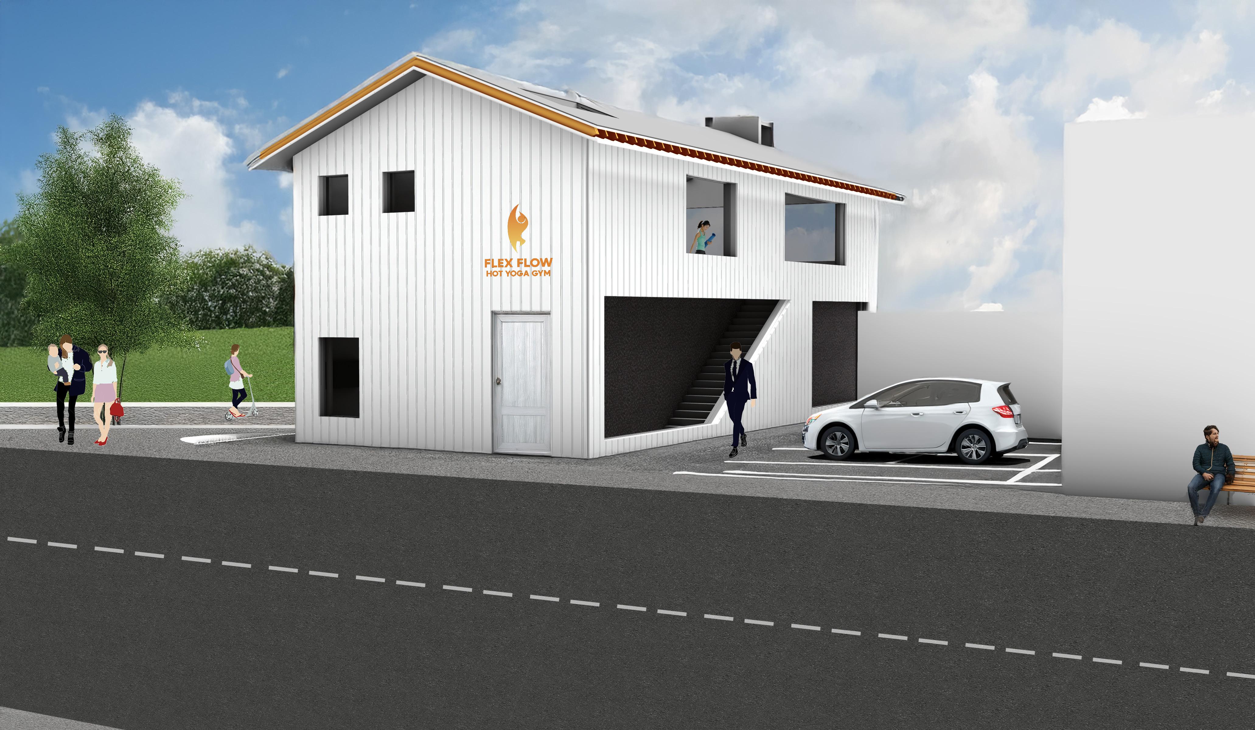
Our project design encompasses the wide climate range in Toronto in order to passivly heat and cool a pop-up gym space within a mildly urban neighborhood just outside the city.
Paige Doherty, Ines Juguet, Zachary Blick
Table of Contents
Designing for Climate
Environmental Analysis
Conceptual Design
Interpretive Site Drawing
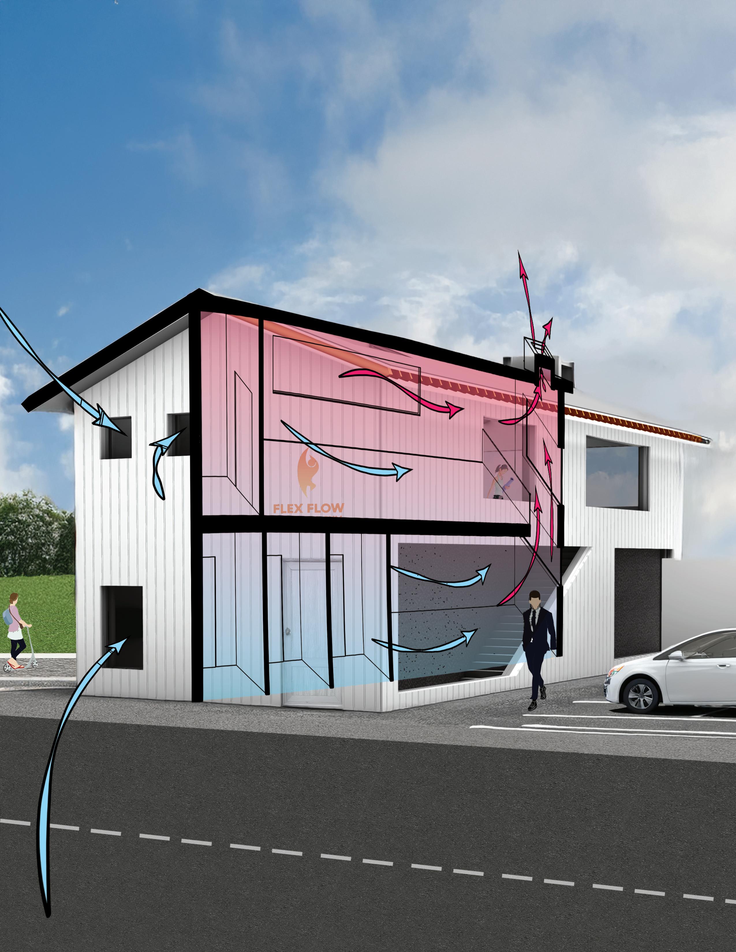
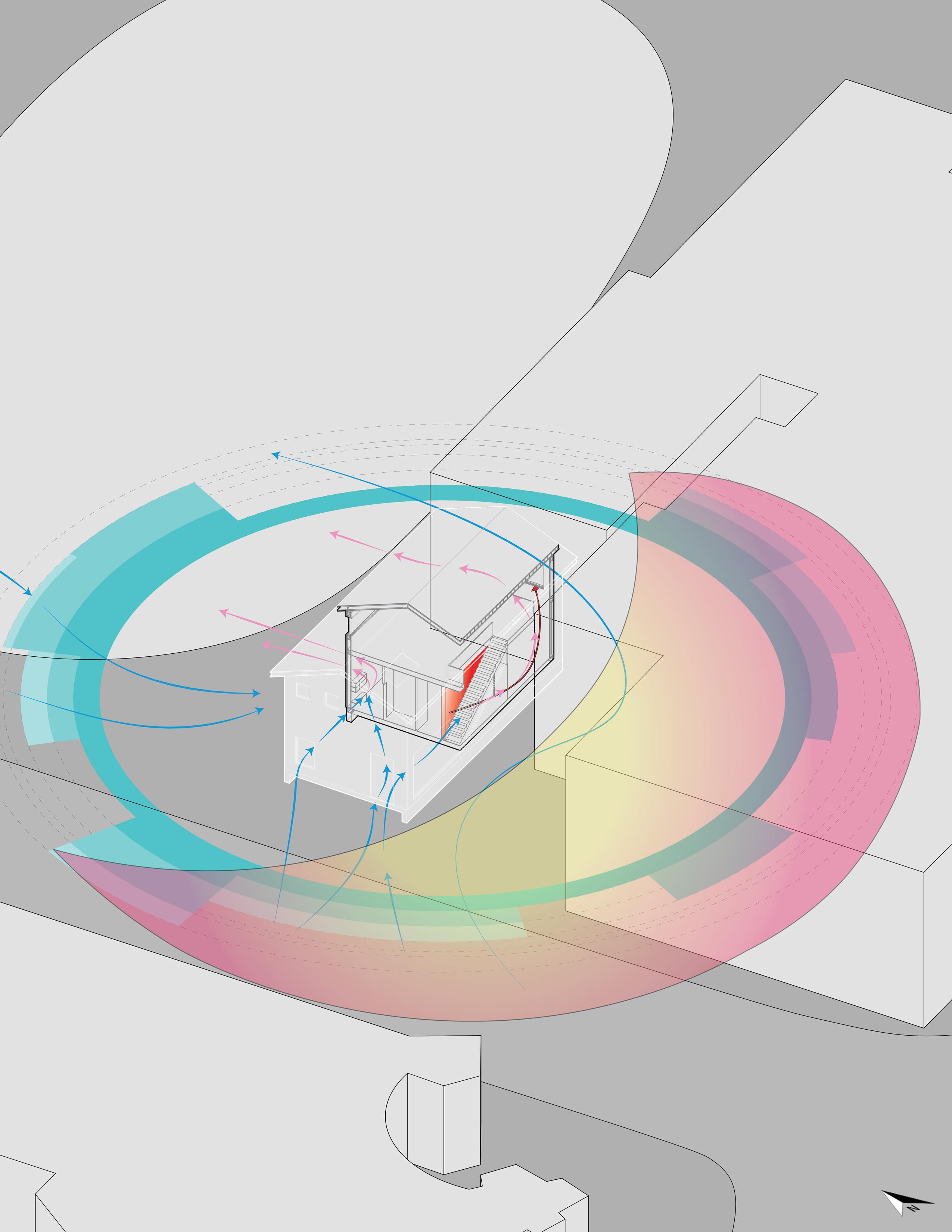
Passive Design in Action
Passive Design Strategies
Applied Strategies
Concept Design Drawings
Designing the Envelope
Corner Details
Cycle Analysis Report
Analysis Model Chunk Corner Assembly Model
Part I - Designing For Climate
Synthesis of year-round climate analysis data of Toronto, in order to configure the primary conceptual design of our gym.
Our Site Temperature
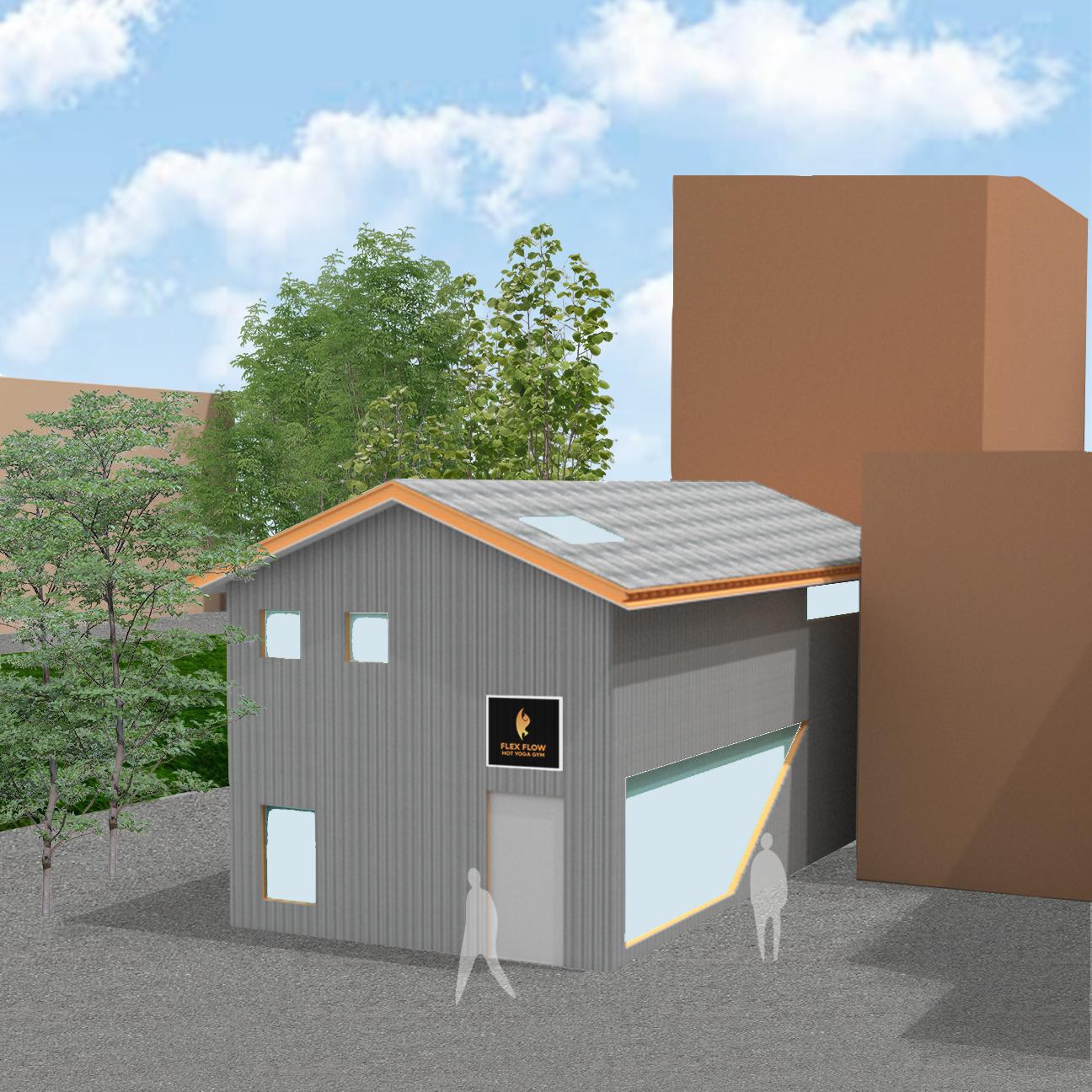
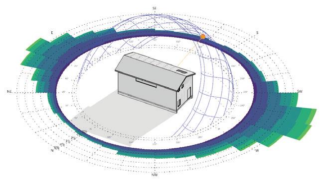
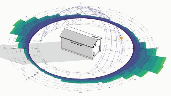
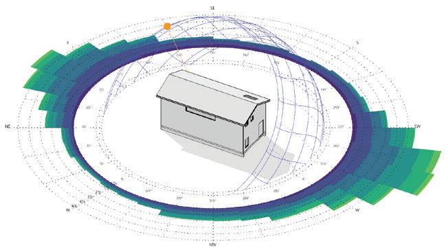
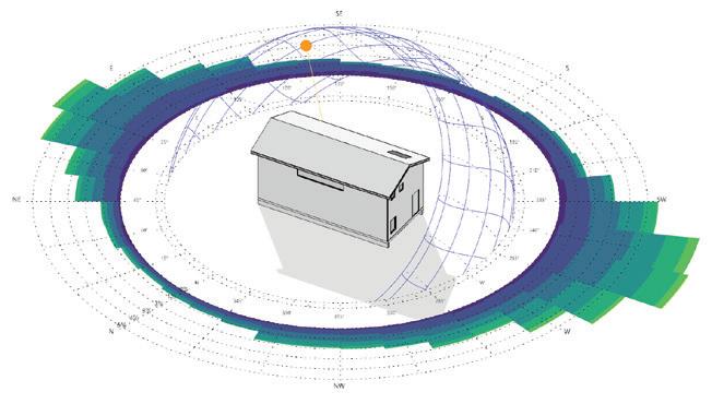
Sun Cloud Coverage
The site of our project is in the DFA zone in the Koppen Climate Classification, meaning it experiences hot, humid summers, and cold winters. This can be seen above with the sunpath diagram and windrose overlay, as well as temperature which vary greatly throughout the year.
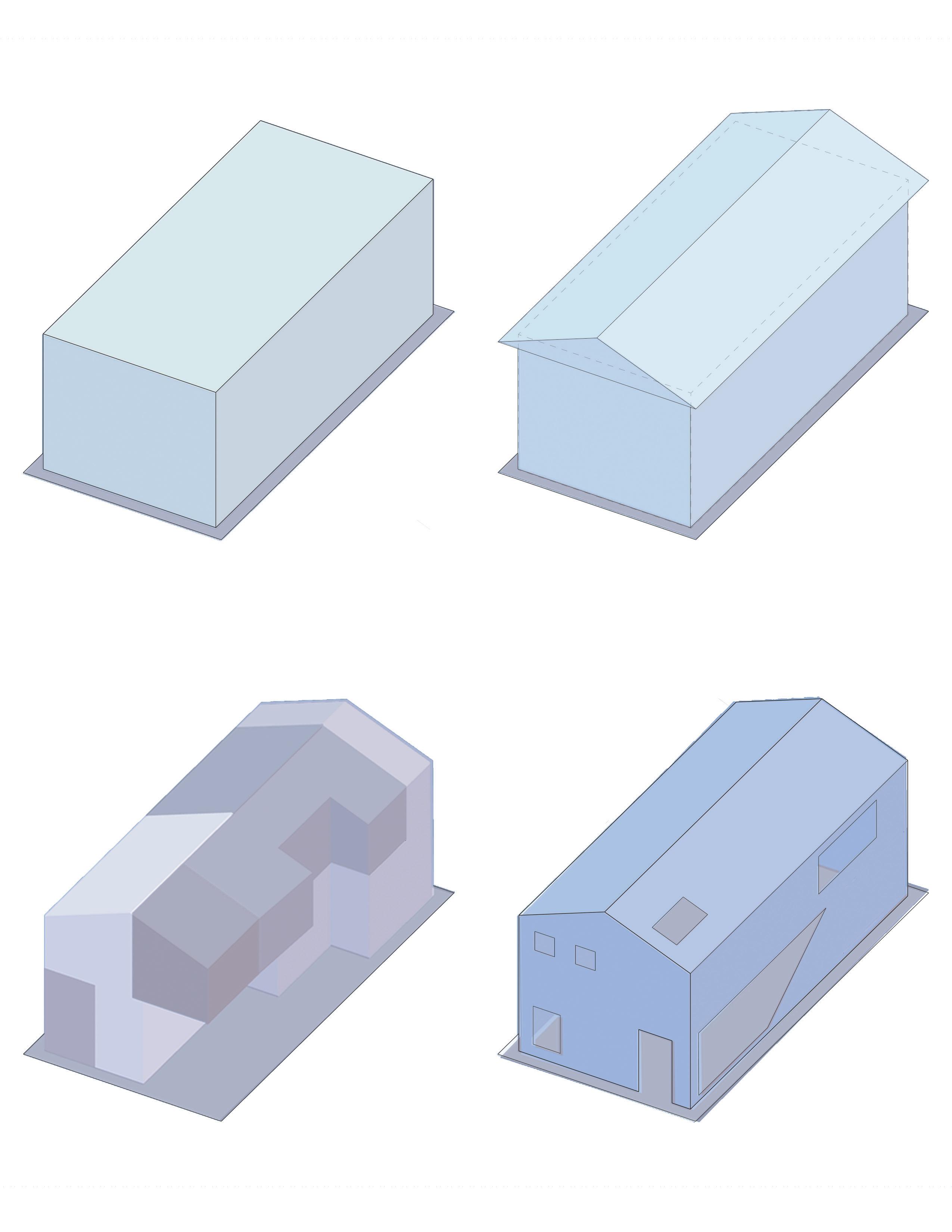
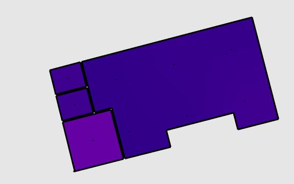
1) Extrude Box 2 storeys
2) Gable Roof and Overhang based on sun path
3) Divide Program based on the concept that hot air rises
Sun angles throughout the year used to calculate angle of roof and overhangto maximize the amount of sunlight that hits the south facade
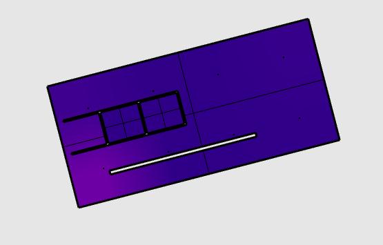
4) Window Placement based on wind direction and sun path skylight on angled roof to allow sun to directly enter the sauna
cross ventilation windows as wind flows from the west
Trombe Wall on South facade to trap heat during cold months, and privacy purposes
Bathrooms
Locker Room
Sauna
Hot Yoga Studio
Gym
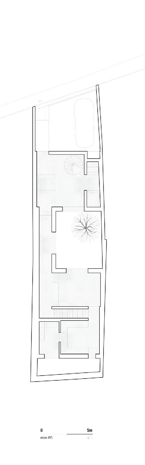
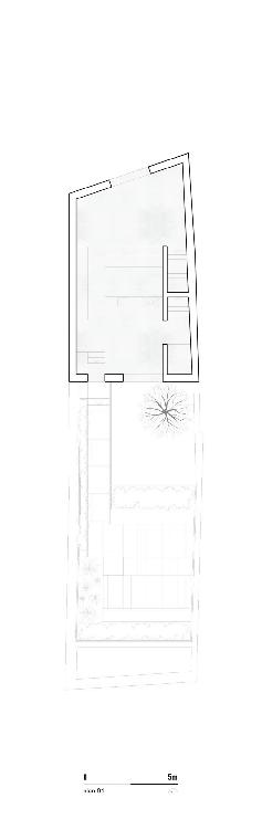
Our hot yoga gym design uses the principle of heat flow that hot airm rises due to the difference in densities in order to program its spaces. The hot yoga studio and sauna are located on the top floor, which overlooks the floor below allowing for vertical stack ventilation and the warm air to rise up. There is also a CMU trombe wall which aids in heat retention during the cold Toronto winters.
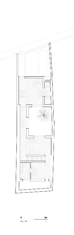
Ground Floor Plan / Scale 1/8” = 1’0”
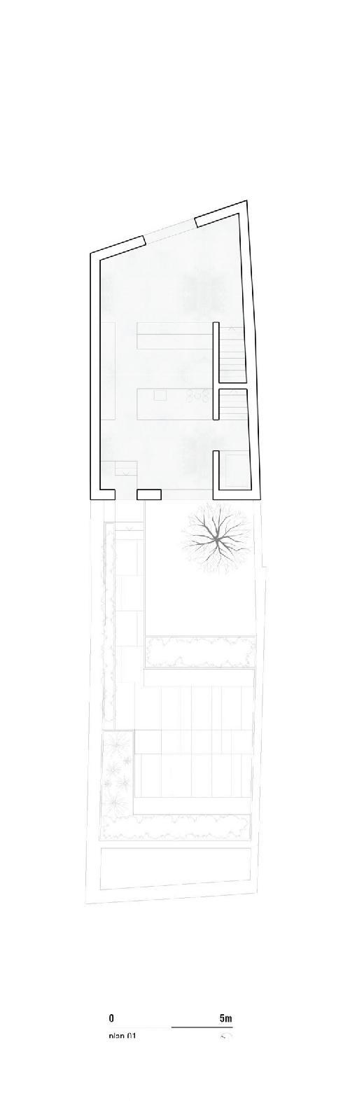
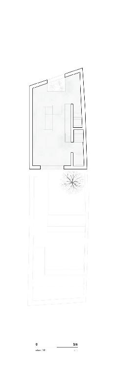
Second
= 1’0”
Jun 21. Sun Angle: 70 Degrees
Dec 21. Sun Angle: 40 Degrees
Sloped Roof Responds to Sun Angles
Sun blocked by neighboring building during winter months
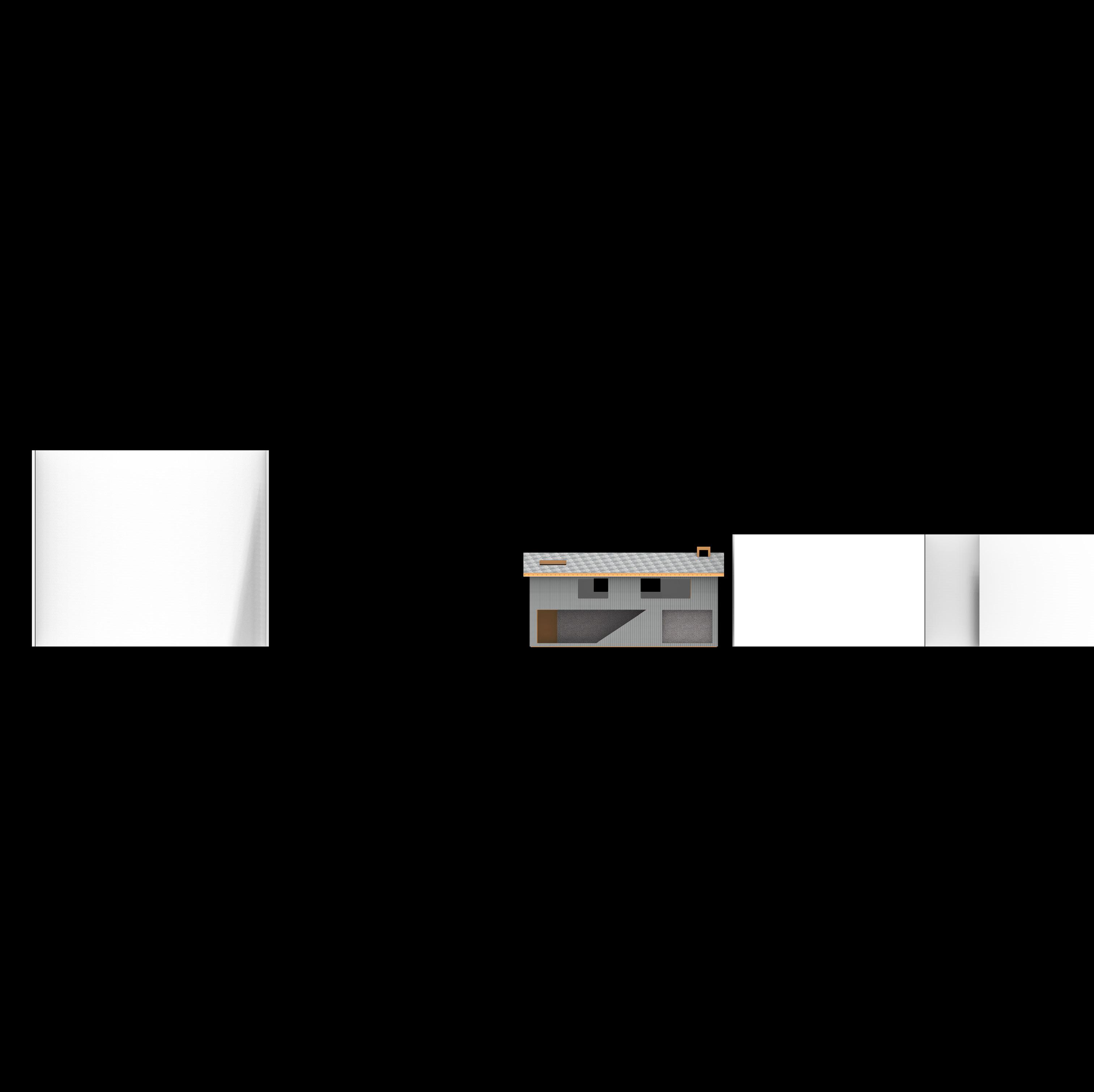
Elevation / Scale 1/16” = 1’0”
Trombe Wall
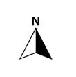
The open floor plan allows for the flexibility of spaces, as well as uniqueness of classes which can be offered in our studio. The materiality of the building allows for a warm, welcoming feeling on the interior, while still feeling like a gym/yoga studio.
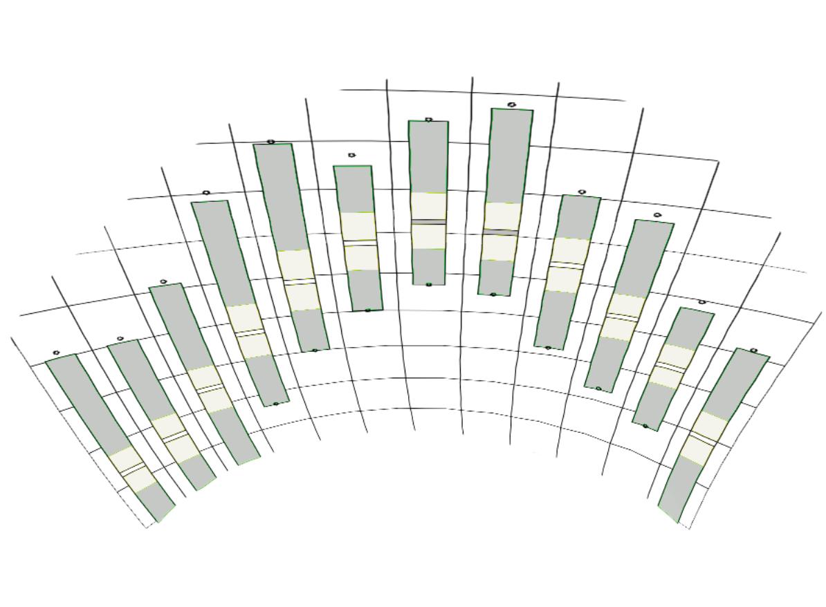
Annual Sun and Wind Rose
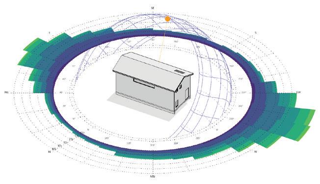
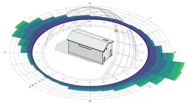
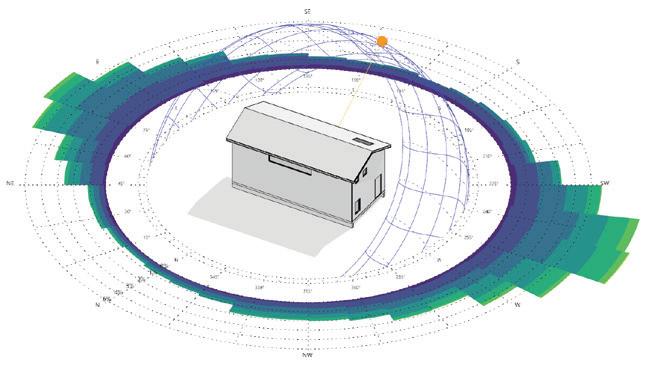
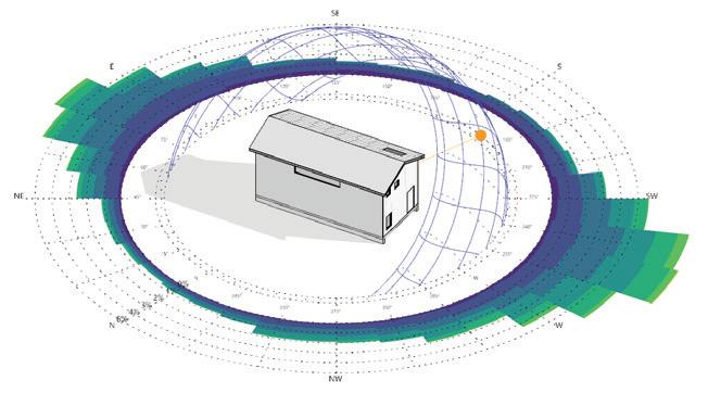
Below shows the suns positioning and the way it hits our buildings and casts shadows throughout the year at different times of the day. In addition, it shows the wind direction and velocity and the different times of year and day. This is important as it will show us how our building mass interacts with the sun and wind throughout the year since
Jun. 21 / 9 AM
Sep. 21 / 9 AM
Jun. 21 / 12 PM Jun. 21 / 3 PM
21 / 12 PM
21 / 3 PM
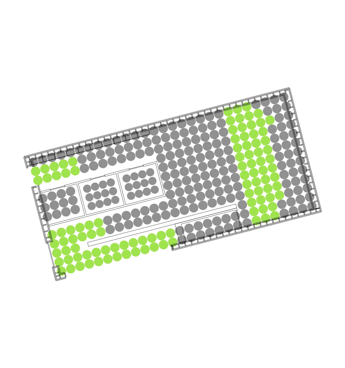
Our project is recieving far more daylight from the sun on the top floor than the ground floor. This is due to adding a trombe wall to trap the heat, however it blocks much of the natural light from reaching the gym space on the bottom floor, so electrical lighting would be needed to supplement the natural light in our building.
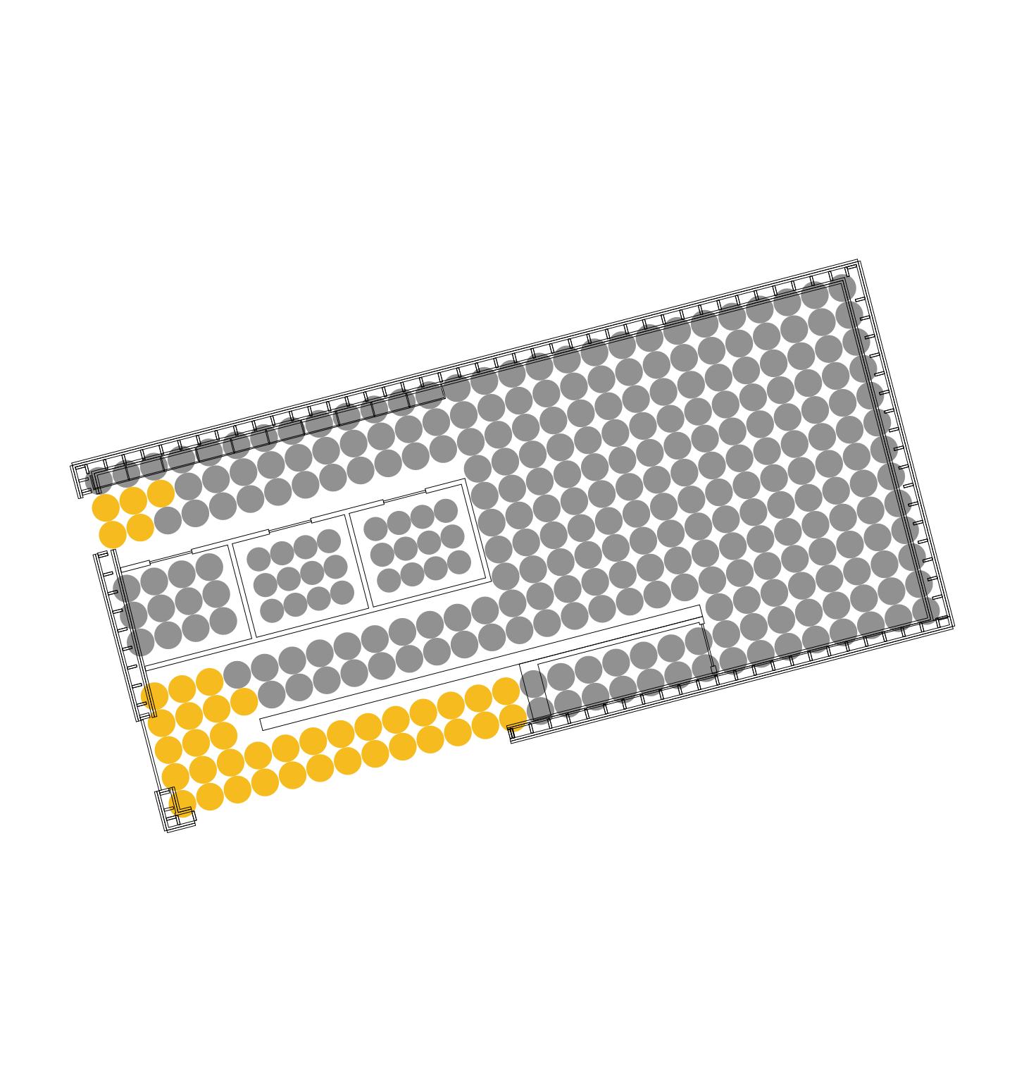
Our project has extremely finite amounts of radiation present at almost all areas besides from that closes to the windows where it slightly increases to a healthy amount due to the sun getting trapped in the building.
Part II - Passive Design in Action
Due to the high year round, as well as diurnal temperature variation of Toronto’s climate, our project will require both passive heating and cooling systems in order to mantain a comfortable interior temperature year-round.
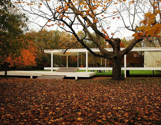
Passive Heating: Direct Heat Gain
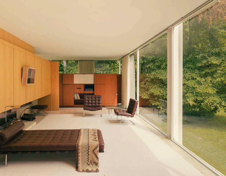
Farnsworth House, Ludwig Mies Van der Rohe Plano, Illonois
The Passive Heating Strategy used by Mies Van der Rohe in his Farnsworth House is Direct Heat Gain. The project uses thick slabs, combined with a glass enclosure system. The glass allows the sun’s short wave lengths to pass through the glass, but then the building traps the long waves in the building. The thick floor slabs absorb the heat and release it periodically over time, which gets trapped as heat in the
building as long wave radiation. The solid partition walls within the house are located set back off of the south facade, in order to allow the heat to become trapped in the building.
June 21, 12 pm Dec. 21, 12 pm
South Facade
Thick Floor and Ceiling
Sun’s Short Waves
Trapped Infared Radiation (Long Waves)
South Facade
Thick Floor and Ceiling
Sun’s Short Waves
Trapped Infared Radiation (Long Waves)
Passive Heating: Indirect Heat Gain (Trombe Wall)
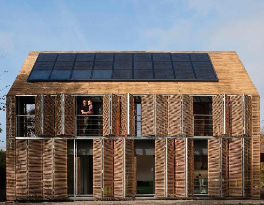
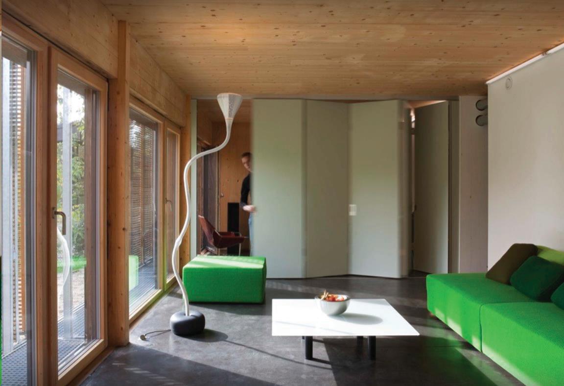
Aire De Repos, Atelier Craft Paris, France
Aire de repos, or “rest area”, uses the principles of indirect heat gain, through the use of a trombe wall. The south facing facade is entirely glass, with a set back trombe wall, which traps and stores the incidental heat in the front of the building, in order to redistribute it throughout the space as needed.
Trombe Wall
Trombe Wall
Trombe Wall
Glass Enclosure
Glass Enclosure
Glass Enclosure
South Facade
Trapped/Stored Heat
Short Sun Waves
Passive Heating: Isolated Gain
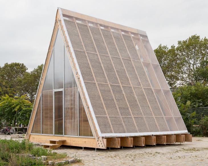
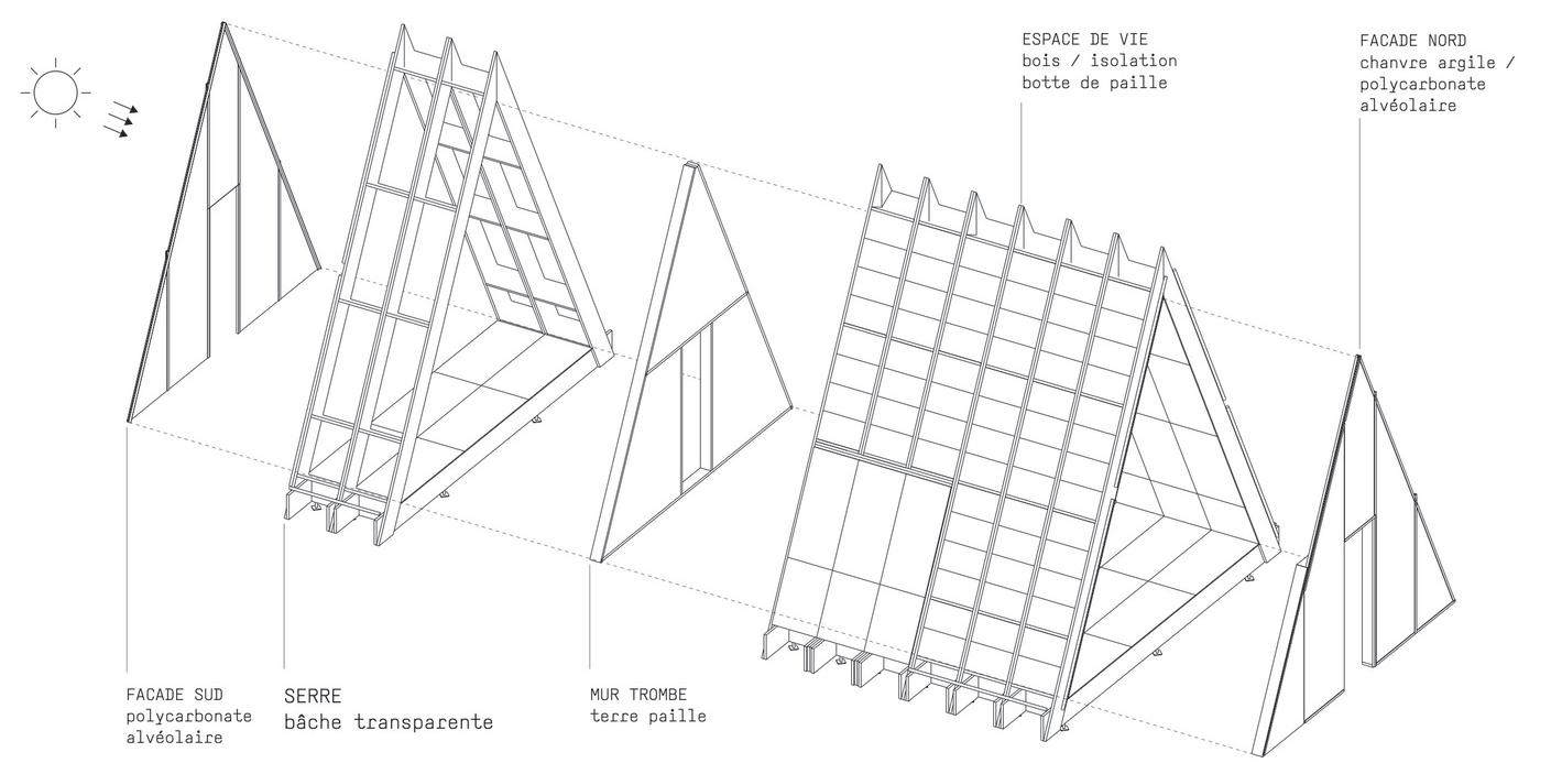
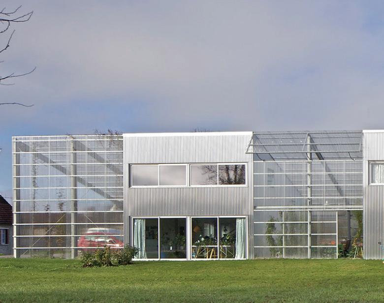
Maison+Agence, Herard & da Costa Neuville-sur-Seine, France
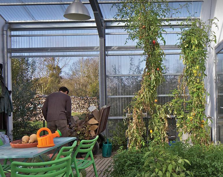
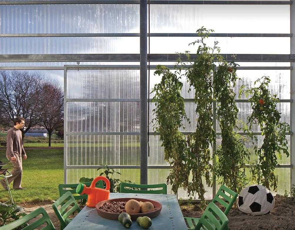
Maison + Agence by Herard & da Costa Implements Isolated Heat Gain as a passive system to allow for more effect within the house. The house is made of transparent polycarbonate and aluminum sheets, forming a greenhouse between each living space. The Greenhouse properties allow the building to capture and store solar energy. To best accomplish this, they have faced the slope of the facade
Thermal Mass to Absorb Energy transparent polycarbonate
southward, allowing for most heat gain to warm up the interior during the day. One night begins, the temperature winds down, and the building slowly realizes energy. Another perk of this space is that it allows for the growth of plants in all seasons, which was deemed essential for the site of this project.
heat spreading throughout the house
& Da Costa ArchDaily.” Accessed October 16, 2024. https://www.archdaily.com/545117/maison-agence-herard-and-da-costa?ad_medium=gallery.
/
“Maison
Greenhouse Section
Greenhouse
House Office Garage
+ Agence
Hérard
Passive Cooling: Cross Ventilation
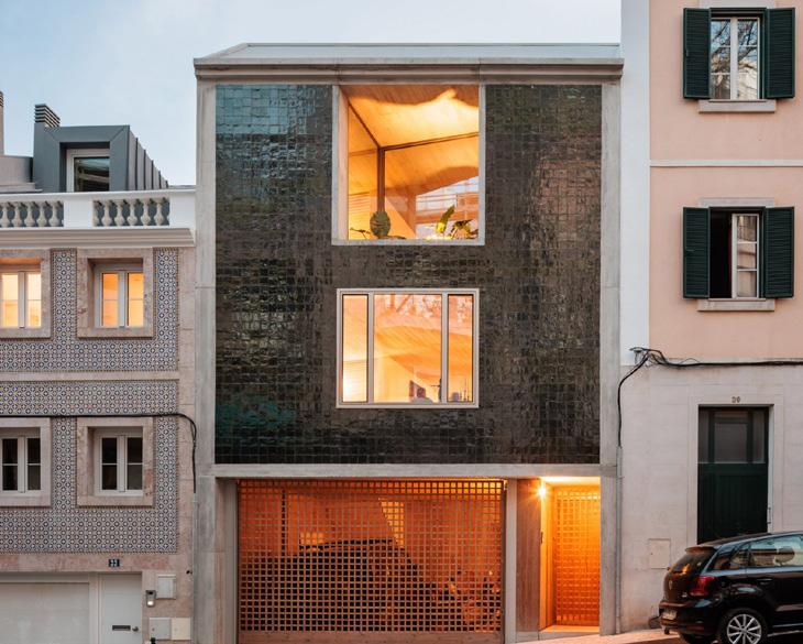
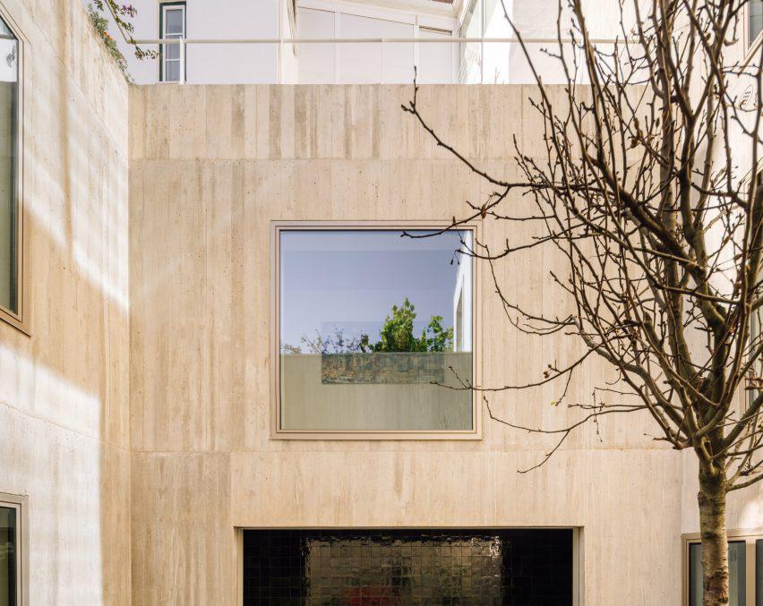
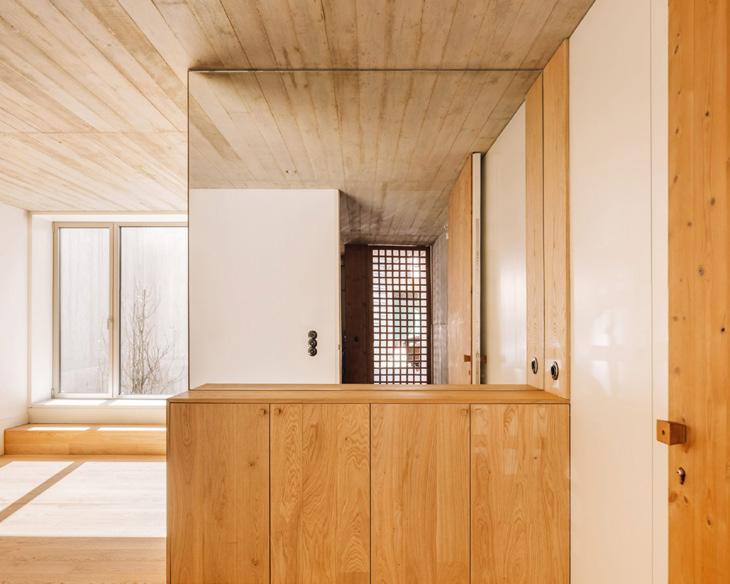
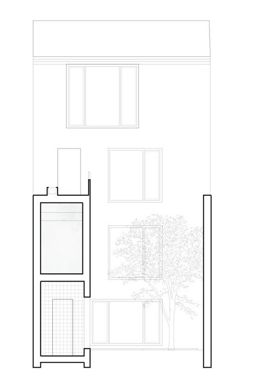
Lisbon Residence, Bak Gordon Arquitecto Lisbon, Portugal
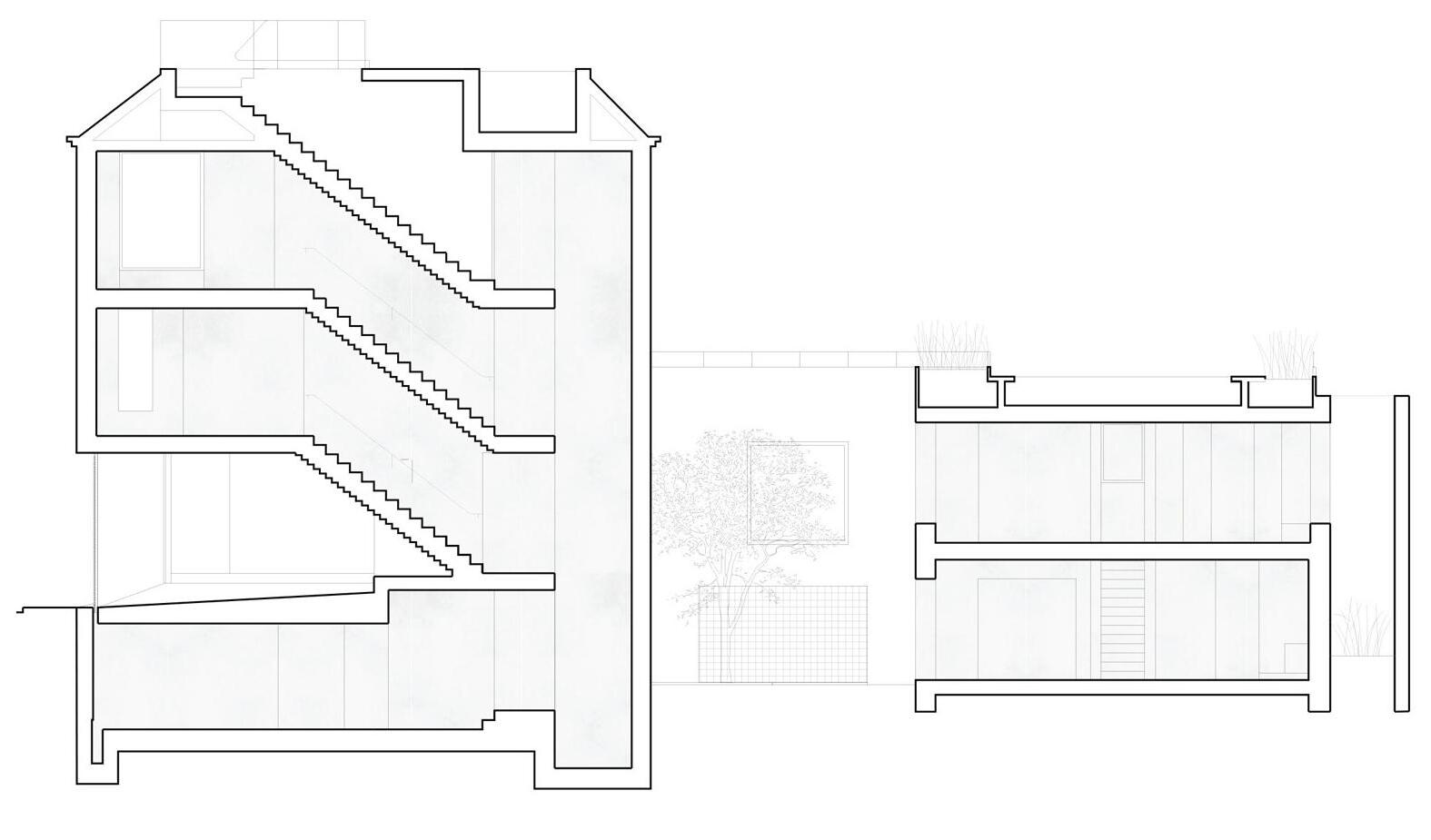
The passive strategy of cross ventilation is used in this Lisbon residence, designed by the Portuguese studio Bak Gordon Arquitecto. This strategy relies on wind flow to carry the heat through each floor, escaping through perforations of the opposite side of each room. This home uses an exterior courtyard in which the hot air, carried by wind, can escape into. The home also reflects the ideal footprint
for cross ventilation which is a elongated rectangle with minimal internal divisions, allowing a concentration and ease of wind flow. Wind pressure a high difference between interior and exterior temperature is essential to keep with home cool.
Wind pushes the air though each indiviual above ground floor level.
Air Enters and Exits through windows (perforations in the enclosure)
Air Enters as Cool Air and Released as Hot Air
The Wind that enters and ventilates each floor is released into the inner courtyard that connects the 2 halves of the building. Allowing hot air to escape.
Passive Cooling: Stack Ventilation
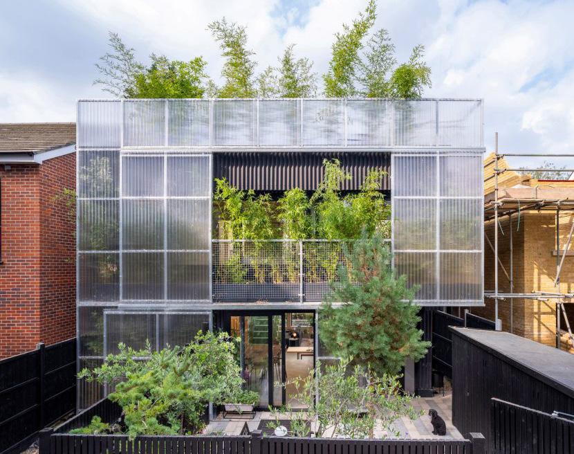
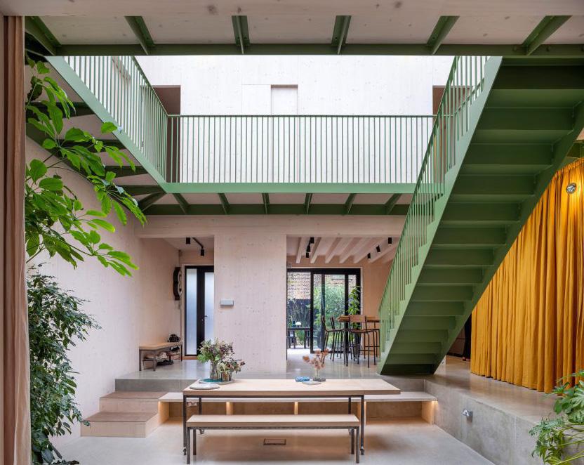
London Home, Hayhurst and CO London, England
Stack Ventilation leverages the vertical movement of air. It doesn’t depend of wind, instead on the fundamental idea that hot air rises and that cool air will
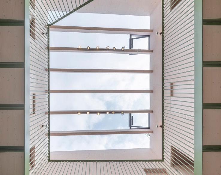
The passive strategy of stack ventilation is maximized through the interior courtyard that allows for air to move between floors and escape at the upper most point through opening in the sky light and the placement of windows.
The Sky light atop the atrium, which opens up acting as an exhast to let hot air Escape.To maximze the stack effect the opening is at the upper most point and as large as possible
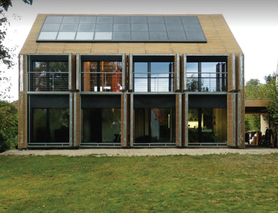
Passive Cooling: Night Ventilation
Passive House, Karawitz Architecture Bessancourt, France
The house uses a double-faced, open facade on the south side to limit energy loss. Throughout the day, the floor plates were designed to absorb energy,
creating solar heat gain. The only nonwood element used in the project was concrete to allow for said conditions. As the temperatures cool, residents open the windows, carrying the hot air outdoors and creating airflow. When this occurs in the building, it resets it for a cool start to the day.
Thermal Mass Heat Energy Lost
Applied Passive Stragey 1:
Heating - Direct Heat Gain
Rationale:
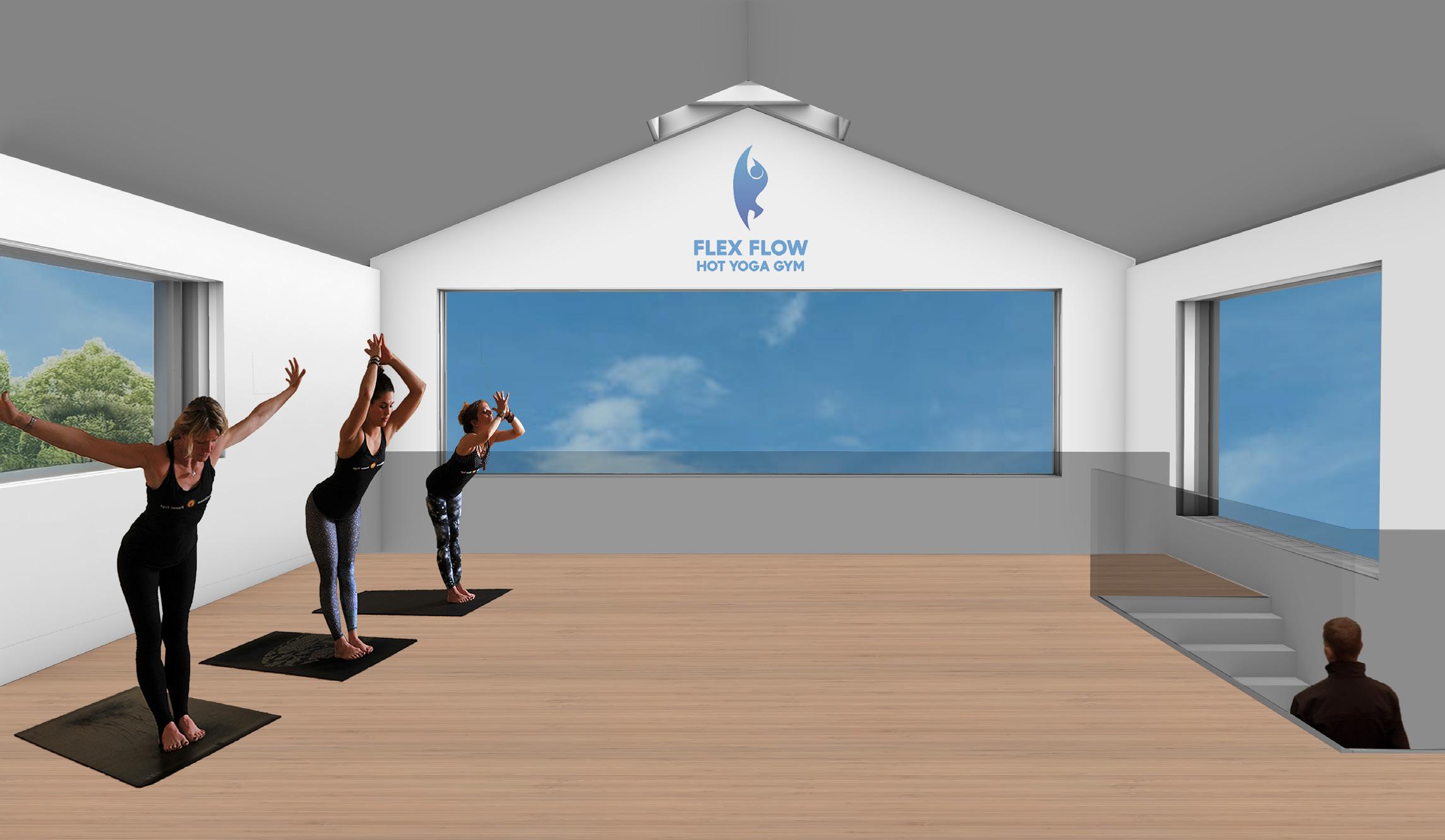
In order to passively heat our building, one strategy that we utilized is the concept of direct heat gain from the sun. In order to do this, we had to make sure that our building’s south facade was angled less than 15 degrees (it is 14 degrees) from the south in order to ensure maximum sun exposure. In addition, our project utilizes thick concrete slabs in order to absorb and store the heat. The windows on the top floor were extended to span from the floor to the ceiling, and another window was added in order to maximize the exposure to sunlight. The windows are heavily insulated to prevent heat loss at night and the sauna has a pitched roof skylight, but no windows on the exterior for privacy purposes. As a gym, the excess windows on the south facade not only acts as a natural heating system, but also adds to the experience of working out, by allowing natural light in to help for aesthetic purposes for the building occupants.
Precedent Study: Farnsworth House
Concrete Floor slabs
Pitched Roof Skylight for Sauna
Concrete Floor slabs
Initial trombe wall placed 4 feet in from left
Rationale:
We implemented a trombe wall, which is a 8” masonry wall that is set back from the glazing in order to capture heat in a more confined space and release it throughout the day. This strategy also must be placed on the south facade of the building, therefore in order to balance the amount of direct sun exposure and indirect sun exposure that our building had on the south facade, we looked at the different building programs and decided what we want to be private vs public. The staircase wall can also be viewed as a semi-trombe wall, despite being placed more than 6” away from the glass as it not only separates program but will trap the heat which goes through the window in a confined space, and this heat will rise and act as a passive system for heating the upstairs hot yoga area. We thought about the potential addition of a trombe wall on the south facade in the sauna, however believed that this wall would make it too hard to control the exact temperature of a sauna, which would most likely need to utilize active systems in order to maintain its severe heat.
Initial trombe wall
Secondary trombe wall 2’’ away from window to store heat more effectually
Cross Ventilation attempts to create a natural flow of air across a building or through a space in order to remove heat. Wind flows primarily from west to east in Toronto near our site so the west facade window is lower than the east windows.
The space’s long rectangular shape is benifical in allowing for more air flow and better cross ventilation. The site is not too loud, with its location next to a park, and has decent air quality allows for this system to be sucssesful in its implementation. Even when outdoor air isn’t low enough to actually cool a space, if a breeze can be felt occupant comfort can be increased
Comfort Description -
The climate in Toronto can get pretty hot during the summers, but not too often, which is why it is important to be able to passively cool the space without implementing active energy systems. Our building utilizes cross ventilation from the west face of the building to the east face, in order to cool the bottom floor of the gym, as it is almost an entirely open plan. The windows are oriented with the lower one being on the west, and higher
being on the east so that as the wind flows from west to east throughout the building the hot air will rise, and exit the building through the higher window. The project utilizes the cross ventilation along the long axis of the building, as it not only aligns with the direction in which the winds are coming from, but also allows for more room for the air to circulate, making it more efficient at cooling the space. Even
when the temperature outside is not low enough to fully cool the space, a cross-breeze can be introduced through opening the windows in order to make the gym space more comfortable for its building occupants.
Cross Ventilation relates to the horizationtal air flow and therefore it is important to have openings on each level. The west facade has opening on both floors to allow the air to enter and on the east facade there is a opening to allow the air flow to escape
It is important to note that since the gym already has a 2 story heigh ceilings on the east facade the additional window simply allows more air to escape quicker and easier.
The addition of the window that is higher up on the back facade now will allow air to circulate through the space and create a cross-ventilation condition in order to passively cool the open space in the lower gym floor.
Allow warms air to rise naturally, and it will be replaced by colder air below, double heighted space allows for this to be executed within our building. Warm air will be released from the building at a highest elevation, must add exhaust at highest point of the building and oriented away from the prevailing winds. This creates air current and pressure differentials that drive airflow through a building. It is a similar process to cross-ventilation and they can work together as hot air rise and will exit the building. The throat width is 6 feet by 25 feet, allows plenty of room for hot air to rise and escape
Comfort Description:
The stack ventilation system is effective in our project, and has the ability to work with the cross ventilation system, as it will allow our project to utilize both vertical and horizontal air movement. In order for the hot air to be efficiently pushed out of the building, the exhaust must be situated at the highest point of the building, and facing away from the prevailing winds. The double heighted space will allow the air to circulate vertically and create a constant flow of air throughout the project.
Air has no where to go once it rises, gets trapped and can not circulate. Exhaust was introduced above stacked floors in order for air to have somewhere to escape. It is oriented away from the direction of the prevailing winds.
Without the Vent, the Warmer Air had no where to escape, which could lead to issues like poor air circulation, increased humidity, potential mold growth, discomfort due to temperature fluctuations, and increased energy costs
The addition of the Vent is cruital in allowing hot air to escape and regulating the internal temperature
Wind comes from northward direction, least amount of windows \placed on this facade
Triple Glazed Windows to allow for best heat preservation in cold months
Building places at 14 degree angle to allow for maximum sun exposure
Most windows placed on south side to gain the most heat
Trombe walls placed on south side to gain the most heat
Ground Floor Plan
Double Heighted Space
Concrete Trombe Wall
Sauna
Hot Yoga
Locker Area
Gym
Open Floor Plan for ventilation
West line of buildings across street create a wind barrier, blocking some of the strong winds
Opperable exhaust to allow hot air out from stack ventilation when open, and trap heat when closed to heat the building when it is cold during the winter months
Sky light to directly heat
the sauna
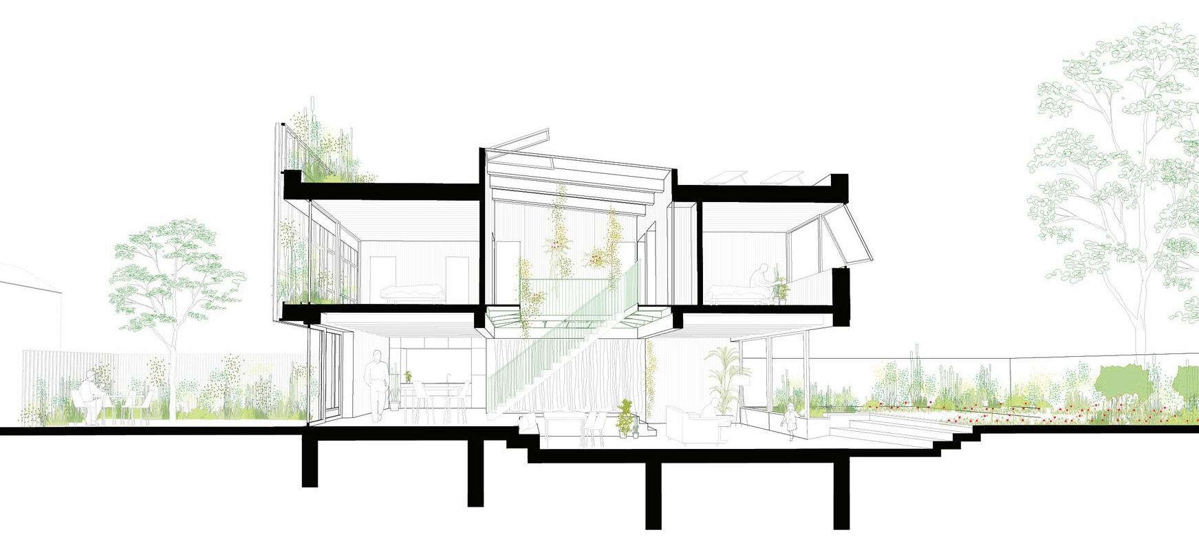
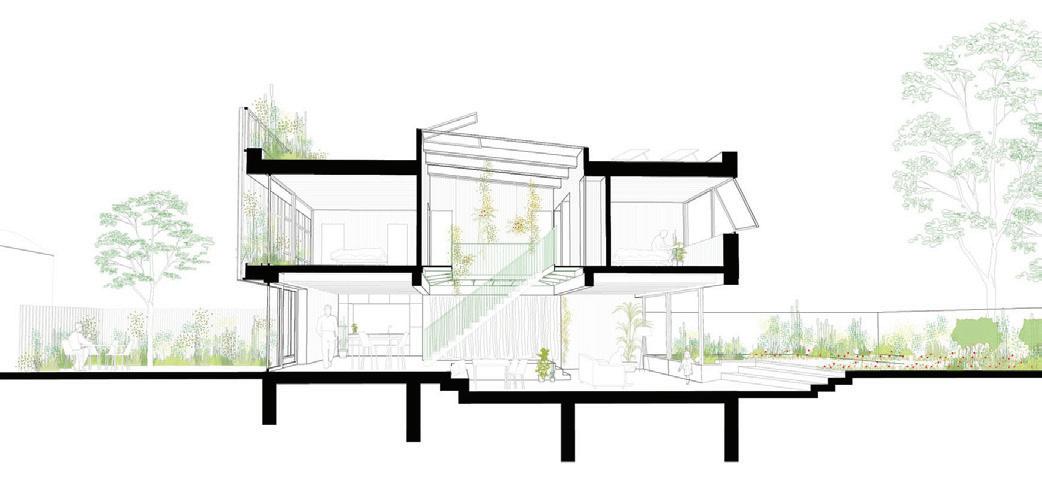
Section
Exposed Roof Structure with Finish on top and bottom for aestetic purposes
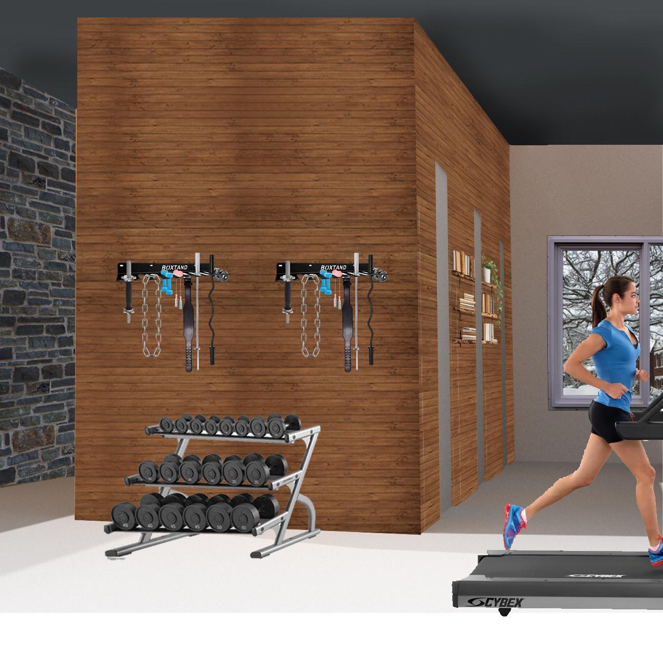
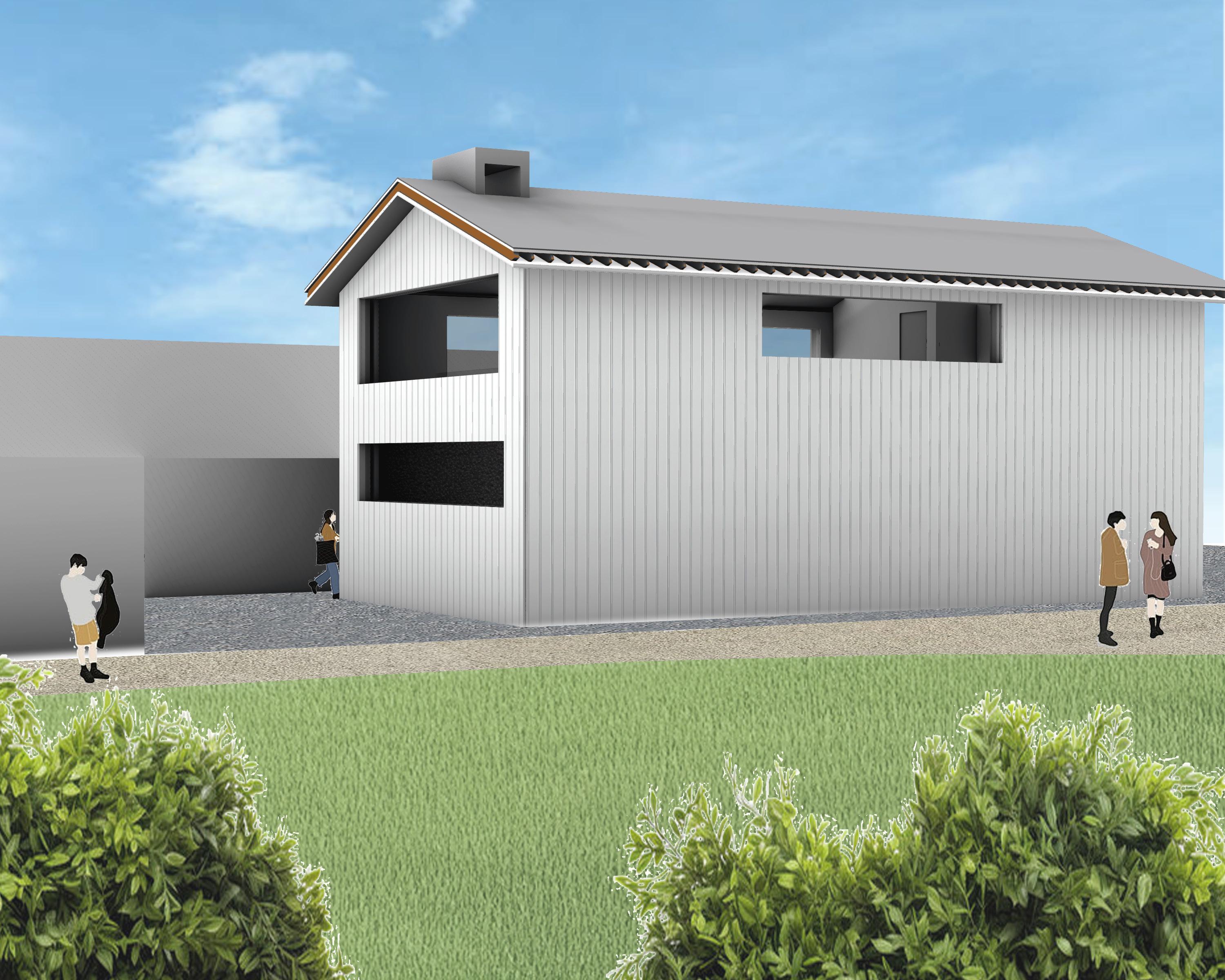
Light grey vertical siding is used as a envelope in order to prevent the excess absorption heat during the hot summer
Dark Concrete material choice used for trombe wall as it absorbs and traps heat through the glazing
Sloped Roof meant to maximize the amount of sun that will hit the sky light, as well as keep precipitation off the roof to stop flooding and weight build up
Although this mass may appear to be blocking the south facade, due to the high sun angle of Toronto, the glazing will still be hit directly by the sun during most months
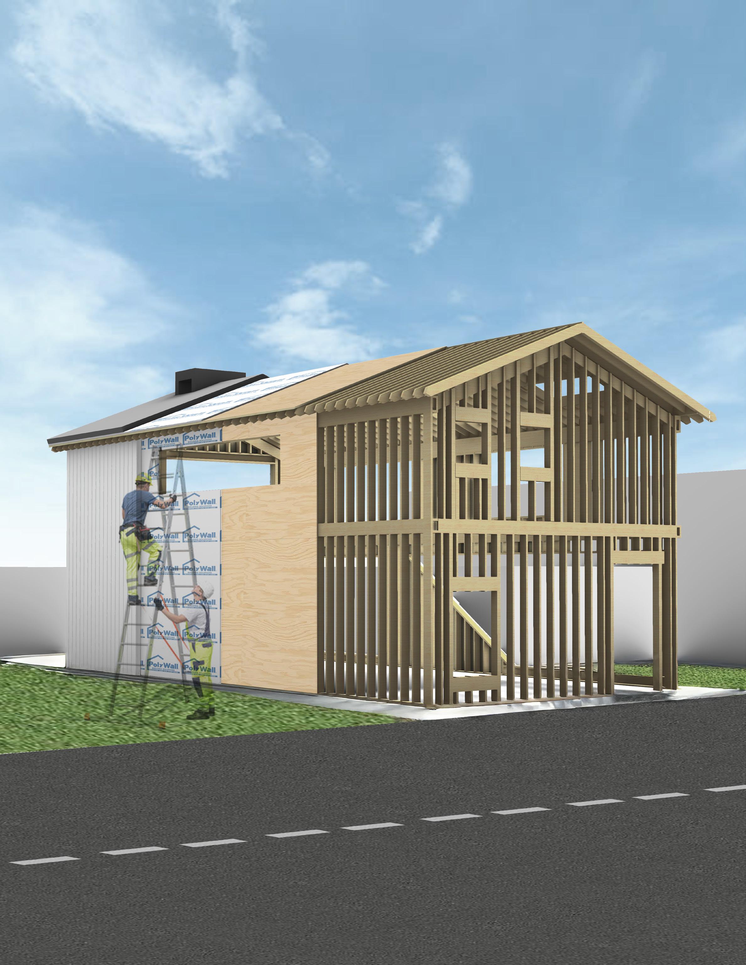
Light Frame Wood Structure Made of 2x4s
Plywood Sheeting
Peel-and-Stick
Waterproofing Sheet
Dark Grey Roofing
White Vertical Siding
Exhaust for stack ventilation/ passive heating
Proximity to park allows for it to not be extremely loud outside, despite being in the city of Toronto, which will allow for natural ventilation practices
Interior 2nd Floor Render
Part III - Designing the Envelope
Playing a crucial role in heat retention and exhaustion, this section of the project closely analyzes the developement of our structures envelope.
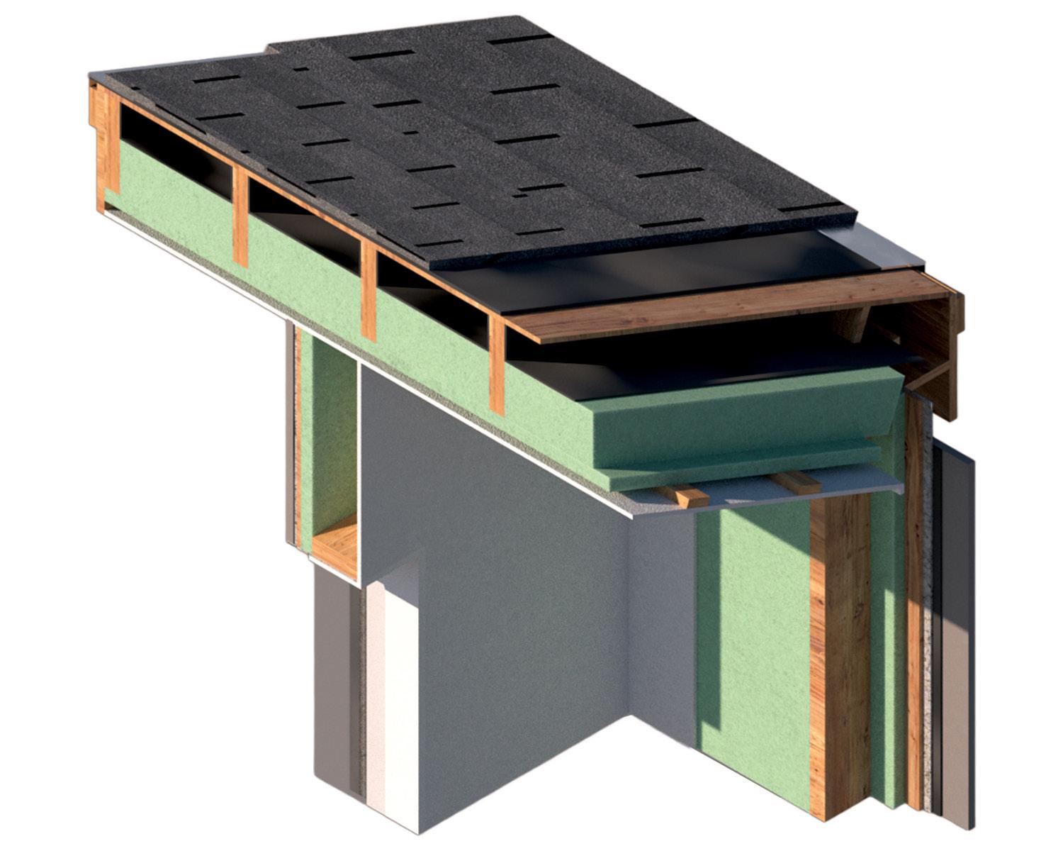
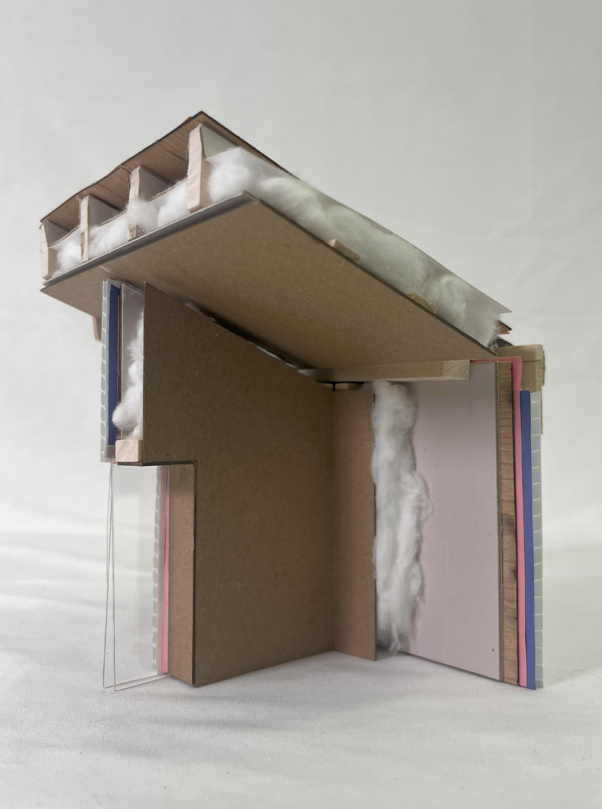
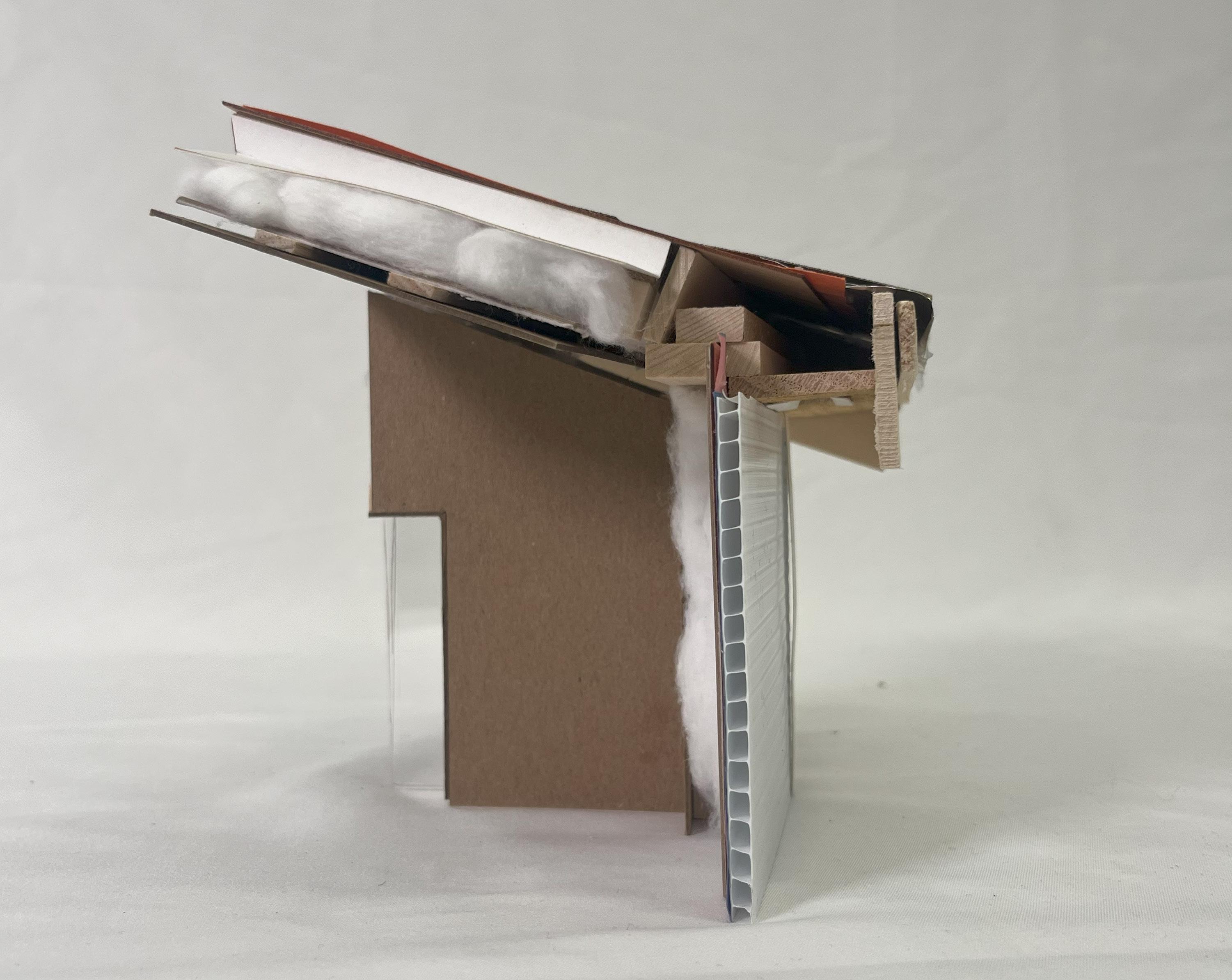
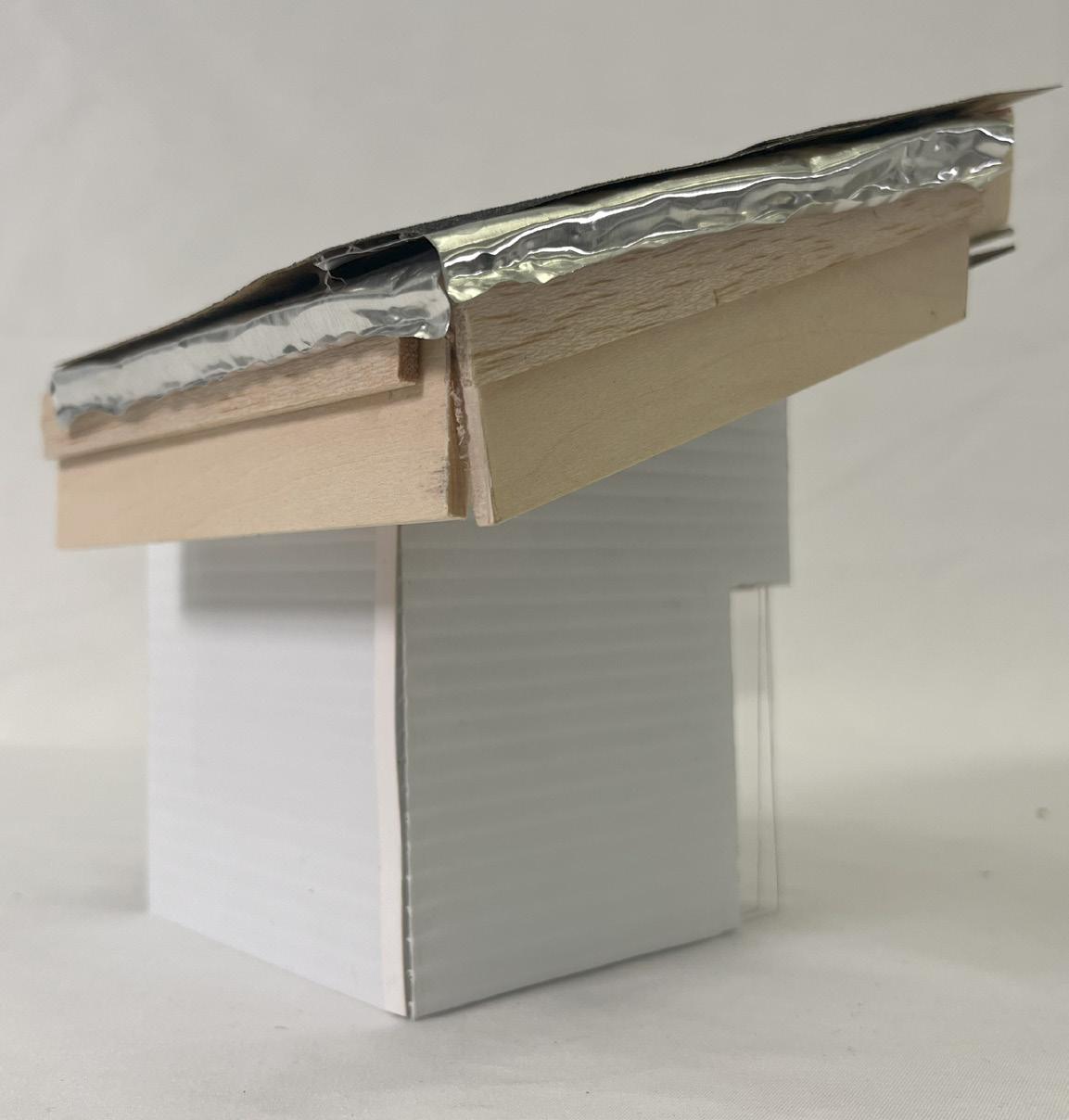
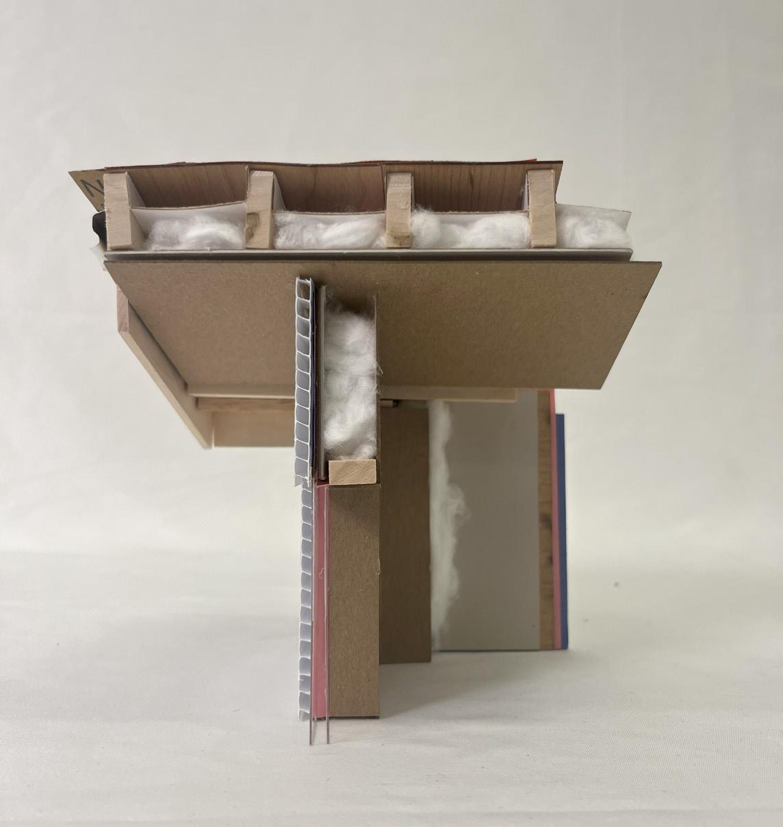
Roof Cut-Away Corner Chunk Model
This corner highlights a condition in our design where the angled roof meets the walls. In addition, there is a window present in the chunk, therefore it shows multiple typical condition, which is why we chose to detail it.
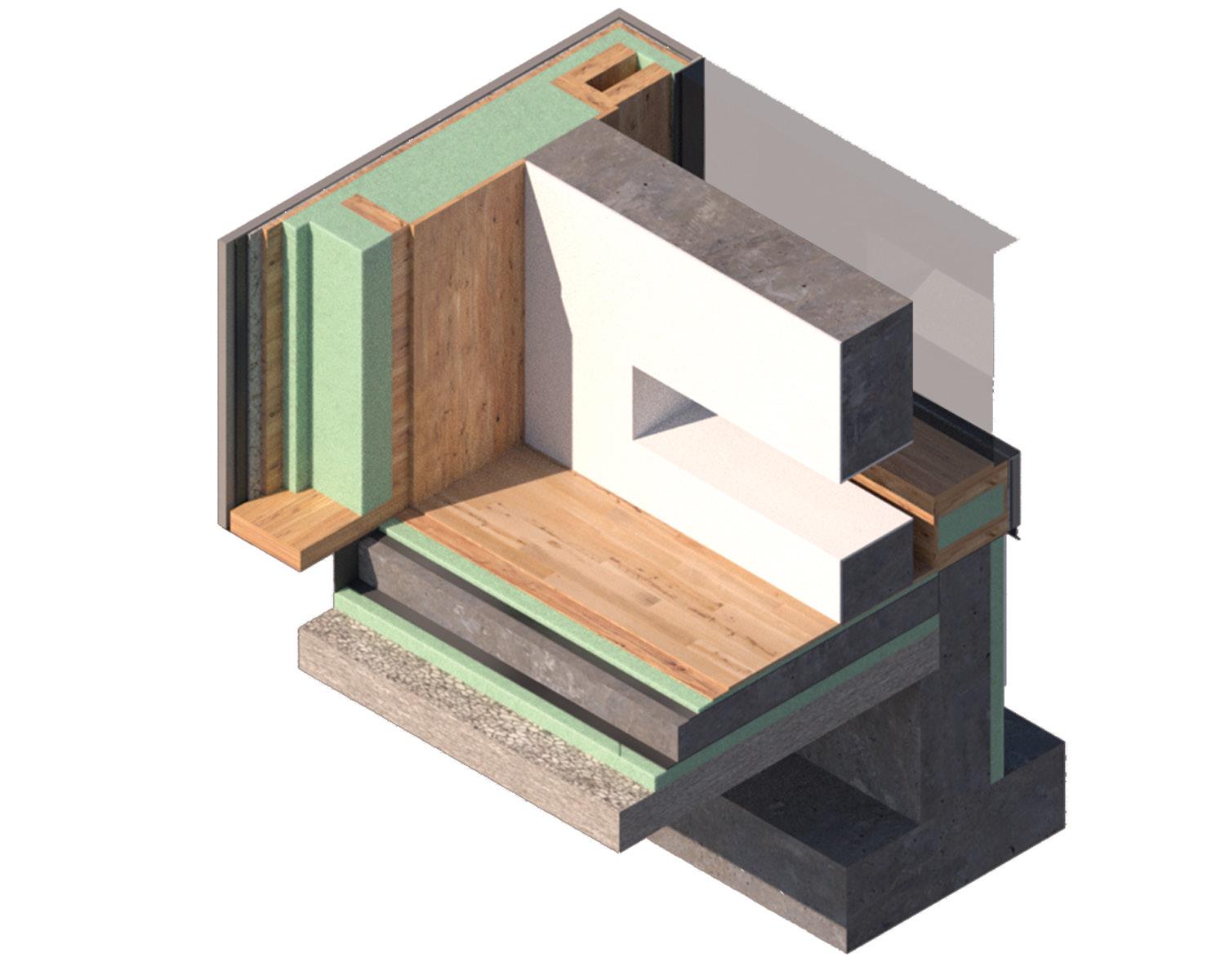
This corner exhibits the foundation meeting the floor, as well as a trombe wall which was implemented for heating purposes. The corner is able to successfully represent how the layers of assembly come together and meet at a large scale in very specific instances.
Floor Cut-Away Corner Chunk Model
Floor Cut-Away Chunk
Roof Cut-Away Chunk
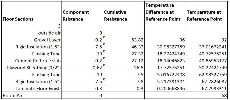
Gravel Layer
Rigid Insulation
Concrete Slab
Exterior Finish
Trombe Wall Glazing
Roof Underlayment
Metal Drip Edge
2x10 Wood Rafter
1x3 Wood Furring
Roof Section A
Roof Section C
Roof Section B
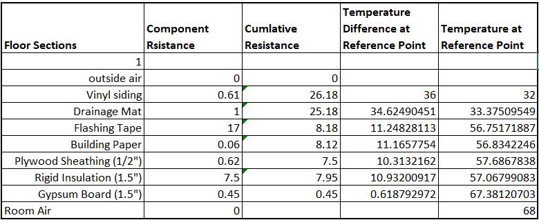
Floor Section A
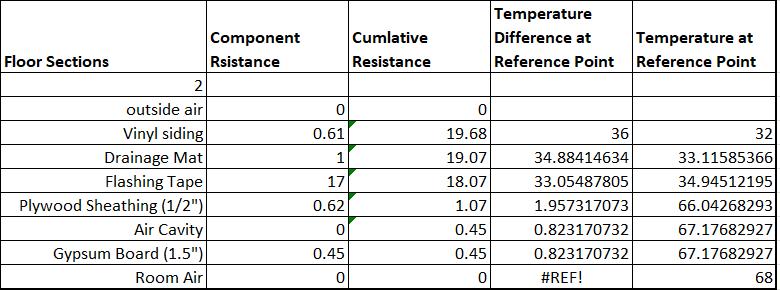
Floor Section C
Floor Section B
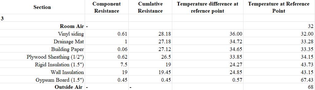
Roof Section - A
Scale: 1/2” =1’0”
Insulation Baffle
Metal Drip Edge Air Cavity Air Cavity Air Cavity Wood Furring
Exterior Finish
5/8” Roof Sheating Roof Underlayment Singles
1 1/2” Rigid Insulation Panel (Taped at All Joints)
Vinyl Siding
Drainage Mat
1/2” Plywood Sheating
Building Paper
Flashing Tape
1/2” Gypsum Board 1/2” Gypsum Board
2 by 6 Timber Frame Insulation
1 1/2” Rigid Insulation Panel (Taped at All Joints)
Double Pane Window
Roof Section - B
Scale: 1/2” =1’0”
Roof Underlayment
5/8” Roof Sheating
Cavity
2 by 6 Timber Frame Insulation
Cavity
1 x 3 Wood Furring
1 1/2” Rigid Insulation Panel (Taped at All Joints)
Cavity Insulation
1/2” Gypsum Board
Soffet Vent
Drip Edge
Exterior Finish
1 1/2” Rigid Insulation Panel (Taped at All Joints) Drainage Mat
Building Paper
1/2” Plywood Sheating
Cavity
Roof Section - C
Scale: 1/2” =1’0”
1 1/2” Rigid Insulation Panel (Taped at All Joints)
Interior Finish
Insulation
2 by 6 timber Frame (24” OC)
Flashing Tape Window Building Paper
1/2” Plywood Sheating
Air Cavity
Exterior Finish
Drainage Mat
Sheathing
1/2” Rigid Insulation Panel (Taped at All Joints)
1/2” Rigid Insulation Panel (Taped at All Joints)
Flashing Tape
Footing
Cavity Insulation
1/2” Rigid Insulation Panel
at All Joints)
2 by 6 Timber Frame
Drainage Mat
Flashing Tape
Exterior Finish
1/2 Plywood Sheathing
Air Cavity
Flashing Tape
Trombe Wall 1/2” Gypsum Board
Exterior Finish
Drainage Mat Building Paper
1/2 Plywood Sheathing 1/2” Gypsum Board
Cavity Insulation 1 1/2” Rigid Insulation Panel (Taped at All Joints) 1 1/2” Rigid Insulation Panel (Taped at All Joints) Flashing Tape Flashing Tape
4 in” Gravel Layer
Reiforce Slab
1/2 “ Plywood/ OSB Sheathing
Bill of Materials Report
Building Systems Yoga Studio Project:
Printed By: ZACK-XPS\Zachary Blick
Through our Liffe Cycle Analysis using the Athena Software, we found that the Global warming potential effects of our building is 1.22E+05, which is a high amount of pollution. An additional concern that we found in our project is the depletion of non-renewable energy resources. These two factors have the highest environmental impacts of the measured outputs. These numbers were determined based on the building assemblies and materials that we inputted into the software.
LEED LCA Measure Report
Project: Building Systems Yoga Studio
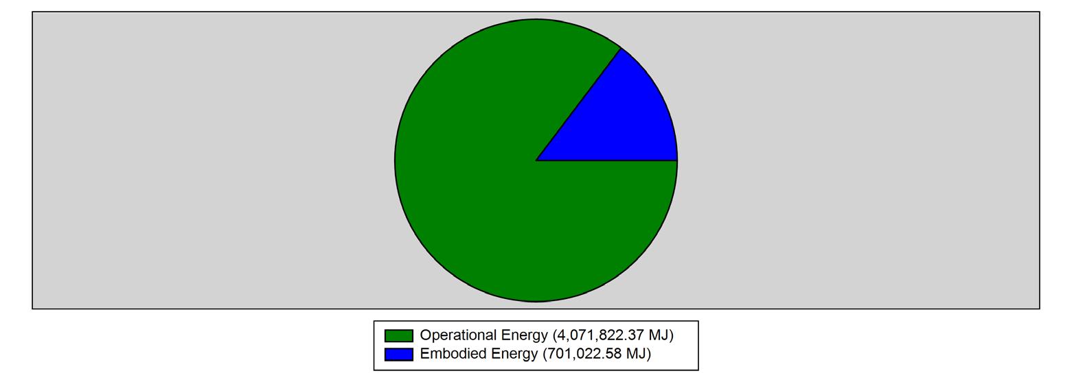
As you can see in the diagrams presented, our project uses a higher operational energy in both the fossil fuel consumption, as well as the global warming potential from (A to C). This is largely due to large window sizes and heating in a cold climate. Despite the passive heating strategies that we implemented, the climate in Toronto inevitably requires the use of active heating and cooling strategies and their is an extremely large variation in the year-round temperature. This is evident through the fossil fuels consumed in our project over the course of its life cycle. Because of our lower embodied energy values, we found it applicable to implement better active heating systems when needed.
vs Embodied Global Warming Potential (A to C)
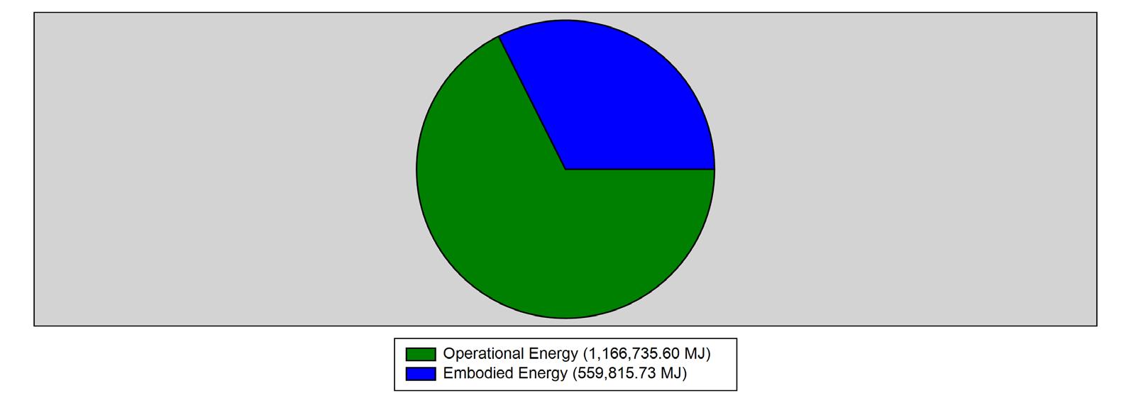
The total primary energy consumption reiterates our previous points on the high levels of opperational energy that is needed for our building throughout its life cycle. It is important for us to use this information to try to improve our design and minimize the opperational energy output to not only save money for our building, but also limit the effects of global warming.
Operational vs Embodied Total Primary Energy Consumption (A to C)
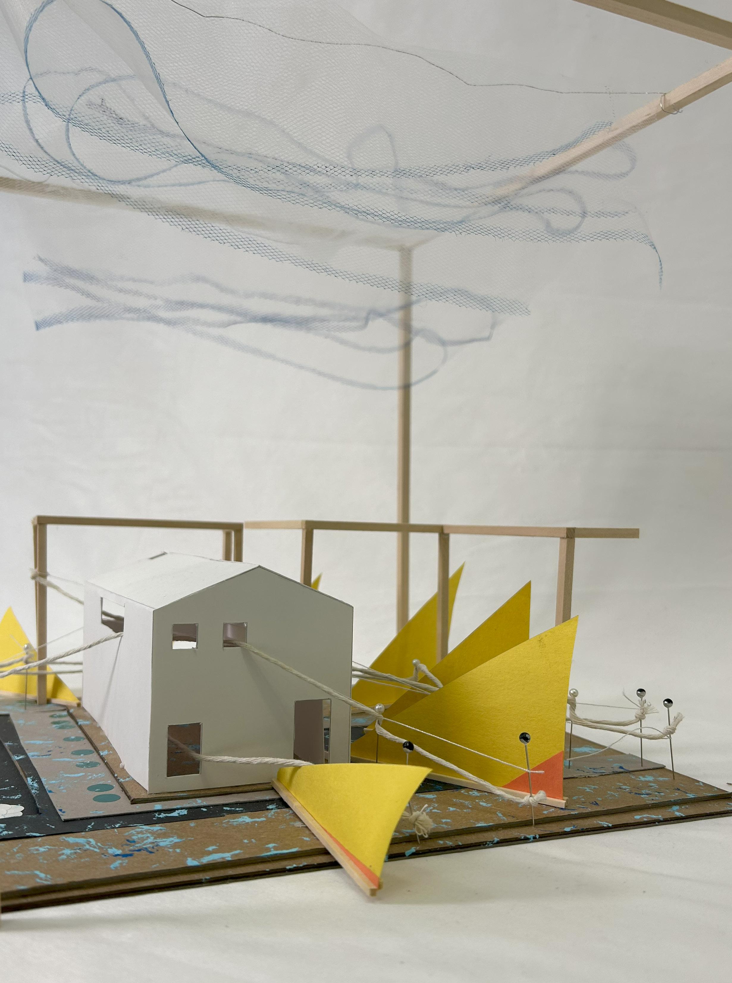
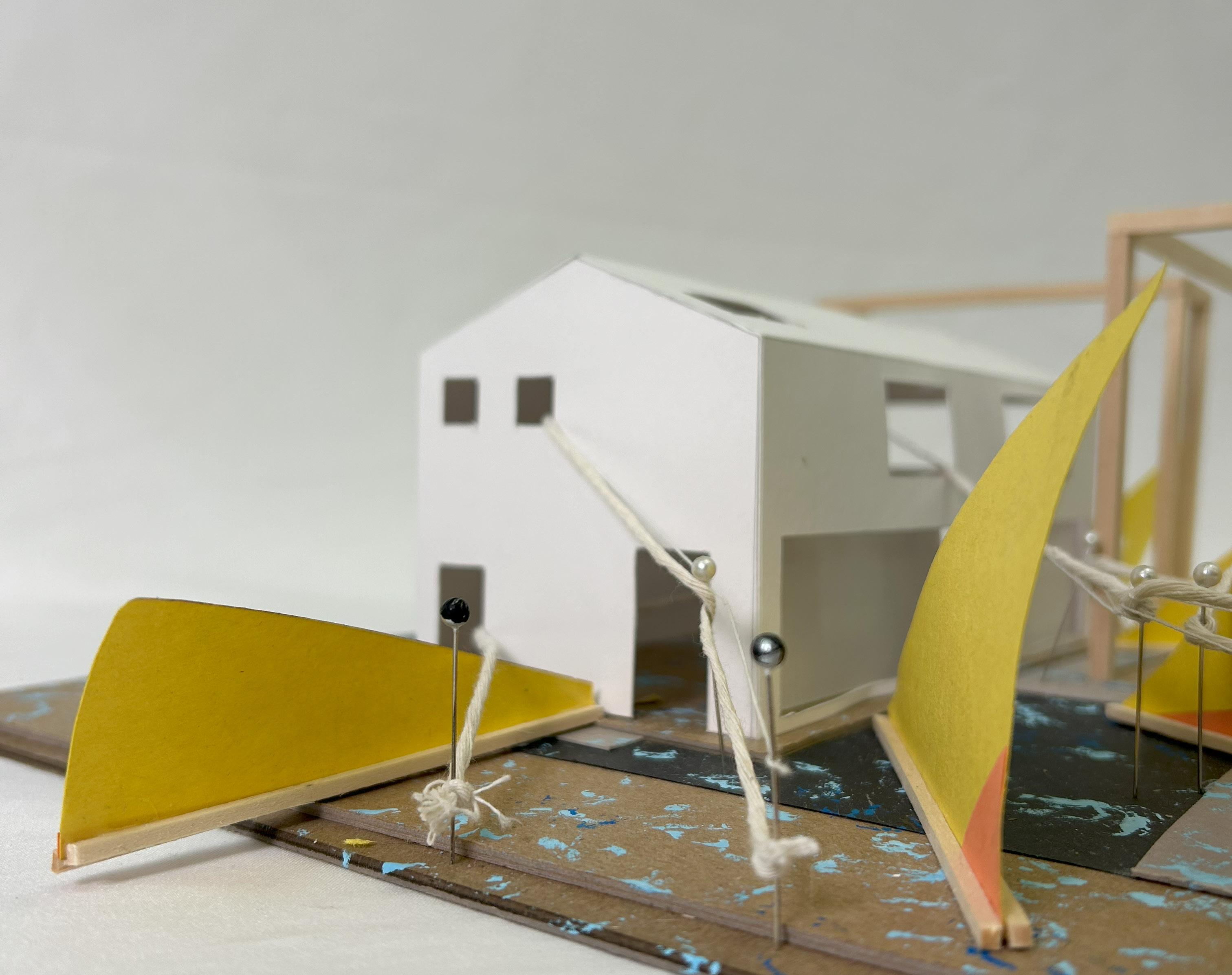
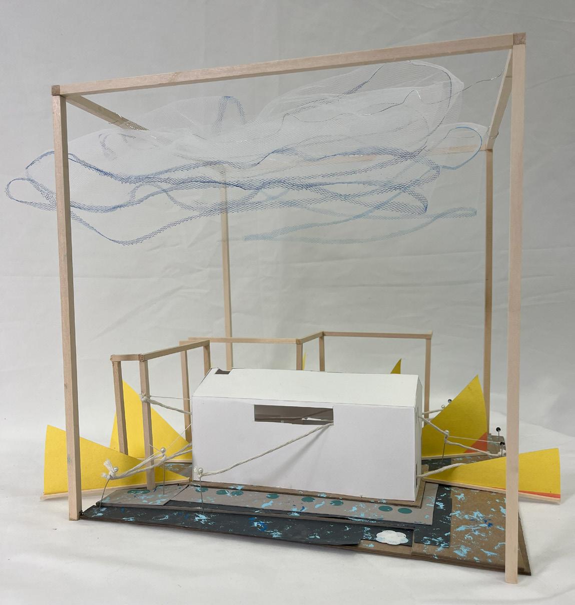
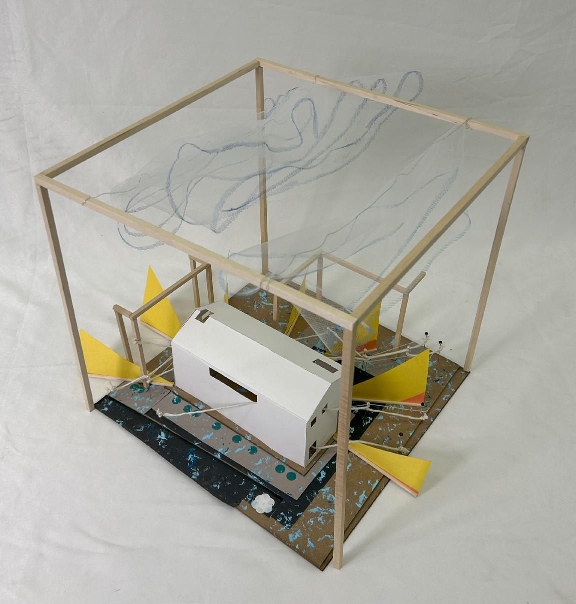
Part IV - Model Photos
This section of the project highlights our Site Analysis and Chunk Corner Assembly Model