10 XII December 2022 https://doi.org/10.22214/ijraset.2022.48468
ISSN: 2321-9653; IC Value: 45.98; SJ Impact Factor: 7.538 Volume 10 Issue XII Dec 2022- Available at www.ijraset.com

ISSN: 2321-9653; IC Value: 45.98; SJ Impact Factor: 7.538 Volume 10 Issue XII Dec 2022- Available at www.ijraset.com
Abhishek Wadde1, Dr. Uttam Awari2
1P.G. Student, Dept. of Civil Engineering, AISSMS College of Engineering, Pune, India 2 Prof. Dept. of Civil Engineering, AISSMS College of Engineering, Pune, India

Abstract: The advancement in construction field is increased day by day. The numbers of buildings, height of building is increased. The effect of lateral load is increased with respect to the increase of height. Advance construction methods and structural systems are to be introduced to enhance the structural safety. There are different types of structural systems which are to be used to resist the effect of lateral loads on the buildings. tube, bundled tube, tube in tube, and tube mega frame structures tubular structures. A tube-in-tube structure Comprises of a peripheral framed tube and a core tube interconnected by floor slabs. The frame tube structure takes more of lateral load the efficiency of this system is derived from the great number of rigid joints acting along the periphery, creating a large tube. In which the horizontal slabs and beams connecting vertical elements are assumed as continuous connecting medium having Equivalent distributed stiffness properties. The tube-in-tube structure with central tube provides stability against lateral loading as well as gravity loading. The Static analysis is use for analysis of tubular structures and the output of the models are evaluate to have a comparative study of their wind performance in different terrain, Also, this system provides enough opening for stairways, elevators and ducts etc. It is suitable for high rise structure. The use of tube-in-tube structure allows speedy construction. It is suitable for RCC, constructions. This study is focused on wind behavior of tube in tube structure for varying terrain category in India for the parameters like wind displacement, story drift, and time period.
Keywords: Tube in Tube Structure, Wind Loading, Terrain Category, Modal Mass Participations.
The advancement in construction field is increased day by day. The numbers of buildings, height of building is increased. The effect of lateral load is increased with respect to the increase of height. Modern construction methods and structural systems are to be introduced to enhance the structural safety. There are different types of structural systems which are to be used to resist the effect of lateral loads on the buildings. Rigid frame structures, braced frame structures, shear wall frame structures, outrigger systems, tubular structures are the different types of structural systems used in the buildings to enhance structural safety by reduce the effect of lateral loads on the buildings. The tubular systems are widely used and considered as a better structural system for tall buildings. There are different types of tubular structural systems which are given as framed tube, braced tube, bundled tube, tube in tube, and tube mega frame structures tubular structures. In recent years, tall buildings and structures have become slenderer, which increases the likelihood of excessive sway compared to older tall buildings. This creates additional difficulties for the engineering sector in resisting both lateral loads, such as wind and earthquake loads, and gravity loads. In the past, engineers primarily considered gravity loads when designing structures, but in recent years, due to the growth in height and seismic zone, they also consider lateral loads caused by wind and seismic forces. The height of tall structures is a comparative word. There is no globally applicable, precise definition for tall constructions. From a structural engineering standpoint, all tall structures must withstand both gravity and lateral loads. Due to the influx of a large population, towns and cities are expanding at a rapid rate. This phenomenon can be observed on every continent. The lack of available land for construction, especially in the world's biggest cities, is a widespread issue that has led to the vertical rather than horizontal development of structures. Today, high-rise commercial structures are symbols of modern society. These represent the strength of commerce in the current global economy. These also give the city a third dimension. Additionally, on a micro level, having a commercial space in a beautiful high-rise structure provides the firm with additional benefits in terms of increased client confidence and brand recognition. Globally, major towns and cities are constructing high-rise buildings with a very large number of stories, and India is not an exception to this trend. Tall structures comprised of a framework with multiple stories are flexible and vulnerable to the effect of wind forces.

ISSN: 2321-9653; IC Value: 45.98; SJ Impact Factor: 7.538 Volume 10 Issue XII Dec 2022- Available at www.ijraset.com
To resist the effect of lateral loads on the buildings, several structural systems must be employed. There are tube structures, rigid frame structures, braced frame structures, shear wall frame structures, outrigger systems, and braced frame structures. The tubular systems are widely employed and are regarded as the superior lateral structural solutions for high-rise buildings. The tubular constructions are subdivided into frame tube, braced tube, bundled tube, tube inside tube, and tube mega frame structures. Tube-intube structures and bundled tube structures are unique and novel tubular structure concepts. In towering buildings, tube-in-tube constructions will be increasingly utilized. In the subject of tubular constructions for tall buildings, bundled tube structures are the new concept. Nowadays, tubular constructions have become increasingly prevalent in tall buildings. Tube in tube structures is ideally suited for any tall structures. A tube-in- tube structure consists of a framed peripheral tube and a core tube that are joined by floor slabs. The overall structure resembles a large tube with a smaller tube in the centre. Both the inner and outer tubes share lateral loads. This paper includes an investigation of the vulnerability of different tubed structures to large wind loads when built as tubein- tube structures and bundled tube structures. Tube-in-tube structures and bundled tube structures are unique and novel tubular structure concepts. In this project, ETABS software was used to conduct a comparison of tube- in-tube structure and bundled tube structures. Using ETABS, the modelling and analysis are performed.
Since the wind varies over time, the wind spectrum and natural frequencies can be used to describe the difference in wind-related structural design of a typical high-rise building. In general, wind pressure and the resulting structural response are regarded as stationary random processes in which the time-averaged or mean component is separated from the fluctuating component. Tall buildings bluff bodies, and when wind blows against them, vortices are generated that result in an alternating force perpendicular to the direction of the wind. When the phenomena of vortex shedding occur along a substantial portion of the building's height, it can result in high forces and amplitudes. Wind loads linked with gustiness or turbulence produce substantially higher building responses than steady application of the same loads. Therefore, wind loads must be analysed as though they were inherently dynamic. The intensity of wind load depends on its rate of variation and the structure itself.
According to IS 875 part III, the Dynamic effects of wind loading are described as flexible thin structures and structural elements being evaluated to determine the wind- induced oscillations or excitations along and across the wind direction.
Based on the literature review presented in Chapter 2, the salient objectives of the Present study have been identified as follows The objectives of proposed work are as follows:
1) To study parametric design variables on the performance of a G+25 story building with different basic wind speed in terrain category III.
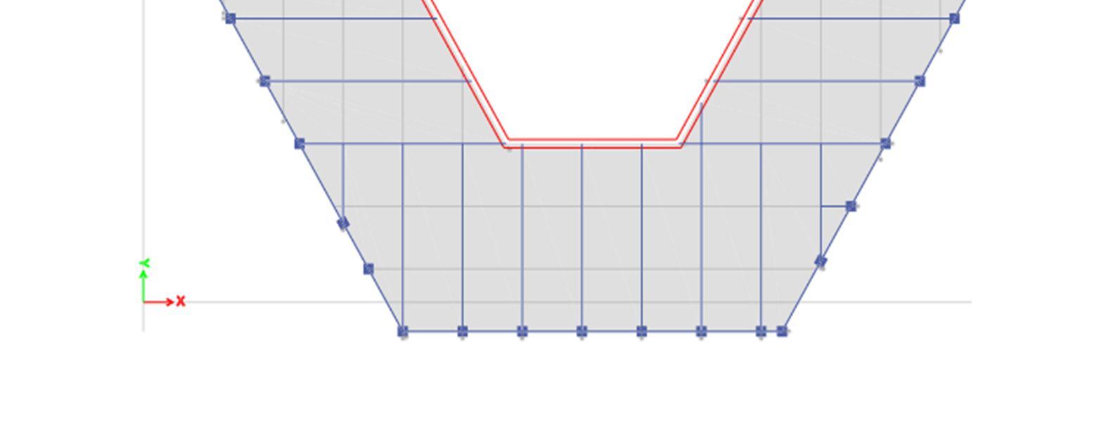
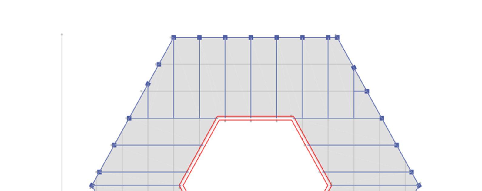
2) To study the behavior of the tube in tube RCC structure for dynamic analysis method using wind loads for different shapes i.e., square, rectangular and hexagonal etc.
3) Comparative analysis between tube in tube RCC structure with story open at different level.
4) To compare results between the models with respect to wind displacement and story drift.
The study will give more knowledge which result into benefits for future implementation with the help of RCC building actual design. To study the effect of shape on structural behavior.
Design Wind Pressure - The design wind pressure at any height above mean ground level shall be obtained by the following relationship between wind pressure and wind velocity The design wind pressure Pd can be obtained as,
Pd = Kd Ka. Kc. Pz where,
Kd = Wind directionality factor
Ka = Area averaging factor
Kc = Combination factor
Pz = 0.6 Vz 2
ISSN: 2321-9653; IC Value: 45.98; SJ Impact Factor: 7.538 Volume 10 Issue XII Dec 2022- Available at www.ijraset.com
where, Pz - design wind pressure in N/m2 at height Z
Vz - design wind velocity in m/s at height Z
Type of structure Frame structure
Moment-Resisting frame SMRF
Basic wind speed 39 &55 m/sec
No of Stories G+25
Height of each story 3m
Height of ground story 3m
Thickness of slab 125mm
Thickness of outer wall 150mm
Thickness of inner wall 100mm
Grade of reinforcing steel Fe 415 Density of concrete 25 kN/m3 Density of Brick wall 20 kN/m3
Grade of concrete in slab M30
Grade of concrete in beam M30
Grade of concrete in column M40 Analysis method Equivalent Statics Analysis
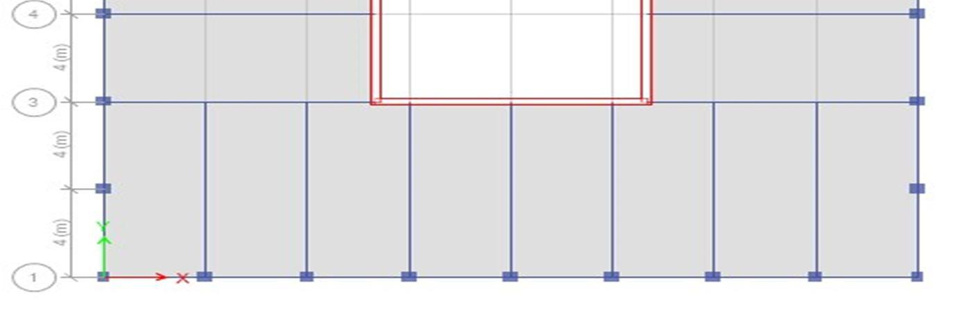
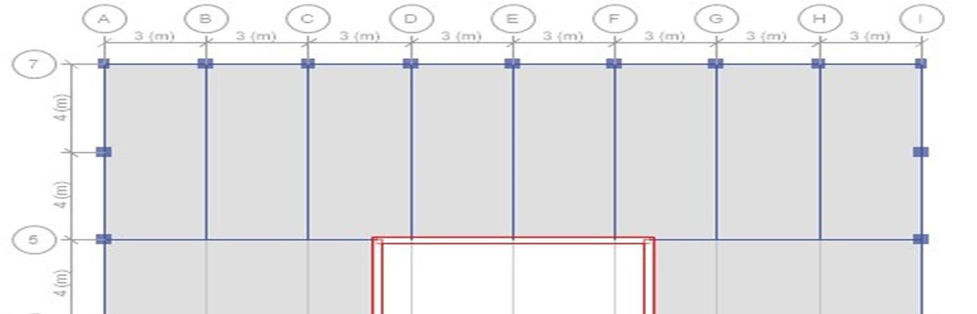
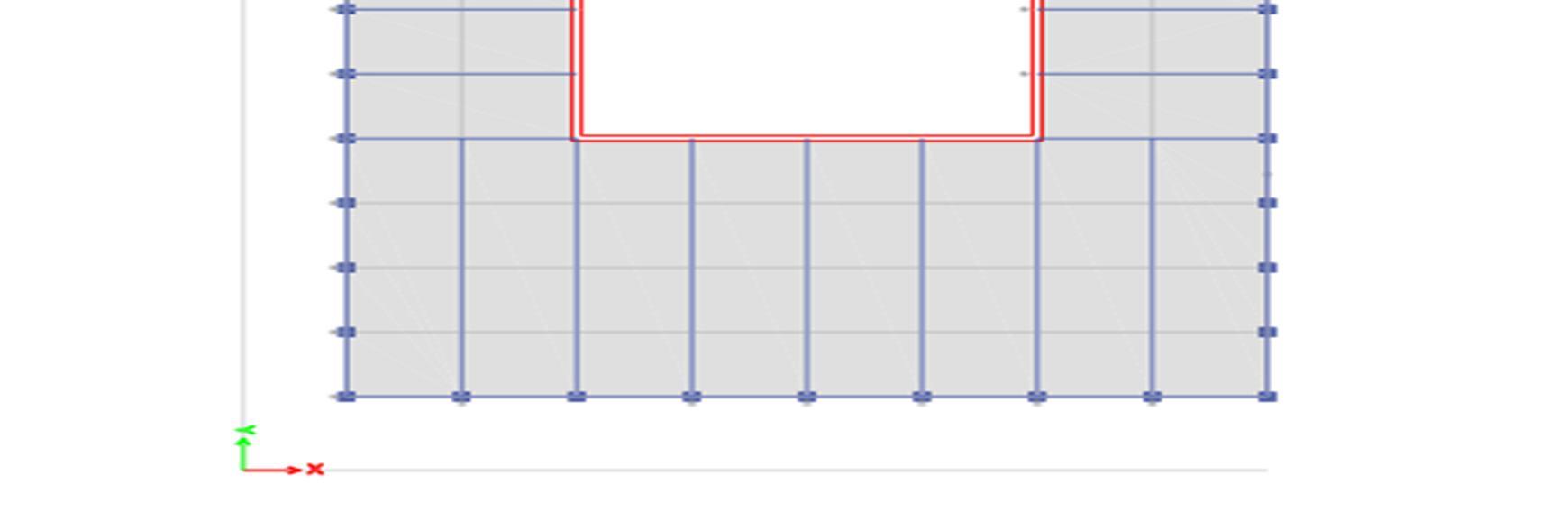
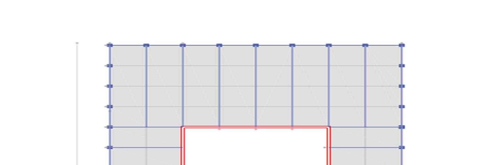
Multi-storied ferroconcrete, moment defying space frame are anatomized using professional software ETABS2016. Model G+24 of erecting frame withthree kudos in vertical andthree kudos in side direction is anatomized by Response spectrum method. The plan confines of structures are shown in table below. The plan view of structure, elevation of colorful frames is shown in numbers below.
A. Building Plan
1) Square shape plan
ISSN: 2321-9653; IC Value: 45.98; SJ Impact Factor: 7.538 Volume 10 Issue XII Dec 2022- Available at www.ijraset.com
ISSN: 2321-9653; IC Value: 45.98; SJ Impact Factor: 7.538 Volume 10 Issue XII Dec 2022- Available at www.ijraset.com

Table 1.1 General Building Displacement Results Basic Wind Speed 39 M/Sec. TABLE: Diaphragm Center of Mass Displacements Story Diaphragm Load Case/Combo UX UX UX mm mm mm
Story26 D1 WL+X 11.898 13.817 10.374
Story25 D1 WL+X 11.37 13.217 9.919
Story24 D1 WL+X 10.833 12.605 9.455
Story23 D1 WL+X 10.29 11.985 8.985
Story22 D1 WL+X 9.739 11.355 8.508
Story21 D1 WL+X 9.181 10.717 8.025
Story20 D1 WL+X 8.617 10.07 7.536
Story19 D1 WL+X 8.057 9.422 7.044
Story18 D1 WL+X 7.493 8.766 6.549
Story17 D1 WL+X 6.928 8.108 6.052
Story16 D1 WL+X 6.364 7.45 5.556
Story15 D1 WL+X 5.802 6.793 5.061
Story14 D1 WL+X 5.249 6.153 4.583
Story13 D1 WL+X 4.702 5.52 4.111
Story12 D1 WL+X 4.167 4.899 3.649
Story11 D1 WL+X 3.646 4.294 3.198
Story10 D1 WL+X 3.143 3.708 2.763
Story9 D1 WL+X 2.672 3.157 2.356 Story8 D1 WL+X 2.223 2.631 1.967
Story7 D1 WL+X 1.801 2.137 1.601
Story6 D1 WL+X 1.411 1.678 1.262
Story5 D1 WL+X 1.058 1.262 0.953
Story4 D1 WL+X 0.752 0.899 0.684
Story3 D1 WL+X 0.488 0.585 0.45
Story2 D1 WL+X 0.27 0.326 0.255 Story1 D1 WL+X 0.102 0.126 0.101 Graph 1.1 General Building
ISSN: 2321-9653; IC Value: 45.98; SJ Impact Factor: 7.538 Volume 10 Issue XII Dec 2022- Available at www.ijraset.com
Table 1 2 General building story drift results basic wind speed 39 m/sec TABLE: Story Drifts
Story Load Case/Combo Direction Drift Drift Drift m m m
Story26 WL+X X 0.000176 0.0002 0.000152
Story25 WL+X X 0.000179 0.000204 0.000155
Story24 WL+X X 0.000181 0.000207 0.000157
Story23 WL+X X 0.000184 0.00021 0.000159
Story22 WL+X X 0.000186 0.000213 0.000161
Story21 WL+X X 0.000188 0.000216 0.000163
Story20 WL+X X 0.000187 0.000216 0.000164
Story19 WL+X X 0.000188 0.000218 0.000165
Story18 WL+X X 0.000188 0.000219 0.000166
Story17 WL+X X 0.000188 0.00022 0.000166
Story16 WL+X X 0.000187 0.000219 0.000165
Story15 WL+X X 0.000185 0.000213 0.00016
Story14 WL+X X 0.000182 0.000211 0.000157
Story13 WL+X X 0.000178 0.000207 0.000154
Story12 WL+X X 0.000174 0.000202 0.00015
Story11 WL+X X 0.000168 0.000195 0.000145
Story10 WL+X X 0.000157 0.000184 0.000136
Story9 WL+X X 0.00015 0.000175 0.00013
Story8 WL+X X 0.000141 0.000165 0.000122
Story7 WL+X X 0.00013 0.000153 0.000113
Story6 WL+X X 0.000118 0.000139 0.000103
Story5 WL+X X 0.000102 0.000121 0.00009
Story4 WL+X X 0.000088 0.000105 0.000078
Story3 WL+X X 0.000073 0.000086 0.000065
Story2 WL+X X 0.000056 0.000067 0.000051
Story1 WL+X X 0.000034 0.000042 0.000034
Story Drift Square Rectangular Hexagonal
ISSN: 2321-9653; IC Value: 45.98; SJ Impact Factor: 7.538 Volume 10 Issue XII Dec 2022- Available at www.ijraset.com
Table 5.3 wind displacement in bracing system in 39m/sec basic wind speed
TABLE: Diaphragm Center of Mass Displacements
Story Diaphragm Load Case/Combo UX UX UX mm mm mm
Story26 D1 WL+X 9.903 11.954 8.889
Story25 D1 WL+X 9.488 11.459 8.518
Story24 D1 WL+X 9.064 10.953 8.137
Story23 D1 WL+X 8.632 10.437 7.75
Story22 D1 WL+X 8.193 9.912 7.356
Story21 D1 WL+X 7.746 9.378 6.956
Story20 D1 WL+X 7.291 8.833 6.548
Story19 D1 WL+X 6.836 8.284 6.137
Story18 D1 WL+X 6.375 7.727 5.721
Story17 D1 WL+X 5.912 7.165 5.301
Story16 D1 WL+X 5.447 6.6 4.881
Story15 D1 WL+X 4.981 6.034 4.46
Story14 D1 WL+X 4.519 5.478 4.05
Story13 D1 WL+X 4.062 4.928 3.643
Story12 D1 WL+X 3.611 4.385 3.243
Story11 D1 WL+X 3.17 3.853 2.851 Story10 D1 WL+X 2.742 3.337 2.472
Story9 D1 WL+X 2.338 2.848 2.113
Story8 D1 WL+X 1.951 2.38 1.77
Story7 D1 WL+X 1.587 1.937 1.446
Story6 D1 WL+X 1.247 1.525 1.143 Story5 D1 WL+X 0.938 1.149 0.866
Story4 D1 WL+X 0.669 0.818 0.623
Story3 D1 WL+X 0.435 0.532 0.411 Story2 D1 WL+X 0.241 0.295 0.233 Story1 D1 WL+X 0.092 0.112 0.092
ISSN: 2321-9653; IC Value: 45.98; SJ Impact Factor: 7.538 Volume 10 Issue XII Dec 2022- Available at www.ijraset.com
Table 5.4 story drift at bracing system in 39 m/sec basic wind speed
TABLE: Story Drifts
Story Load Case/Combo Direction Drift Drift Drift m m m
Story26 WL+X X 0.000138 0.000165 0.000124
Story25 WL+X X 0.000141 0.000169 0.000127
Story24 WL+X X 0.000144 0.000172 0.000129
Story23 WL+X X 0.000146 0.000175 0.000131
Story22 WL+X X 0.000149 0.000178 0.000134
Story21 WL+X X 0.000152 0.000181 0.000136
Story20 WL+X X 0.000152 0.000183 0.000138
Story19 WL+X X 0.000153 0.000186 0.000139
Story18 WL+X X 0.000154 0.000187 0.00014
Story17 WL+X X 0.000155 0.000188 0.000141
Story16 WL+X X 0.000155 0.000189 0.000141
Story15 WL+X X 0.000154 0.000185 0.000137
Story14 WL+X X 0.000153 0.000184 0.000136
Story13 WL+X X 0.00015 0.000181 0.000134
Story12 WL+X X 0.000147 0.000177 0.000131
Story11 WL+X X 0.000143 0.000172 0.000127
Story10 WL+X X 0.000135 0.000163 0.00012
Story9 WL+X X 0.000129 0.000156 0.000114
Story8 WL+X X 0.000122 0.000147 0.000108
Story7 WL+X X 0.000113 0.000137 0.000101
Story6 WL+X X 0.000103 0.000125 0.000093
Story5 WL+X X 0.00009 0.00011 0.000081
Story4 WL+X X 0.000078 0.000095 0.000071
Story3 WL+X X 0.000065 0.000079 0.00006 Story2 WL+X X 0.00005 0.000061 0.000047 Story1 WL+X X 0.000031 0.000037 0.000031
Story Drift
Graph 5.4 story drift in bracing vs. different shape of structure 0 0.00002 0.00004 0.00006 0.00008 0.0001 0.00012 0.00014 0.00016 0.00018 0.0002 1
Square Rectangular Hexagonal
ISSN: 2321-9653; IC Value: 45.98; SJ Impact Factor: 7.538 Volume 10 Issue XII Dec 2022- Available at www.ijraset.com
Table 1.5 Displacement Results in Open Story In 39 M/Sec Basic Wind Speed
TABLE: Diaphragm Center of Mass Displacements Story Diaphragm Load Case/Combo UX UX UX mm mm mm
Story26 D1 WL+X 5.068 4.904 5.53
Story25 D1 WL+X 4.847 4.695 5.292
Story24 D1 WL+X 4.621 4.481 5.048
Story23 D1 WL+X 4.391 4.263 4.799
Story22 D1 WL+X 4.158 4.04 4.546
Story21 D1 WL+X 3.92 3.814 4.289
Story20 D1 WL+X 3.682 3.586 4.031
Story19 D1 WL+X 3.445 3.358 3.771
Story18 D1 WL+X 3.205 3.125 3.507
Story17 D1 WL+X 2.964 2.891 3.242
Story16 D1 WL+X 2.722 2.656 2.976
Story15 D1 WL+X 2.483 2.423 2.713
Story14 D1 WL+X 2.247 2.196 2.458 Story13 D1 WL+X 2.014 1.971 2.206
Story12 D1 WL+X 1.784 1.749 1.958
Story11 D1 WL+X 1.561 1.532 1.715
Story10 D1 WL+X 1.346 1.324 1.483 Story9 D1 WL+X 1.144 1.127 1.265 Story8 D1 WL+X 0.952 0.939 1.057 Story7 D1 WL+X 0.771 0.762 0.86
Story6 D1 WL+X 0.603 0.598 0.677 Story5 D1 WL+X 0.452 0.449 0.512
Story4 D1 WL+X 0.321 0.32 0.368 Story3 D1 WL+X 0.208 0.208 0.243 Story2 D1 WL+X 0.115 0.115 0.137 Story1 D1 WL+X 0.043 0.044 0.054 Graph 5.5 open story building displacement in 39m/sec displacement
ISSN: 2321-9653; IC Value: 45.98; SJ Impact Factor: 7.538
Volume 10 Issue XII Dec 2022- Available at www.ijraset.com
Table 5.6 open story drift vs. different shape of structure in 39m/sec
TABLE: Story Drifts
Story Load Case/Combo Direction Drift Drift Drift m m m
Story26 WL+X X 0.000074 0.00007 0.000079
Story25 WL+X X 0.000075 0.000071 0.000081
Story24 WL+X X 0.000077 0.000073 0.000083
Story23 WL+X X 0.000078 0.000074 0.000084
Story22 WL+X X 0.000079 0.000075 0.000086
Story21 WL+X X 0.000079 0.000076 0.000086
Story20 WL+X X 0.000079 0.000076 0.000087
Story19 WL+X X 0.00008 0.000077 0.000088
Story18 WL+X X 0.00008 0.000078 0.000089
Story17 WL+X X 0.00008 0.000078 0.000089
Story16 WL+X X 0.00008 0.000078 0.000088
Story15 WL+X X 0.000079 0.000076 0.000085
Story14 WL+X X 0.000078 0.000075 0.000084
Story13 WL+X X 0.000076 0.000074 0.000083
Story12 WL+X X 0.000075 0.000072 0.000081
Story11 WL+X X 0.000072 0.000069 0.000077
Story10 WL+X X 0.000067 0.000066 0.000073
Story9 WL+X X 0.000064 0.000063 0.00007 Story8 WL+X X 0.00006 0.000059 0.000066
Story7 WL+X X 0.000056 0.000055 0.000061 Story6 WL+X X 0.00005 0.000049 0.000055
Story5 WL+X X 0.000044 0.000043 0.000048 Story4 WL+X X 0.000038 0.000037 0.000042 Story3 WL+X X 0.000031 0.000031 0.000035 Story2 WL+X X 0.000024 0.000024 0.000028 Story1 WL+X X 0.000014 0.000015 0.000018
Graph 5.6 open story, story drift vs. different shape of building in 39m/sec basic wind speed 0 0.00001 0.00002 0.00003 0.00004 0.00005 0.00006 0.00007 0.00008 0.00009 0.0001 1 2 3 4 5 6 7 8 9 10 11 12 13 14 15 16 17 18 19 20 21 22 23 24 25 26
Story Drift
Square Rectangular Hexagonal
ISSN: 2321-9653; IC Value: 45.98; SJ Impact Factor: 7.538 Volume 10 Issue XII Dec 2022- Available at www.ijraset.com
A. Analysis of RCC tube in tube structure with different basic wind speed i.e., 39m/sec, and 55m/sec with medium soil condition at zone III has been done and significant variations in square building has been noted as compared to rectangular and hexagonal building.
B. Results indicate that same all value similar to tube in tube with open story, because of earthquake zone are same for both type of building.
C. Analysis of RCC tube in tube structure and tube in tube with open story structure in zone III with medium soil but overall performance of tube in tube with open story structure is healthier than remaining all structure.
D. Comparing the displacement in tube in tube structure and tube in tube with open story structure almost both displacement results are same, but the wind displacement is increased as compare to 39m/sec basic wind speed but relatively shows good performance in time ages.
E. The story drift in tube in tube structure and tube in tube with open story structure both structures are 4 to 4.5 % drift are available so structure behaviour are nonlinear. And also, in different shape structure 3 to 3.7 % drift are available, so structure is show linear behaviour.
F. Also, Analysis of RCC different shape of tube in tube structure i.e. rectangular, Square and Hexagonal shape structure in basic wind speed 39m/sec with 55m/sec in medium soil but overall performance of square shape of structure is healthier than remining all shape of structure.
[1] Analysis Of RCC Tube in Tube Structure with Different Basic Wind Speed I.E., 39m/Sec, and 55m/Sec with Medium Soil Condition at Zone III Has Been Done.
[2] Results Indicate That Same All Value Similar to Tube in Tube with Open Story, Because Of Earthquake Zone Are Same for Both Type of Building.
[3] Analysis Of RCC Tube In Tube Structure And Tube In Tube With Open Story Structure In Zone III With Medium Soil But Overall Performance Of Tube In Tube With Open Story Structure Is Healthier Than Remaining All Structure.
[4] Comparing The Wind Displacement In Tube In Tube Structure And Tube In Tube With Open Story Structure, In Wind Displacement Increased As Compare To 39m/Sec Basic Wind Speed But Relatively Shows Good Performance In Time Ages.
[5] The Story Drift In Tube In Tube Structure And Tube In Tube With Open Story Structure Both Structures Are 4 To 4.5 % Drift Are Available So Structure Behaviour Are Nonlinear. And Also, In Different Shape Structure 3 To 3.7 % Drift Are Available, So Structure Is Show Linear Behaviour.
[6] Also, Analysis of RCC Different Shape of Tube in Tube Structure I.E. Rectangular, Square and Hexagonal Shape Structure in Basic Wind Speed 39m/Sec With 55m/Sec in Medium Soil but Overall Performance of Square Shape of Structure Is Healthier Than Remining All Shape of Structure.
[7] Imposed Loads”, Bureau of Indian Standards, New Delhi, 1987. IS 456, “Indian Standard Code of Practice for Plain and Reinforced Concrete”, Bureau of Indian Standards, New Delhi, 2000. IS 1893 (Part I), “Criteria For Earthquake Resistant Design Of Structures”, Bureau Of Indian Standards, New Delhi, 2002.