
10 X October 2022 https://doi.org/10.22214/ijraset.2022.47066
ISSN: 2321 9653; IC Value: 45.98; SJ Impact Factor: 7.538

Volume 10 Issue X Oct 2022 Available at www.ijraset.com

ISSN: 2321 9653; IC Value: 45.98; SJ Impact Factor: 7.538
Volume 10 Issue X Oct 2022 Available at www.ijraset.com
Abstract: The Idea is to make an Automated Vehicle Escape Mechanism or a Vehicle Escape device which would help the Passengers of the Car to get out in case of Certain Accidental Situations such as Drowning of Car and Car flipped Upside Down. Mechanism or a device used for breaking of window. Due to which person or people can be able to get out of car through window or windshield. In the case of drowning of car, window or glass which is not under water can be detected and breaks for getting out of car at the right time. The device is automatic as well as manual switch. Different types of sensors are involved for different situation scenarios.
Typically, modern windshields are created from laminated safety glass, which is a treated glass and usually combines two curved glass sheets and a plastic lamina ted layer between for safety. They are then bonded to the window frame. Whereas, windshields for motorbikes are commonly created with high impact acrylic plastic or poly carbonate. Auto glass is either tempered or laminated. The glass usually used for the front and rear door windows and the rear window are made from tempered glass, the windshield is made from laminated glass.
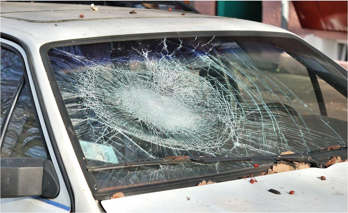
Laminated glass will break but it will not fly into shards during a collision. The glass is designed to take heavy impact without shattering. This eliminates the possibility of passengers being injured by flying glass. In the event the occupant in the car is thrown into the window, the laminated glass acts somewhat like a cushion. Although laminated glass is used extensively in the auto industry, it can be used for any application where there is the possibility of impact by a person.
Although it is possible for the door windows and the rear window of a car to be produced from laminated glass, there is not the same potential for human impact in the event of a crash. Therefore, the majority of these windows are made from tempered glass.it does not shatter into dangerous shards but rather into thousands of harmless pebble like pieces that do not have sharp edges.

Breaking the glass will be relatively easy. There is a catch, though. If you use heavy metal to break a glass, you should go around the edge of the glass at it is the weakest point. Manufacturers assume that in a collision or impact, the centre of the windshield or auto glass is the most vulnerable point. Therefore, they reinforce the glass in the middle. The surface is at weakest on the edges where the glass is most likely to chip, crack or break. You can start there and slowly work your way to the centre where the entire piece will eventually shatter.
ISSN: 2321 9653; IC Value: 45.98; SJ Impact Factor: 7.538

Volume 10 Issue X Oct 2022 Available at www.ijraset.com
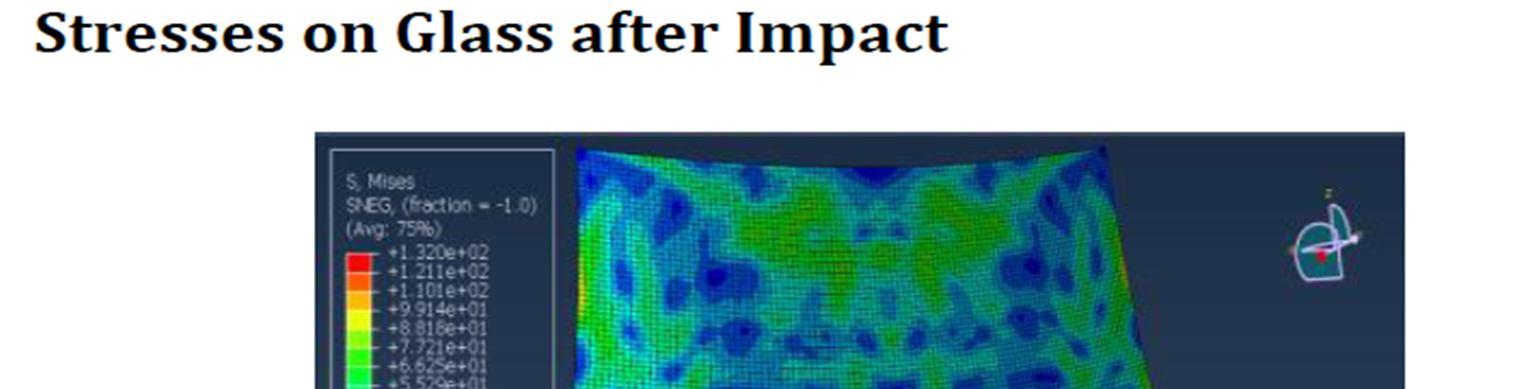
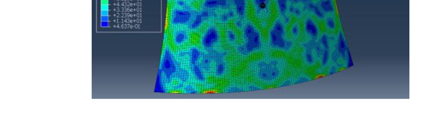
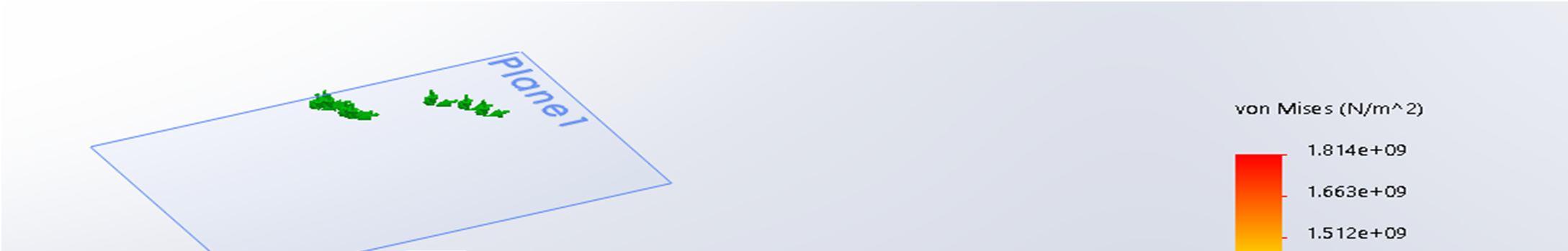
The spherical is considered as the object of impact which has a mass of 100g and the velocity of the object is of 27.77m/s. The object has been constrained in X and Z directions. And the velocity boundary conditions are given in Y direction. The fig above shows stress impact of the object on the glass, as we compare (glass before impact of the object) can see the stress distribution through the glass and it is found at the edges of the glass.
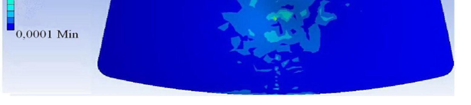
The diagram of the maximum stress under the impact force in the centre of the glass.
So that’s why windshield is toughened at the center to protect from impact of force. hence glass is weaker at edges. It can easily brake at edges by applying
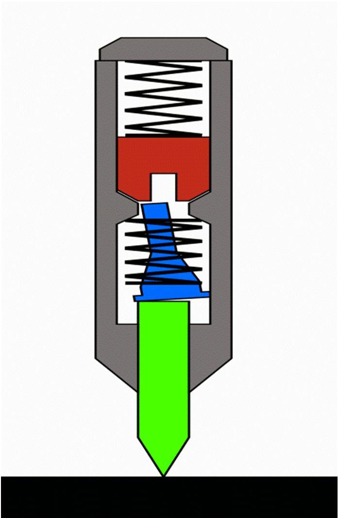
The most common mechanism is based upon the Sweet patent. Within the body of the punch, there are three principal moving parts arranged in line:
1) The punch
2) The intermediate rod (tumbler)
3) The hammer (hammer mass)
The hammer mass is spring loaded from the back of the punch by a large spring. (The spring's preload compression can usually be adjusted by loosening or tightening the end cap at the back most portion of the punch, to decrease or increase the force of the punch.) A stopped hole drilled in the front center portion of the hammer mass facing the tumbler acts as a receiver for the rod, and as an anvil for the punch action.
ISSN: 2321 9653; IC Value: 45.98; SJ Impact Factor: 7.538 Volume 10 Issue X Oct 2022 Available at www.ijraset.com
The tumbler provides the automation. When reset, a provision is made such that the tumbler rod is cocked slightly, so that its resting position is skewed and the tip contacts the hammer mass on the face of the hammer slightly offset to the hole. This is commonly done by using a special bent end on the tumbler spring[17] or using an out of flat face on the bottom end of the pin or top of the punch.[18] It bears on the hammer mass and pushes it back against its spring as the punch is pressed, storing energy in the hammer spring.
As the punch is further pressed against the workpiece, the tumbler travels back until the point where its tapered midsection begins contacting the surface of the guide hole in the body of the punch. As it continues back, it is pushed into alignment with the centre axis of the tool. When the tip of the tumbler is nearly centered, it slips into the receiving hole in the hammer mass, and releases the hammer. The hammer mass is then allowed to move forward, propelled by the rear spring. Because the hole in the hammer mass does not go through the mass and is less deep than the end section of the tumbler, the tip of the tumbler bottoms out in the hole in the hammer, and the impulse of the hammer mass is transmitted through the tumbler, through the punch, and to the workpiece.
The electric doorbell is a simple circuit that triggers a sound on the completion of circuit by pressing the button. It is this simplicity that makes doorbell such a marvel. The simple devices in the doorbell put the scientific principle of electromagnetism into action in a useful way. In order to understand the operations of an electric bell, you should first need to understand what is anelectromagnet Well, to put it in simple words, an electromagnet is basically a type of magnet in which the magnetic field is produced with the help of an electric current. When any electrical influences electromagnet it works as a standard magnet (generating magnetic fields). When the power generation to an electromagnet stops, the production of the magnetic field also stops. So, in an electric bell, an electromagnet forms an important part along with Armature, Spring, Armature rod, Hammer and a Gong. An electric source, for example, a battery can be used to power the electromagnet used in an electric bell. The electric circuit is completed by installing a push switch which you can press to generate sound in an electric bell. The switch also acts as the circuit breaker. So once the setup is completed, when the switch is pressed, the circuit loop is complete which causes the current to flow through the circuit. The arm which strikes the gong is connected to spring at one end and an iron ball at the other end. This is called a hammer or a striker. The arm is attached to an iron strip which is attracted to the electromagnet when the circuit is complete and the current flowing through it Why does this happen? It’s mainly because the magnetic field created by the electromagnet attracts the iron strip towards it when the circuit is complete. This is the moment when you hear the ringing sound since the hammer keeps hitting the gong. Meanwhile, at its rest position, the hammer is held away from the gong on account of the spring attached to its arm. This is an anchored arm.
ISSN: 2321 9653; IC Value: 45.98; SJ Impact Factor: 7.538
Volume 10 Issue X Oct 2022 Available at www.ijraset.com
Now that you have an understanding of the important parts in an electric bell, the step by step process of the working of the electric bell is described below:
a) The switch is pressed and current flows through the circuit.
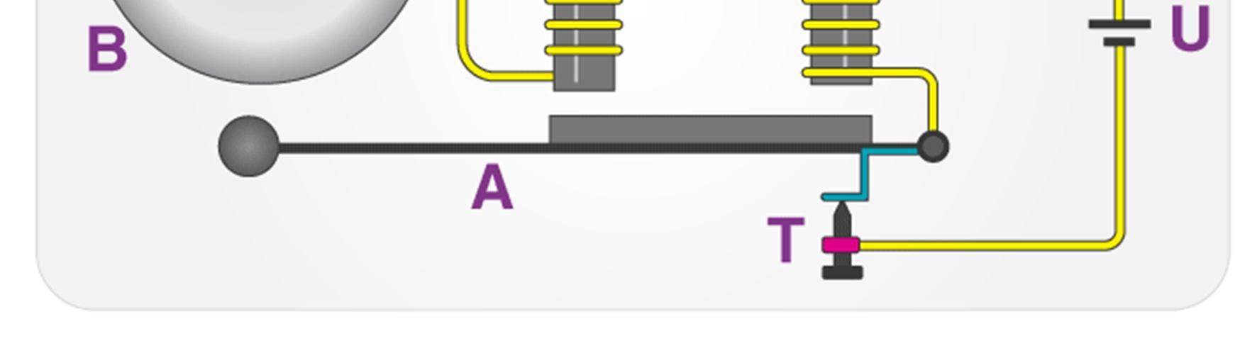
b) The electromagnet is powered and generates a magnetic field that attracts the iron strip towards it.
c) The striker strikes the gong (bell).
d) When the striking arm strikes the gong, the contact is broken and current stops flowing through the circuit.
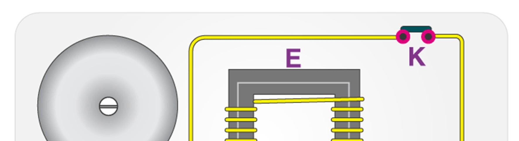
e) This causes the electromagnet to lose its magnetic field.
f) The connected spring arm returns the striker to its original rest position.
g) The contact is restored and current flows through the circuit (provided the main switch is still pressed).
h) The process is repeated from the beginning.
1) Glass Breaking Tool
• Spring, Force Generating Device (such as Hydraulic Actuator) and a Release Mechanism that releases the Stored Energy in the Spring.(Same as Automatic Centre Punch)
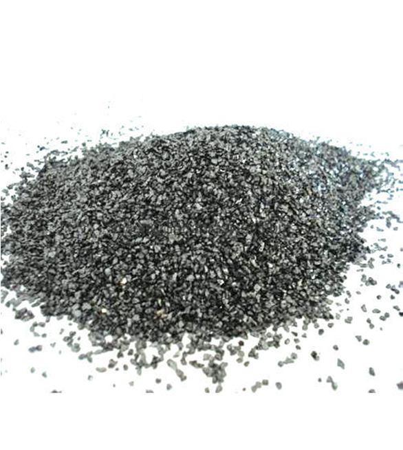
• Aluminium Oxide to make the Tip of the Tool (its hardness makes it suitable for use as an abrasive and as a component in cutting tools.)
Lies just below Diamond in Hardness on Mohs Scale of mineral Hardness
ISSN: 2321 9653; IC Value: 45.98; SJ Impact Factor: 7.538 Volume 10 Issue X Oct 2022 Available at www.ijraset.com
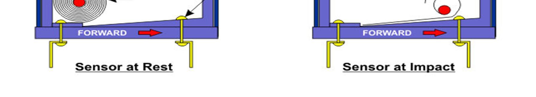
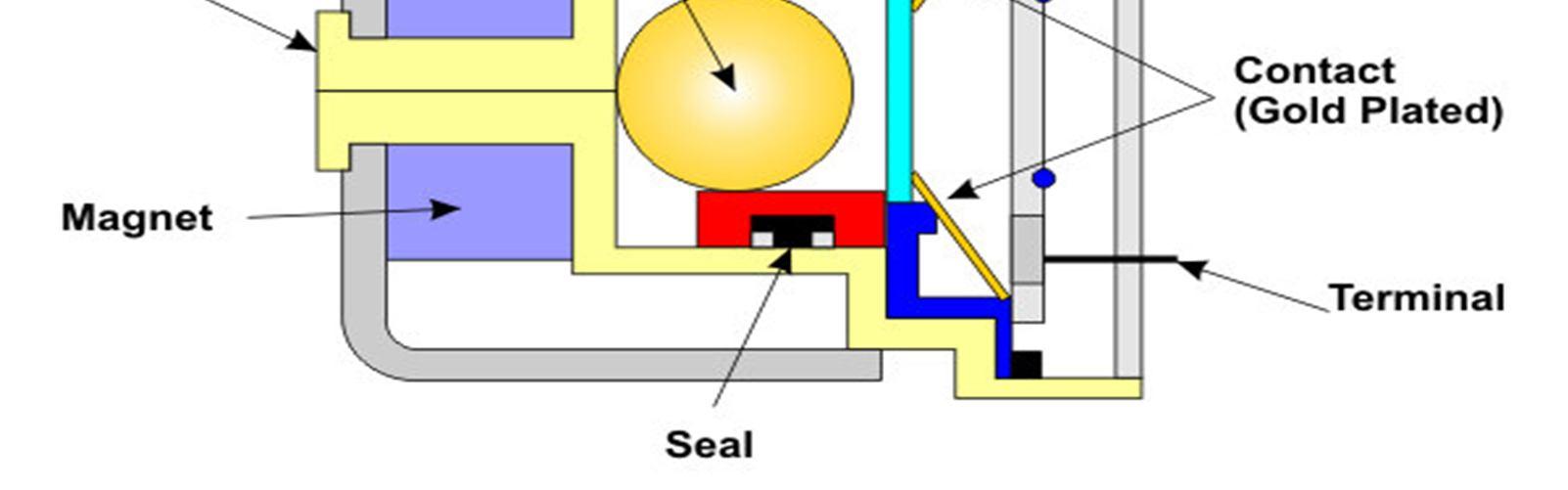
An impact sensor is normally fitted to the front of the vehicle as this is where a collision is likely to occur. The sensor is positioned inside the engine and a similar safety sensor is located inside the passenger zone of the vehicle. This safety sensor is required to measure the intensity of the collision to determine whether the impact is over a certain threshold to justify the release of an airbag. Both types of sensors (termed inertia sensors) work on the principle of detecting a decrease in acceleration of a moving vehicle and generating an electrical impulse. Figure 1 is a schematic diagram of an inertial sensor.
During a collision with another moving vehicle, the sensing mass is forced forward into the gold plated contacts as a result of the change in the state of motion. Following the movement of this metal ball into the contacts, this metal mass makes contact with electrical terminals at either side of the metal ball which alerts the central unit of a collision (i.e. the electrical contact completes the circuit).
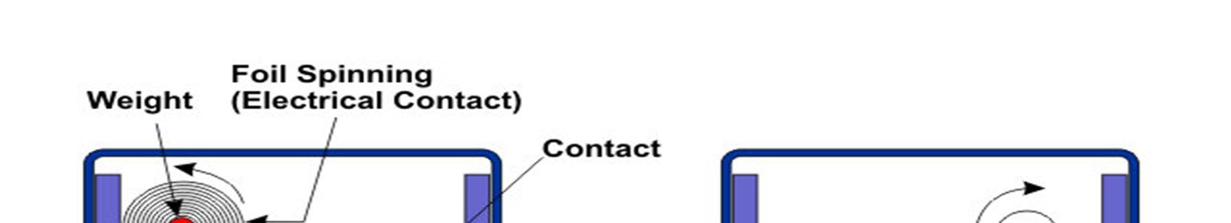
The roller type sensor consists of a weight connected to a coil spring component. Like the mass type sensor, during impact with an oncoming vehicle, the metal weight is forced forward which alters the tension on the coil spring to manipulate the electrical circuit that closes off the sensor contact. It is important to note that the impact and safety sensors must activate and close off at the same time to allow for the deployment of the airbag (figure 2).

ISSN: 2321 9653; IC Value: 45.98; SJ Impact Factor: 7.538
Volume 10 Issue X Oct 2022 Available at www.ijraset.com
Micro electro mechanical Systems (MEMS) Technology is one of the most advanced technologies that have been applied in the making of most of the modern devices like video projectors, bi analysis chips and also car crash airbag sensors. This concept was first explainedS by Professor R. Howe in the year 1989. Since then many prototypes have been released and revised and has thus become an integral part of the latest mechanical products available in the market today.
During its early stage, the MEMS chip had two parts. One part included the main structure of the chip and the other part included everything needed for signal conditioning. This method was not successful as the total space taken by the device was larger, and thus the different parts of a single chip needed multi assembling procedures. The output obtained from such a device had less accuracy and the mounting of such a device was difficult.
As the technology became more advanced the idea of integrating multi chips was applied on to produce a single chip MEMS with high performance and accuracy. The main idea behind this technology is to use some of the basic mechanical devices like cantilevers and membranes to have the same qualities of electronic circuits. To obtain such a concept, micro fabrication process must be carried out. Though an electronic process is carried out, an MEMS device cannot be called as an electronic circuit. MEMS duplicate a mechanical part and have holes, cantilevers, membranes, channels, and so on. But an electronic circuit has a firm and compact structure. To make MEMS from silicon process, the manufacturer must have a deep knowledge in electronics, mechanical and also about the materials used for the process.
a) MEMS devices are very small and can be applicable for many mechanical purposes where large measurements are needed.
b) The small size of the device has also helped in reducing its cost.
c) If two or three different devices are needed to deploy a particular process, all of them can be easily integrated in an MEMS chip with the help of microelectronics. Thus, data reception, filtering, storing, transfer, interfacing, and all other processes can be carried out with a single chip.
a) The device is highly applicable as an accelerometer, and thus can be deployed as airbag sensors or in digital cameras in order to stabilize the image.
b) Can be used as a pressure sensor so as to calculate the pressure difference in blood, manifold pressure (MAP), and also tire pressure.
c) It is commonly used in a gyroscope, DNA chips and also inkjet printer nozzle.
d) Optical MEMS is used for making projectors, optical fiber switch and so on.
e) RFMEMS is used for making antennas, filters, switches, relays, RAM’s microphones, microphones, and so on.
An accelerometer is an electromechanical device that is used to measure acceleration and the force producing it. Many types of accelerometers are available in the market today. They can be divided according to the force (static or dynamic) that is to be measured. Even today, one of the most commonly used one is the piezoelectric accelerometer. But, since they are bulky and cannot be used for all operations, a smaller and highly functional device like the MEMS accelerometer was developed. Though the first of its kind was developed 25 years ago, it was not accepted until lately, when there was need for large volume industrial applications. Due to its small size and robust sensing feature, they are further developed to obtain multi axis sensing.
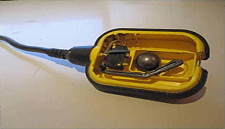
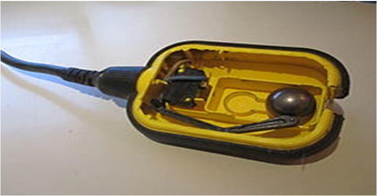
A float switch is a type of level sensor, a device used to detect the level of liquid within a tank. The switch may be used to control a pump, as an indicator, an alarm, or to control other devices. One type of float switch uses a mercury switch inside a hinged float. Another common type is a float that raises a rod to actuate a microswitch. One pattern uses a reed switch mounted in a tube; a float, containing a magnet, surrounds the tube and is guided by it. When the float raises the magnet to the reed switch, it closes. Several reeds can be mounted in the tube for different level indications by one assembly.
ISSN: 2321 9653; IC Value: 45.98; SJ Impact Factor: 7.538 Volume 10 Issue X Oct 2022 Available at www.ijraset.com
A very common application is in sump pumps and condensate pumps where the switch detects the rising level of liquid in the sump or tank and energizes an electrical pump which then pumps liquid out until the level of the liquid has been substantially reduced, at which point the pump is switched off again. Float switches are often adjustable and can include substantial hysteresis. That is, the switch's "turn on" point may be much higher than the "shut off" point. This minimizes the on off cycling of the associated pump.Some float switches contain a two stage switch. As liquid rises to the trigger point of the first stage, the associated pump is activated. If the liquid continues to rise (perhaps because the pump has failed or its discharge is blocked), the second stage will be triggered. This stage may switch off the source of the liquid being pumped, trigger an alarm, or bothA sump pump with a float switch. Where level must be sensed inside a pressurized vessel, often a magnet is used to couple the motion of the float to a switch located outside the pressurized volume. In some cases, a rod through a stuffing box can be used to operate a switch, but this creates high drag and has a potential for leakage. Successful float switch installations minimize the opportunity for accumulation of dirt on the float that would impede its motion. Float switch materials are selected to resist the deleterious effects of corrosive process liquids. In some systems, a properly selected and sized float can be used to sense the interface level between two liquids of different density.
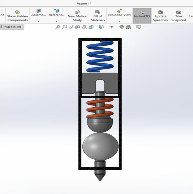
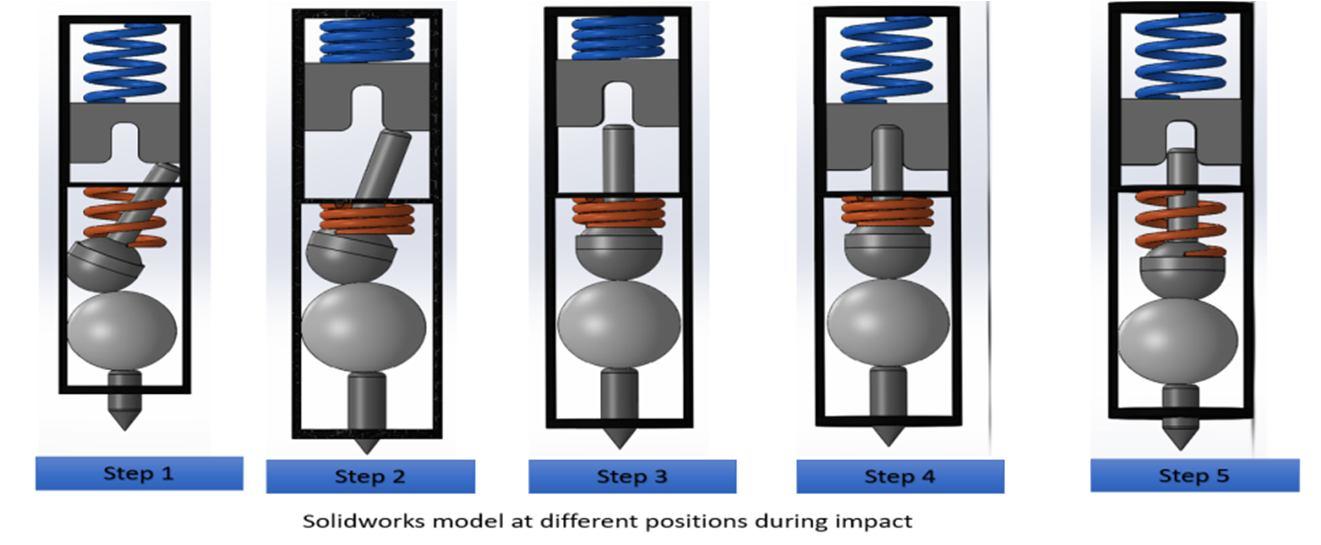
Solidworks Model
ISSN: 2321 9653; IC Value: 45.98; SJ Impact Factor: 7.538
Volume 10 Issue X Oct 2022 Available at www.ijraset.com
Within the body of the punch, there are three principal moving parts arranged in line:
a) The punch
b) The intermediate rod (tumbler)
c) The hammer (hammer mass)
The hammer mass is spring loaded from the back of the punch by a large spring. (The spring's preload compression can usually be adjusted by loosening or tightening the end cap at the back most portion of the punch, to decrease or increase the force of the punch.) A stopped hole drilled in the front center portion of the hammer mass facing the tumbler acts as a receiver for the rod, and as an anvil for the punch action. The tumbler provides the automation. When reset, a provision is made such that the tumbler rod is cocked slightly, so that its resting position is skewed and the tip contacts the hammer mass on the face of the hammer slightly offset to the hole. This is commonly done by using a special bent end on the tumbler spring or using an out of flat face on the bottom end of the pin or top of the punch. It bears on the hammer mass and pushes it back against its spring as the punch is pressed, storing energy in the hammer spring. As the punch is further pressed against the workpiece, the tumbler travels back until the point where its tapered midsection begins contacting the surface of the guide hole in the body of the punch. As it continues back, it is pushed into alignment with the centre axis of the tool. When the tip of the tumbler is nearly cantered, it slips into the receiving hole in the hammer mass and releases the hammer. The hammer mass is then allowed to move forward, propelled by the rear spring. Because the hole in the hammer mass does not go through the mass and is less deep than the end section of the tumbler, the tip of the tumbler bottoms out in the hole in the hammer, and the impulse of the hammer mass is transmitted through the tumbler, through the punch, and to the workpiece. With the help of Automatic centre punch mechanism, we developed mechanism which is like it but for breaking the car window. By applying the force on this mechanism with help of Hydraulic or pneumatic actuators that force is going to store in the 2 springs and after completion of 5 steps. Impulsive force is going to act on the tempered glass for breaking of the glass. 120N approximate force is required for the breaking of the glass. Which it can provide with this mechanism.
ISSN: 2321 9653; IC Value: 45.98; SJ Impact Factor: 7.538 Volume 10 Issue X Oct 2022 Available at www.ijraset.com
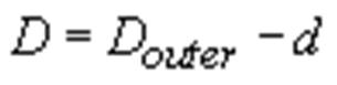
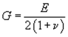
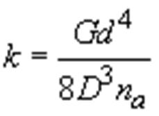
The spring constant k is function of the spring geometry and the spring material's shear modulus G, where G is found from the material's elastic modulus E and Poisson ratio n, and D is the mean diameter of the spring (measured from the centres of the wire cross sections),
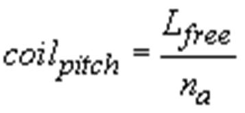
The distance between adjacent spring coils (defined as the coil pitch) is found by dividing the spring free length by the number of active coils,
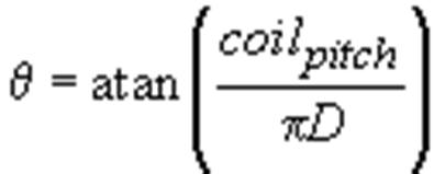
The rise angle of the spring coils (the angle between the coils and the base of the spring) is found from the arctangent of the coil pitch divided by the spring circumference,
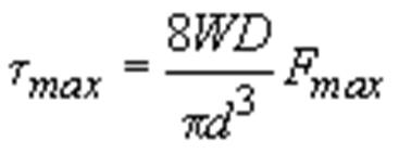
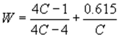
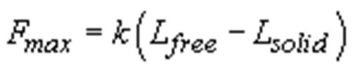
The maximum force the spring can take occurs when the spring is deformed all the way to its solid height, The maximum shear stress in the spring associated with the maximum force is given by, where W is the Wahl correction factor (accounting for spring curvature stress) and C is the spring index (essentially an aspect ratio of the spring cross section),
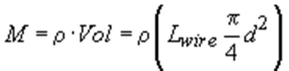
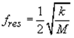
Finally, the lowest resonant frequency (in Hz) of the spring is found from the simple equation, where k is the spring constant from above and M is the spring mass (see derivation). The spring mass M can be found by weighing the spring, or by finding the spring volume and multiplying by its material density,
ISSN: 2321 9653; IC Value: 45.98; SJ Impact Factor: 7.538 Volume 10 Issue X Oct 2022 Available at www.ijraset.com
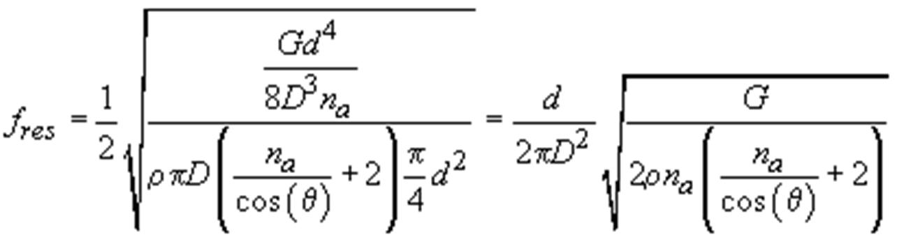
We can express the spring's lowest resonance in terms of basic spring geometry if we substitute for k and M in the equation for fres (and then eliminate Lwire). Doing so gives,
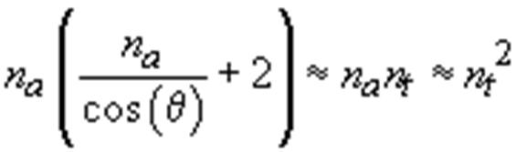
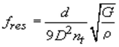
For springs with small rise angles and several active coils we can make the approximation, If we also allow the approximation, we can then simplify the resonant frequency formula to a form that can be found in several reference books,
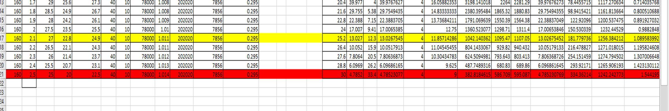
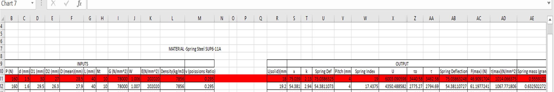
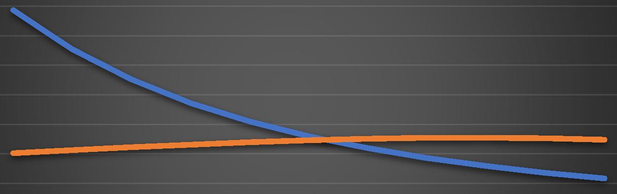
Based on these formulas we have created a excel sheet for determination of more accurate dimensions for our spring. We entered different inputs through which we can decide these parameters. We also use these Excel sheet for the selection of the material for the spring. In which we concluded that the Spring Steel SUP6 11A can be the suitable material for our model.


ISSN: 2321 9653; IC Value: 45.98; SJ Impact Factor: 7.538 Volume 10 Issue X Oct 2022 Available at www.ijraset.com

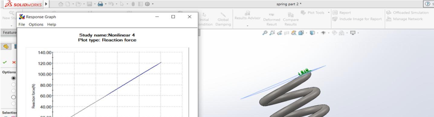
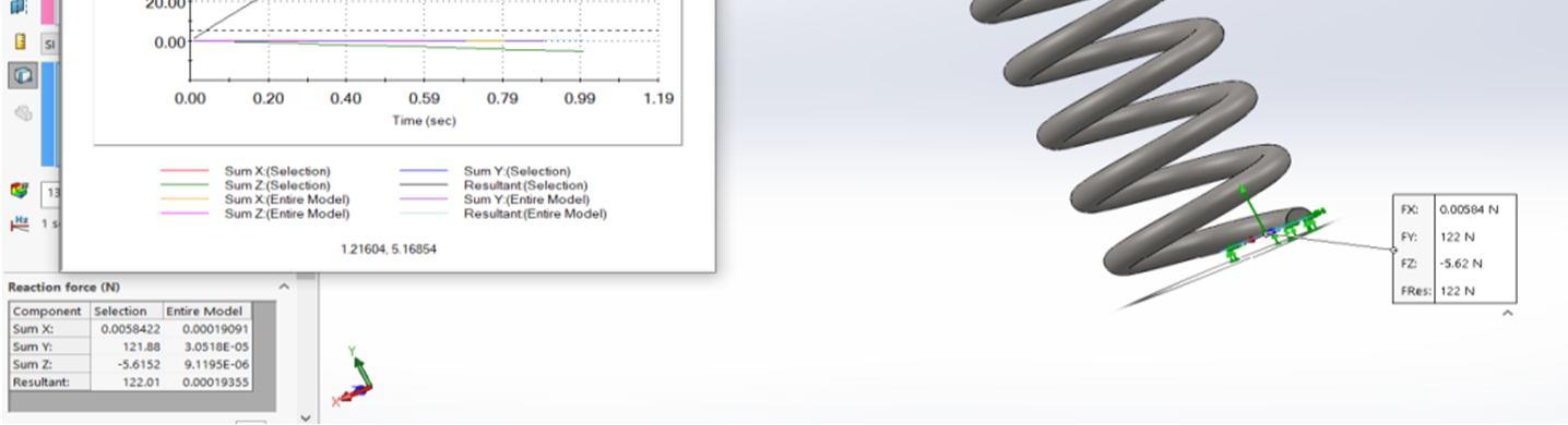
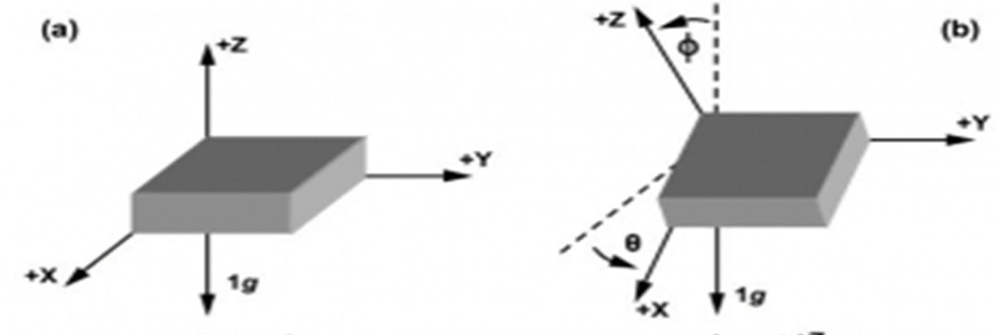
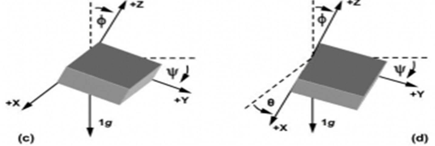
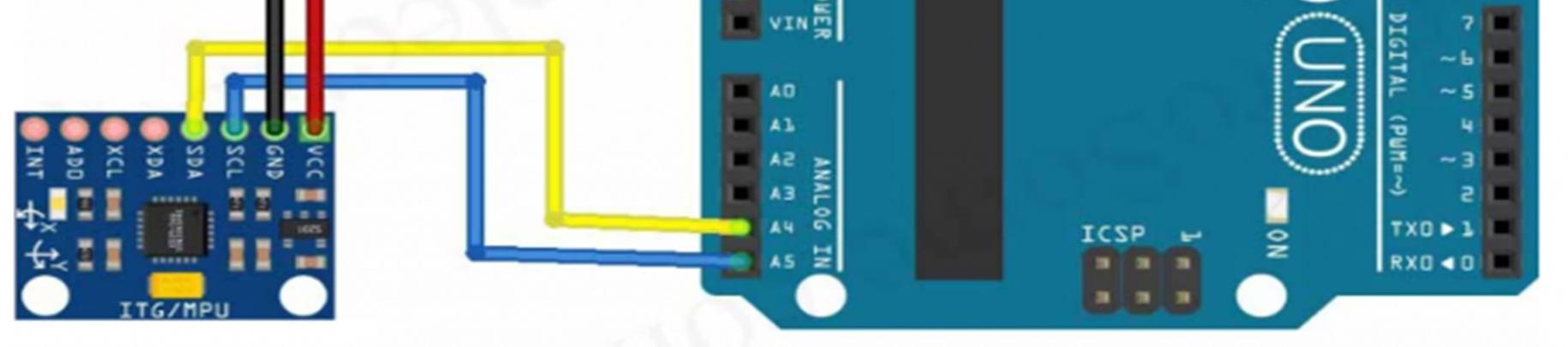
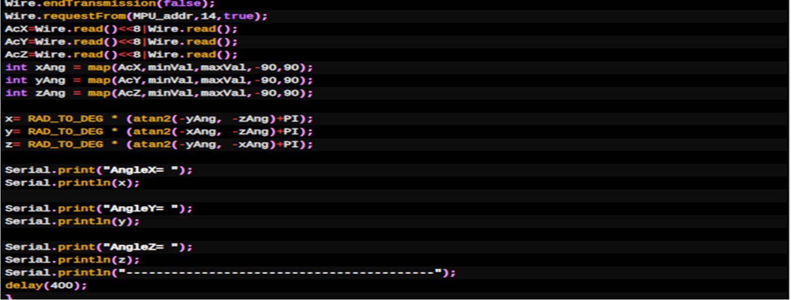
From this Simulation we can Conclude that our spring for this model or device is safe for the use in above conditions. The Accelerometer sends X, Y, and Z acceleration forces. We need to convert the forces into X, Y, Z 3D angle to determine the 3D Orientation of the sensor. The gyroscope measures rotational velocity or rate of change of the angular position over time, along the X, Y, and Z axis. It uses MEMS technology and the Coriolis Effect for measuring. The outputs of the gyroscope are in degrees per second, so in order to get the angular position, we just need to integrate the angular velocity. It is very accurate, as it contains a 16 bits analog to digital conversion hardware for each channel. Therefor it captures the x, y, and z channel at the same time. The sensor uses the I2C bus to interface with the Arduino. The MPU 6050 is not expensive, especially when we see that it combines both an accelerometer and a gyro.The picture here shows how the Accelerometer will calculate the angles along the 3 axis with the use of MEMS technology

ISSN: 2321 9653; IC Value: 45.98; SJ Impact Factor: 7.538 Volume 10 Issue X Oct 2022 Available at www.ijraset.com


ISSN: 2321 9653; IC Value: 45.98; SJ Impact Factor: 7.538 Volume 10 Issue X Oct 2022 Available at www.ijraset.com
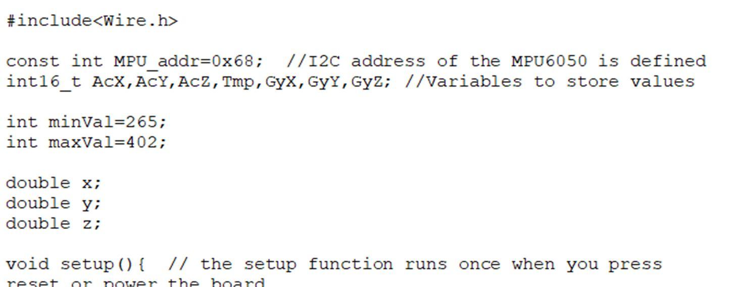
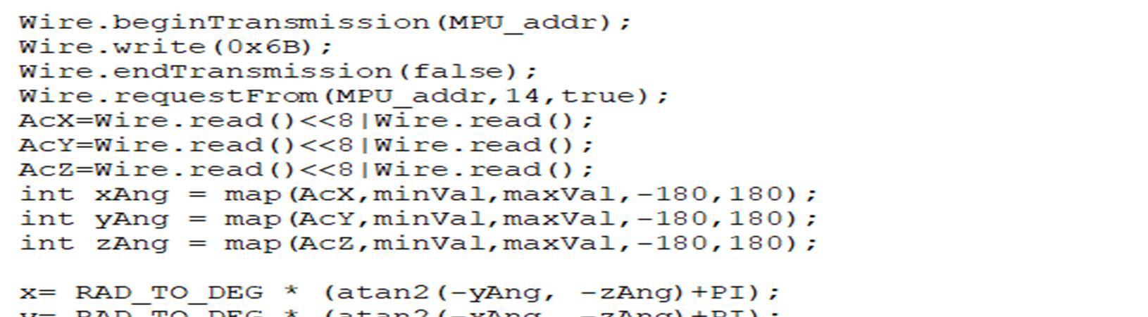
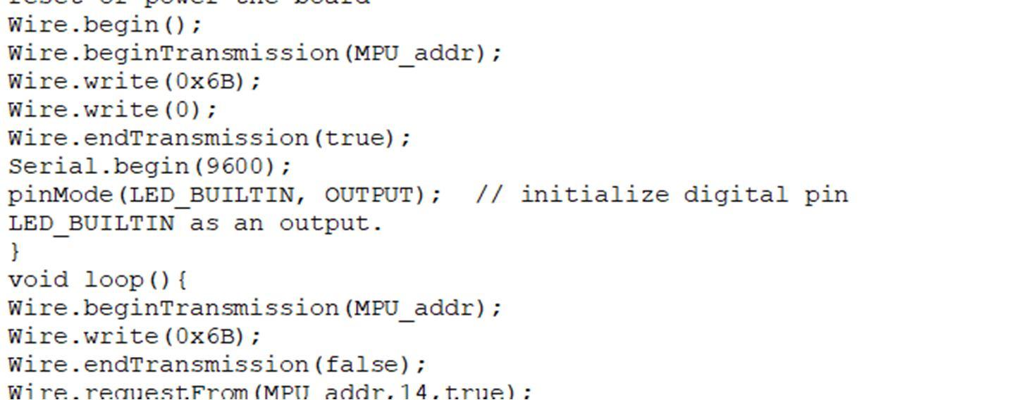
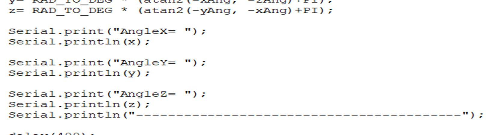
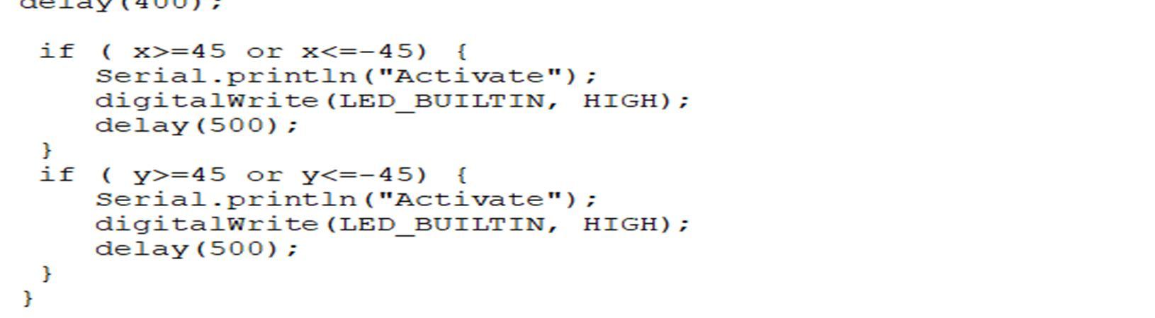
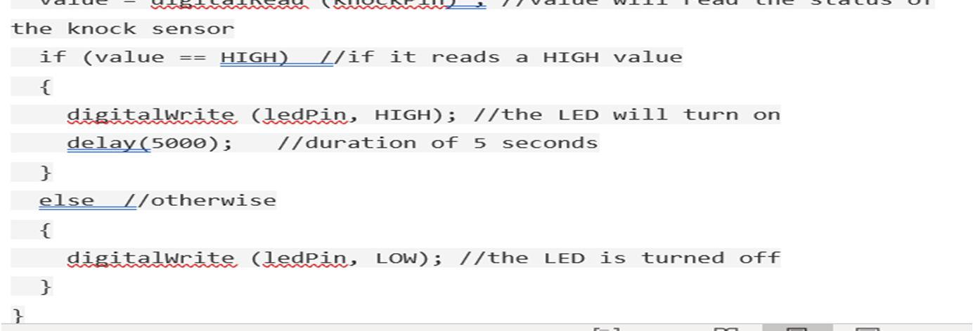
This is the sample code which we referred Here we have done some changes to the Sample Code. We have added condition to x and y which would activate the LED when the Roll or the Pitch Value of the sensor goes beyond + 45 deg. The LED will later be replaced by the Actuator
ISSN: 2321 9653; IC Value: 45.98; SJ Impact Factor: 7.538 Volume 10 Issue X Oct 2022 Available at www.ijraset.com
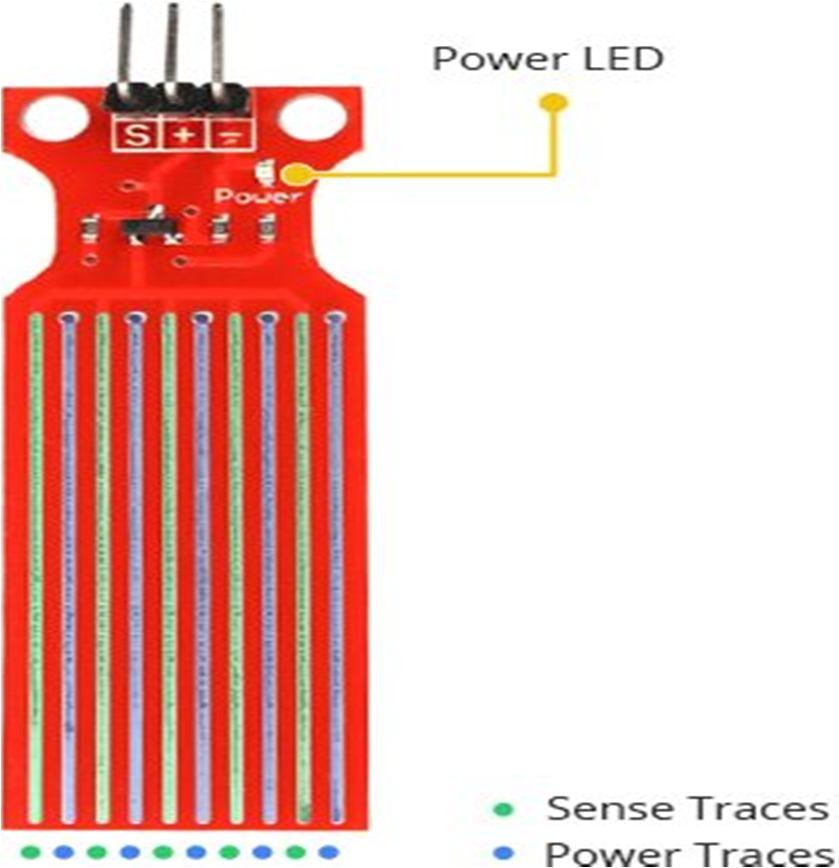
The sensor has a series of ten exposed copper traces, five of which are power traces and five are sense traces. These traces are interlaced so that there is one sense trace between every two power traces. Usually these traces are not connected but are bridged by water when submerged. There’s a Power LED on the board which will light up when the board is powered.
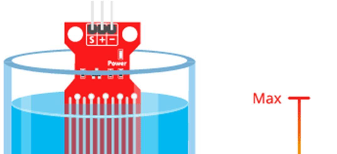
The working of the water level sensor is pretty straightforward. The series of exposed parallel conductors, together acts as a variable resistor (just like a potentiometer) whose resistance varies according to the water level. The change in resistance corresponds to the distance from the top of the sensor to the surface of the water.The resistance is inversely proportional to the height of the water:
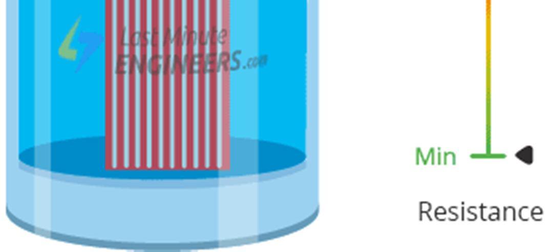
a) The more water the sensor is immersed in, results in better conductivity and will result in a lower resistance.
b) The less water the sensor is immersed in, results in poor conductivity and will result in a higher resistance.
The sensor produces an output voltage according to the resistance, which by measuring we can determine the water level.
ISSN: 2321 9653; IC Value: 45.98; SJ Impact Factor: 7.538 Volume 10 Issue X Oct 2022 Available at www.ijraset.com
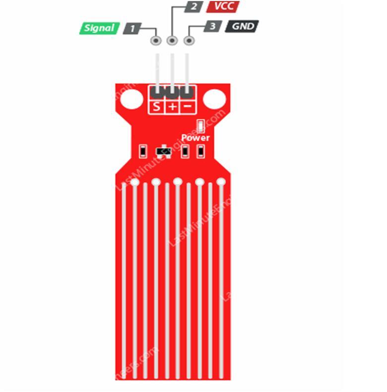
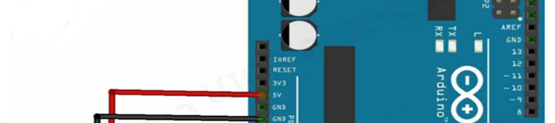
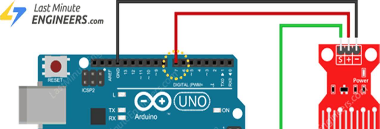
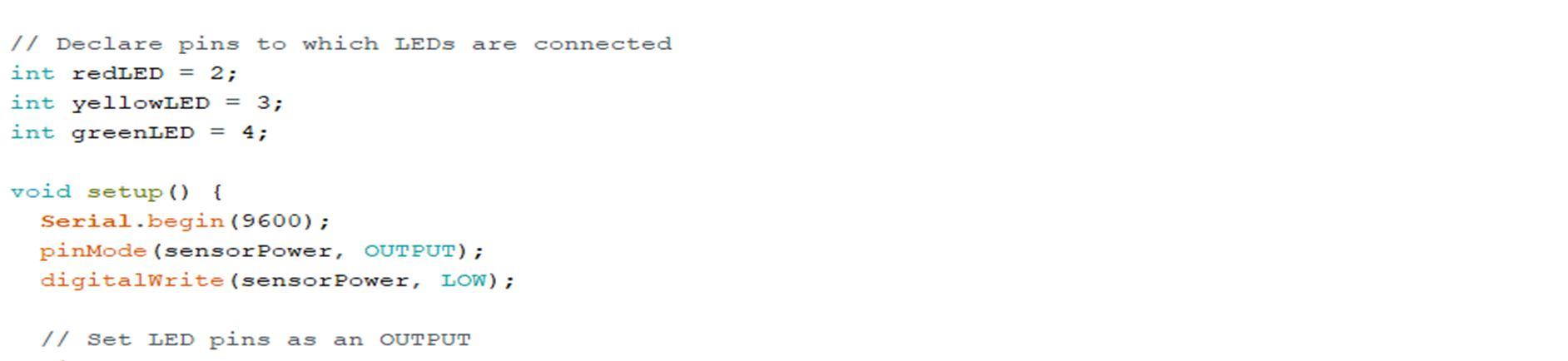
The water level sensor is super easy to use and only has 3 pins to connect.
S Signal pin is an analog output that will be connected to one of the analog inputs on your Arduino. +(VCC) pin supplies power for the sensor. It is recommended to power the sensor with between 3.3V 5V. Please note that the analog output will vary depending on what voltage is provided for the sensor. (GND) is a ground connection.
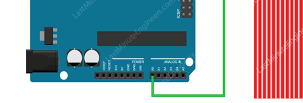
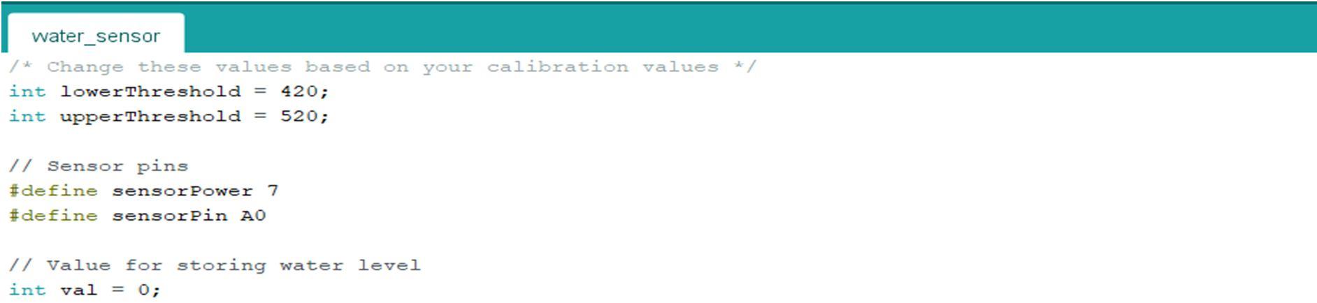
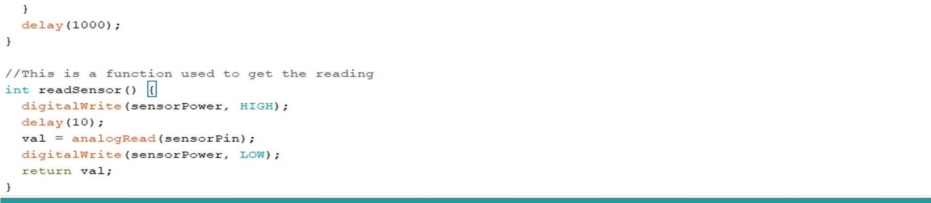
Let’s hook the water level sensor up to the Arduino. First you need to supply power to the sensor. For that you can connect the + (VCC) pin on the module to 5V on the Arduino and (GND) pin to ground. However, one commonly known issue with these sensors is their short lifespan when exposed to a moist environment. Having power applied to the probe constantly speeds the rate of corrosion significantly. To overcome this, we recommend that you do not power the sensor constantly, but power it only when you take the readings. An easy way to accomplish this is to connect the VCC pin to a digital pin of an Arduino and set it to HIGH or LOW as per your requirement. So, we’ll connect the VCC pin to the digital pin #7 of an Arduino. Finally, connect the S (Signal) pin to the A0 ADC pin on your Arduino. The following illustration shows the wiring.
ISSN: 2321 9653; IC Value: 45.98; SJ Impact Factor: 7.538 Volume 10 Issue X Oct 2022 Available at www.ijraset.com
ISSN: 2321 9653; IC Value: 45.98; SJ Impact Factor: 7.538
Volume 10 Issue X Oct 2022 Available at www.ijraset.com
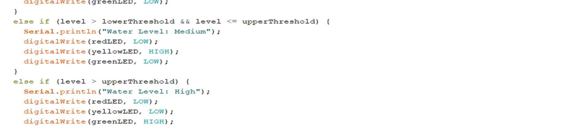
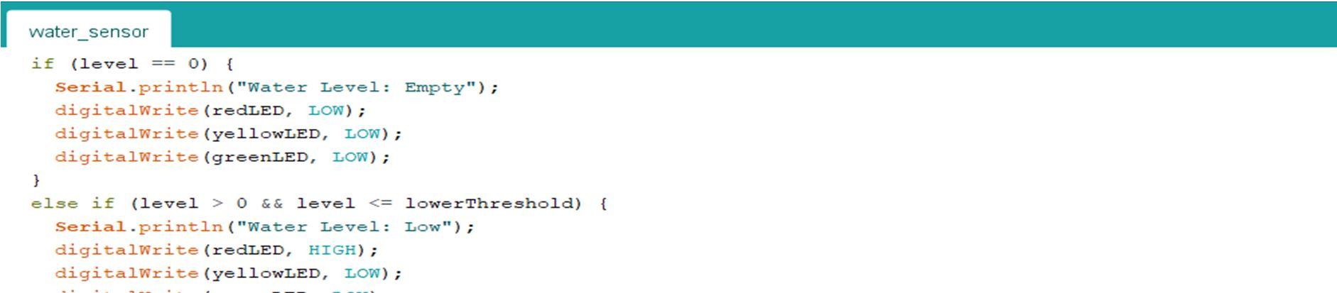
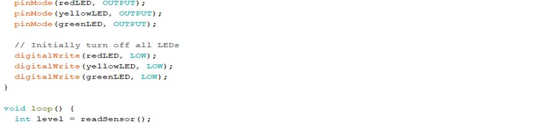
This sensor works according to level of water inside the car. we defined initial value for sensor in coding. Sometime car goes through some water present on road during the rainy season. Also, the during washing of car sensor get some input so avoid such disturbances we made the changes in coding according to requirement. We defined three level in high, medium, low according to this sensor work. if water level less than low range sensor doesn’t work. if water level is more than medium level sensor passed the information to the actuator and then mechanism works. There is delay of 10 milliseconds.
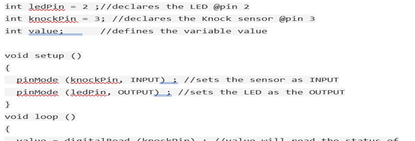
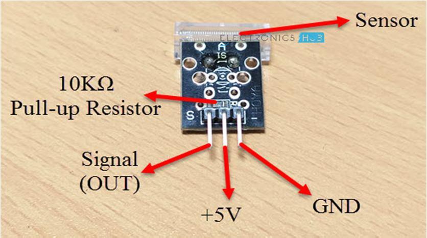
A Knock Sensor or a Vibration Sensor is a simple device that detects vibrations or shocks from knocking or tapping it. It is basically an electronic switch which normally opens. When it detects any shock or vibrations, it closes (for that moment and returns back to its default open position). The Knock Sensor is not a very sensitive device. It doesn’t detect small knocks or taps but rather requires hard vibrations for it to detect. Several Knock Sensors are available in the market and the cheaper ones are called KY 031 Knock Sensors. A typical knock sensor consists of the main sensing element, which is a conductive vibrating spring, a Resistor and three Pins. The three pins of the Knock Sensor Module are GND, +5V and S. The following image shows the components of a Knock Sensor Module as well as the pins on it.
If you take a look at the schematic of the knock sensor, it basically consists of a switch and a resistor. The Vibrating Spring is represented as a switch. The output pins of the sensor (which is connected to one end of the switch) is pulled HIGH with the help of a 10KΩ Pull up resistor. Under normal condition i.e. when there is no shock or vibrations, the output of the Knock Sensor is HIGH. When the sensor detects any vibrations or shocks, the vibrating spring i.e. switch closes and hence the output of the sensor (at the output pin) will become LOW.
ISSN: 2321 9653; IC Value: 45.98; SJ Impact Factor: 7.538
Volume 10 Issue X Oct 2022 Available at www.ijraset.com
Tinker cad is a free, online 3D modelling program that runs in a web browser, known for its simplicity and ease of use. Since it became available in 2011 it has become a popular platform for creating models for 3D printing as well as an entry level introduction to constructive solid geometry in schools.Tinker cad uses a simplified constructive solid geometry method of constructing models. A design is made up of primitive shapes that are either "solid" or "hole". Combining solids and holes together, new shapes can be created, which in turn can be assigned the property of solid or a hole. In addition to the standard library of primitive shapes, a user can create custom shape generators using a built in JavaScript editor. Tinker cad was convenient as it was a free, online platform but was discarded from this project due to its lack of support for the sensors used in our design.So the alternative found to run the sensor simulations was Proteus.
The Proteus Design Suite is a proprietary software tool suite used primarily for electronic design automation. The software is used mainly by electronic design engineers and technicians to create schematics and electronic prints for manufacturing printed circuit boards. The Proteus Design Suite is a Windows application for schematic capture, simulation, and PCB (Printed Circuit Board) layout design. It can be purchased in many configurations, depending on the size of designs being produced and the requirements for microcontroller simulation. All PCB Design products include an auto router and basic mixed mode SPICE simulation capabilities. Schematic capture in the Proteus Design Suite is used for both the simulation of designs and as the design phase of a PCB layout project. It is therefore a core component and is included with all product configurations.
The micro controller simulation in Proteus works by applying either a hex file or a debug file to the microcontroller part on the schematic. It is then co simulated along with any analog and digital electronics connected to it. This enables its use in a broad spectrum of project prototyping in areas such as motor control, temperature control and user interface design. It also finds use in the general hobbyist communityand, since no hardware is required, is convenient to use as a training or teaching tool. Support is available for co simulation of:
1) Microchip Technologies PIC10, PIC12, PIC16,PIC18,PIC24,dsPIC33 Microcontrollers.
2) Atmel AVR (and Arduino), 8051 and ARM Cortex M3 Microcontrollers
3) NXP 8051, ARM7, ARM Cortex M0 and ARM Cortex M3 Microcontrollers.
4) Texas Instruments MSP430, PICCOLO DSP and ARM Cortex M3 Microcontrollers.
5) Parallax Basic Stamp, Freescale HC11, 8086 Microcontrollers.
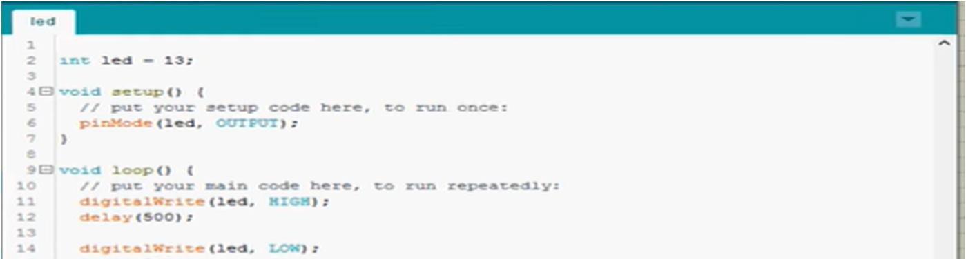
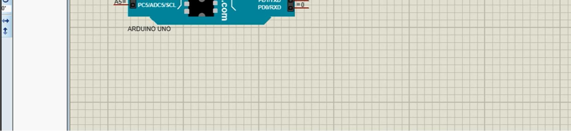
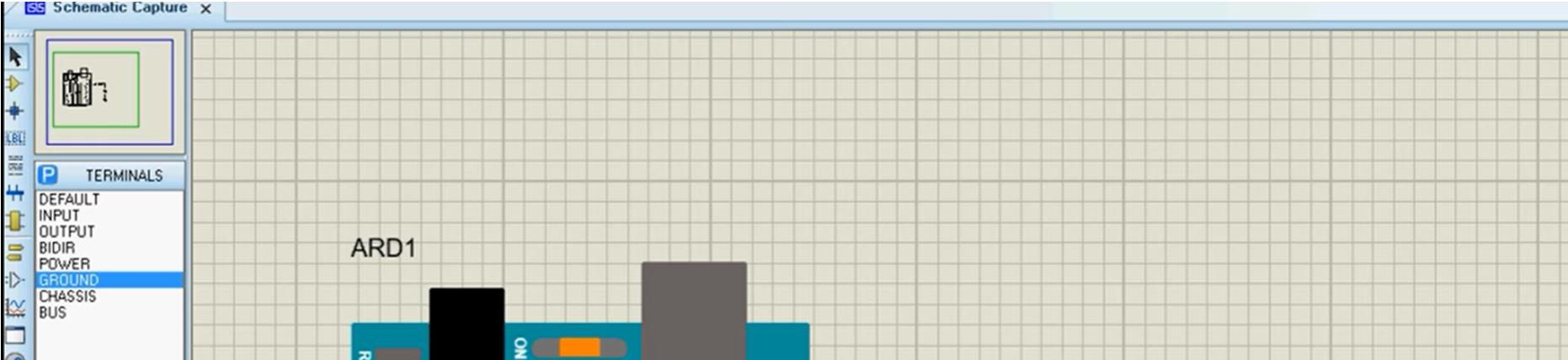
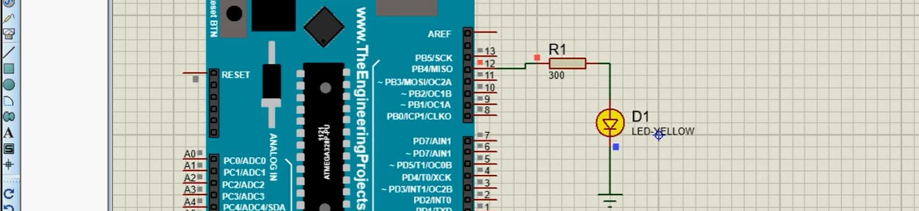
The 3D Viewer module allows the board under development to be viewed in 3D together with a semi transparent height plane that represents the boards enclosure. STEP output can then be used to transfer to mechanical CAD software such as Solidworks or Autodesk for accurate mounting and positioning of the board. Proteus successfully fits all the requirements of the project and will be soon used to run the simulations for the sensors. For the time being, a trial run was done for the software for a simple LED blinking code with Arduino, the details are shown in the images below.
ISSN: 2321 9653; IC Value: 45.98; SJ Impact Factor: 7.538
Volume 10 Issue X Oct 2022 Available at www.ijraset.com
Arrangement of Arduino in Proteus Software with it’s programming
We intend to ensure the further safety of the passenger in the drowning scenario by further increasing the time of the car drowning. Research says that it takes around 30 120 seconds for a car to drown. We intend to increase that time, thus giving the passenger more time to escape the car in a drowning scenario. We intend to do this by adding an airbag type mechanism below the car. This will be similar to the mechanism used in space shuttles as they land in the ocean. Furthermore, research will be done to make this a better part with the integration of our project.
[1] Strength Investigations on Laminated Windshield, A Varun1 , C G Nandakumar2
[2] Failure Analysis of Composite Windshield Sachin Patil M 1 , Dr.B.Ravindra2.
[3] A STUDY ON TOUGHENED GLASS USED FOR VEHICLES AND ITS TESTING METHODS.
[4] Strength Investigations on Laminated Windshield, A Varun1 , C G Nandakumar2
[5] Failure Analysis of Composite Windshield Sachin Patil M 1 , Dr.B.Ravindra2.
[6] A STUDY ON TOUGHENED GLASS USED FOR VEHICLES AND ITS TESTING METHODS .
[7] https://byjus.com/physics/working of electric bell/
[8] https://steemit.com/utopian io/@ted7/arduino 101 using a knock impact sensor ky 031
[9] https://www.amazon.in/Ztylus Stinger Emergency Escape Tool
[10] https://www.michiganradio.org/post/vehicle escape tools dont work laminated windows
[11] http://www.autoglass.com.sg/rear windscreen door glass
[12] https://www.google.com/search?q=automatic+centre+punch+gif
[13] https://how2electronics.com/measure tilt angle mpu6050 arduino/
[14] https://en.wikipedia.org/wiki/File:Operation_of_Sweet_patent_automatic_center_punch.gif
[15] https://www.azosensors.com/Article.aspx?ArticleID=40#:~:
[16] https://www.youtube.com/watch?v=03ASg7 NE04
[17] http://www.fused aluminumoxide.com/sale 10340985 al2o3 95 brown fused aluminium oxide aluminium oxide media.html
[18] https://lastminuteengineers.com/water level sensor arduino tutorial/