10 X October 2022 https://doi.org/10.22214/ijraset.2022.45510
ISSN: 2321 9653; IC Value: 45.98; SJ Impact Factor: 7.538 Volume 10 Issue X Oct 2022 Available at www.ijraset.com

ISSN: 2321 9653; IC Value: 45.98; SJ Impact Factor: 7.538 Volume 10 Issue X Oct 2022 Available at www.ijraset.com
Dr. Sachin Gee Paul1 , Ashik Santhosh2 , Binto Thambi3 , Denit Shibu4 , Devaprasad P5
1AssosiateProfessor, Electrical and Electronics, Ilahia College of Engineering and Technology, Mulavoor, Kerala, India 2, 3, 4, 5Electrical and Electronics, Ilahia College of Engineering and Technology, Mulavoor, Kerala, India

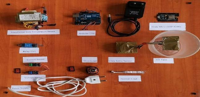
Abstract: Distribution Transformers are a critical part of the electrical power system. Data collection and transformer condition monitoring are very important for preventing transformer failures. In order to monitor the transformer, the operator has to visit the transformer premises. The main purpose of the project is to monitor the transformer parameters such as temperature, current, voltage, and oil level using IoT. Sensor networks are used to obtain transformer parameters. This system can minimize work effort, improve accuracy, reliability, and efficiency. This received data is sent to the Arduino UNO microcontroller. The recorded data is sent through ESP 8266 Wi Fi module and accessed from anywhere around the world using IOT technology using HTTP protocol. This helps in identifying without human dependency. This helps in identifying and solving a problem before a failure without human dependency.
Keywords: IoT (Internet of Things); ESP 8266; Arduino UNO; OverLoad; Over Voltage; Distribution Transformer.
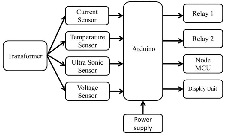
TheInternetofThingsreferstothecollectivenetworkofconnecteddevicesandthetechnologythatfacilitatescommunication between devicesandthecloud, aswellasbetween thedevicesthemselves. IOTallows objectstobesensedor controlledremotelyacrossexisting networkinfrastructure, creatingopportunitiesfor moredirectintegration ofthephysicalworldintocomputer basedsystemsandresulting in improvedefficiency, accuracy, andeconomicbenefitsotherthanreducedhumanintervention.Transformerdurabilitycanbeincreased by operating them in good and rated condition. Overloading and inefficient cooling of transformers can cause unexpected failure in transformers, which can disturb the delivery of electricity to many consumers. SCADA can be used for online monitoring of power transformers, but it is an expensive approach. Themanualcheckupofrisein voltage,riseintemperature,loadcurrent, oilleveletc. tendstobemorecomplex. Thismanualmonitoring doesnotprovideinformationaboutoccasionaloverloadsandoverheatingoftransformer oilandtemperature.Theproposedsystembased on IOTcolletskeyoperationalparametersofthetransformerwhich willhelptheutilitiestooptimallyusetheirtransformersandkeepthe asset in operation for longer period. Thus the system helps to improve transformer life by identifying the problem before the failure occur.Themonitoredparametersarecomparedtothetransformer'sratedvalues, andtheArduinoisprogrammedtotakeprotectiveaction if the monitored values surpass the rated values, also displays the monitored values on a remote PC.
Fig.1: Block Diagram of Proposed System
ISSN: 2321 9653; IC Value: 45.98; SJ Impact Factor: 7.538 Volume 10 Issue X Oct 2022 Available at www.ijraset.com
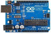
Arduino is open source hardware and software user community that designs and manufactures single boards. Microcontrollers and microcontrollerkitsforbuilding digitaldevicesandinteractiveobjectsthatcansenseand controlbothphysicallyanddigitally.[4]Withthe help of Arduino, we are able to read values from sensors and also convert them to output.
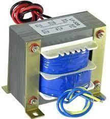
Thetransformerisastaticelectricaldevicethattransfersenergybyinductivecouplingbetween itswindingcircuits.Avaryingcurrentin the primarywinding creates a varying magnetic flux in the transformer's core and thus a varying magnetic flux through the secondary winding. This varying magnetic flux induces a varying electromotive force (E.M.F) or voltage in the secondary winding.
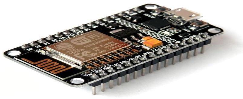
Node MCU is an open source Lua based firmware and development board specially targeted for IoT based Applications. It includes firmwarethatrunsontheESP8266Wi FiSoCfromEspressifSystems, andhardwarewhich isbasedontheESP 12module.NodeMCU has four pins available for SPI communication.
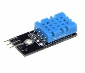
Temperaturesensorscalculatetheamountofheatenergyor even coldnessgeneratedbyanobjector device,allowingusto"feel"ordetect any physical change in that temperature, providing an analogue or digital output. The DHT11 series of precision integrated circuit temperature sensors have an output voltage that is proportional to the temperature in Celsius (Centigrade). In comparison to linear temperature sensors measured in degrees Kelvin, the DHT11 has the advantage of not requiring the consumer to remove a significant constant voltage from the output to obtain convenient Centigrade scaling


ISSN: 2321 9653; IC Value: 45.98; SJ Impact Factor: 7.538 Volume 10 Issue X Oct 2022 Available at www.ijraset.com
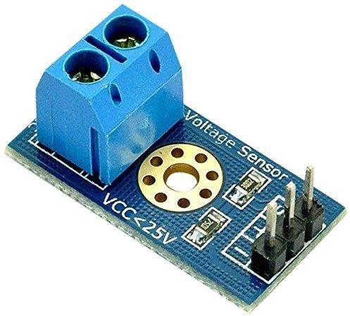
Inan electricalpower device,itisusedtocalculatevoltage. Whenavoltageistoohighforaninstrumenttouse,itcan bescaleddowntoa standardizedlowvalue.Avoltagesensormeasuresthevoltageinawireandproducesasignalproportionaltothatvoltage.Thegenerated signal could be analogue voltage, current, or even digital output. It can then be used to display the measured voltage on a voltmeter.
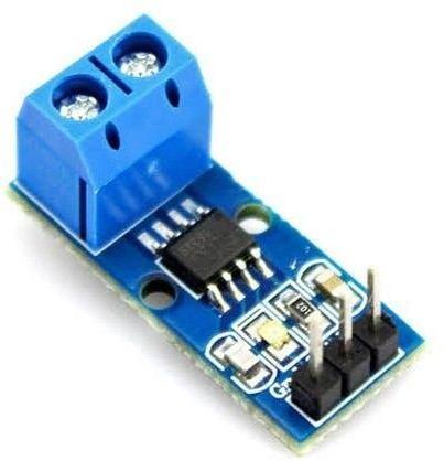
New sensors are a cost effective and accurate approach for current sensing in processing, industrial, and networking networks. Typical implementations include motor control, load monitoring and maintenance, over current fault detection, and any intelligent power management system. A current sensor senses and produces a signal proportional to the electric current flowing through a cable. The generatedsignalcouldbeanaloguevoltage, current,orevendigitaloutput.Thecurrentmeasuredinanammeter willthenbeshownusing it.
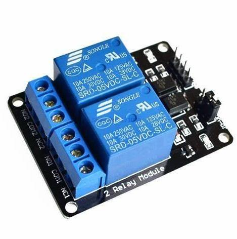
Everyelectricalsystem'smakeandbreakcontactishandledbytheSwitchingUnit. Thisunit,ontheotherhand, ismadeupofdriversand actuators.Therelayispoweredby[C1815]transistors,whichareusedasmotors. Relaysareusedasactivecomponents,andresistorsand diodes are used as passive elements. The processing unit's output switches on the appropriate transistor, which then activates the relays. The incoming phases from the public utility supply are connected to the relay terminals, and the load's single phase output is also connected to the relay outputs.
The display unit shows the status of the system's phase voltage switching and digital range as a result of the resulting phase voltage switching. It is used to view the chosen healthiest available step to feed the load as it is processed.
ISSN: 2321 9653; IC Value: 45.98; SJ Impact Factor: 7.538
Volume 10 Issue X Oct 2022 Available at www.ijraset.com
9) Connecting Wire Connecting wires allow current to travel from one point to another in a circuit. Because electricity needs a medium to move. 10) Ultrasonic Sensor
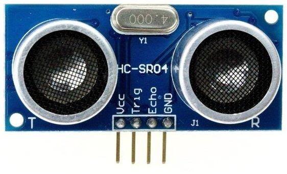
An ultrasonic sensor is an instrument that measures the distance to an object using ultrasonic sound waves. An ultrasonic sensor uses a transducer to send and receive ultrasonic pulses that relay back information about an object’s proximity. High frequency sound waves reflect from boundaries to produce distinct echo patterns.
Apower supplyisan electricaldevicethatsupplieselectricpower toan electricalload. Themainpurposeofapower supplyistoconvert electric current from a source to the correct voltage, current, and frequency to power the load.
In this existing system the worker has to find the fault manually
Drawbacks of existing system: The time requires for identifying the fault is more. The worker has to go manually to identify the fault.
Sensor based intelligent fault detection system is mainly conceptualized in such a way that the time required to identify the fault is reduced
Advantages of proposed system: The time required for identifying the fault is less. The microcontroller will send the identified fault to the WEB SERVER using IOT technology.
The software algorithms are developed in Arduino IDE software which is an open source application. This application allows you to encode, compileanduploadfilestoyour Arduinodevice. Allthesethingshappen withthehelpofmicrocontroller’snativelanguage.The algorithm starts with the initialization ofthe I/O port data stream. Then according tothe algorithmhe starts tocommand the sequence. Wehavetotakevoltage, current,temperatureandoillevelreadingscontinuouslyandsendthemtoBlynkAppbyusingWi Fi. With the help of the Blynk App the operators can monitor data anytime, anywhere. Also it’s an open source application. If anyparameter value exceeds beyond its threshold value then Arduino trips the power supply.
Theproposedsystemusesan Arduinotomonitoradistributiontransformer'svoltage,current,oillevel,andtemperature.Thesedistribution transformer parameterscan bedisplayed on acomputer or mobiledeviceusingIoTtechnology, which isahigh performancetechnology thatintegratesdatabaserecordingandsimulation onasingleplatform.Themonitoredparametersarecomparedtothetransformer'srated values,andtheArduinoisprogrammedtotakeprotectiveactionifthemonitoredvaluessurpasstheratedvalues,displayingthevalueona remote PC. Transformer temperature and oil level was detected using an LM35 temperature sensor and a ultrasonic sensor.
ISSN: 2321 9653; IC Value: 45.98; SJ Impact Factor: 7.538
Volume 10 Issue X Oct 2022 Available at www.ijraset.com
The Arduino receives these values as inputs and executes the desired operation. The Arduino will switch off the power supply to the deliverytransformerifthevoltageandcurrentvaluessurpasstheratedvalues(overloading). Ifthetemperatureofthedeliverytransformer increases above the rated values, the Arduino can switch off the power supply (overheating). The microcontroller is programmed to constantly scan the transformer and adjust the parameters at fixed intervals.
Comparedtomanualmonitoring,theIOT basedmonitoringofdistributiontransformerisquiteusefulfor us. Becauseitisnotpossibleto monitorthevoltage, current, oillevelandtemperaturerisemanually. Soitisalsoreliablefor us. Ifanyabnormality occurs, theoperator gets a notification in real time and automatic tripping of the circuit takes place to prevent any failures of distribution transformers. Thus, wecan recover thesystemin lesstimeandfaultsbeforeanyuncertain failures. Thus, thissystemiscost saving. Asthecontroller that we used has a small size compared to other controllers. The overall size of the whole setup is also small.
[1] SajidurRahman, Shimanta KumarDey,BikashKumarBhawmickandNipu KumarDa,“DesignandImplementationofReal TimeTransformerHealthMonitoring System Using GSM Technology” International Conference on Electrical, Computer and Communication Engineering (ECCE) 2017.
[2] Siddhant Gaikwad, Raj Mehta, Prathamesh Shetye, Jay Khut, Kavita Bani, “GSM based Distribution Transformer Monitoring System” International Journal of Engineering Research & Technology (IJERT) 2017.
[3] “Determination of the breakdown voltage at power frequency Test Method,” in International Standard (IEC 60156), Second. IEC, 1995.
[4] GSM BasedDistributionTransformer MonitoringSystem. Abdul Rahman AI Ali, Abdul Khaliq&MuhammadArshadSchool ofEngineering,AmericanUniversity of
[5] Sharjah Box 26666, AUS, Sharjah, United Arab Emirate, IEEE MELECON 2004, May 12 15, 2004, Dubrovnik, Croatia
[6] Distribution Transformer Monitoring for Smart Grid in India, 1st IEEE International Conference on Power Electronics, Intelligent Control and Energy Systems (ICPEICES 2016).