
11 I January 2023 https://doi.org/10.22214/ijraset.2023.48620
ISSN: 2321-9653; IC Value: 45.98; SJ Impact Factor: 7.538
Volume 11 Issue I Jan 2023- Available at www.ijraset.com

ISSN: 2321-9653; IC Value: 45.98; SJ Impact Factor: 7.538
Volume 11 Issue I Jan 2023- Available at www.ijraset.com
Mr. Rajkumar. S1 , Mr. Pradeep. M2 , Mr. Mano Bharath M P3
1Marine multi NDT Inspector, Mispah Pipeline Inspection Services LLC, Abu Dhabi, UAE 2Assistant Professor, Dept of Mechanical Engineering, Karpagam institute of Technology, Coimbatore-641105
3U.G Scholar, Dept of Mechanical Engineering, Karpagam institute of Technology, Coimbatore-641105

Abstract: The use of polymeric materials has grown widely in various sectors such as packaging, building, electronic, automotive, and aerospace industries. Particularly, Ultra-High Molecular Weight Polyethylene has wide engineering applications and is used in large quantities in automotive oil pans, gears, slides, cams, bearings, fluid reservoirs, and the sports industry. Friction Stir Welding (FSW) is a solid-state process in joining thermoplastic materials. In this investigation, FSW process must be applied to join a UHMWPE plate of 8 mm thickness with specially designed hexagonal tool pin profile. The aim of this study is to examine the effect of main friction stir welding (FSW) parameters on the quality of UHMWPE plate welds. FSW machine, using a tool with a stationary shoulder and no external heating system. The welding parameters studied were the tool rotational speed which varied between 1300 and 1500 (rpm); the traverse speed which varied between 15 and 25 (mm/min), and the axial force ranging from 8 to 10 (KN). Good quality welds are achieved without using external heating, when the tool rotational speed and axial force are above a certain threshold. For high rotational speed and axial force welds have poor material mixing at the retreating side and mild voids at the nugget, tensile strength also obtained very poor. The hardness angle distortion and bead geometry also evaluated. Taguchi design optimum parameters and ANNOVA were found.

Keywords: FSW, Tool Profile, Taguchi, HRM, Polyethylene
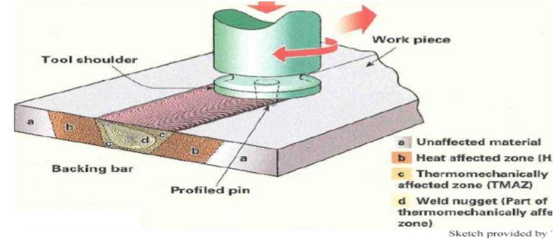
Friction stir welding (FSW) is an innovative solid-state joining process invented in the 1990s by The Welding Institute in the United Kingdom (UK). It is considered as one of the most significant welding process inventions in the last two decades. Compared to other solid-state joining processes such as rotary friction welding and inertial welding, the FSW process is unique in that it enables the advantages of solid-state joining for fabrication of continuous linear welds, the most common form of weld joint configurations that are predominately made by the arc welding processes in today’s i. The basic principles of FSW process are illustrated in Figure 2. The specially designed tool has two essential parts. The first part is the profiled pin extending along the rotating axis. The second part is the shoulder. Rotating at high angular speeds, the pin plunges into the work piece until the shoulder makes full contact with work piece surfaces. The rotating tool then moves along the joint line with the shoulder fully in contact with the work piece surface under a relatively high axial forging force. Owning to largely the frictional heating between the rotating tool and the work piece, the temperature in a column of work piece material under the tool is increased substantially, but remains below the melting point of the material. The increase in temperature softens the material, and allows the rotating tool to mechanically stir the softened material flowing to the backside of the pin where it is consolidated to form a metallurgical bond.
ISSN: 2321-9653; IC Value: 45.98; SJ Impact Factor: 7.538 Volume 11 Issue I Jan 2023- Available at www.ijraset.com
For this research, the objectives that are tried to achieve by the researcher are: To get optimum parameters for the materials under considerations i.e., UHMWPE 2. To investigate the Various Mechanical behaviors 3. Defects occurring during the welding process
The focus of the research work will be concentrated in the mechanical performance and the stir zone microstructure by FSW butt welded part having 100mm × 100mm × 8mm thick sheet UHMWPE using constant pin diameters. All the testing of welded part will be tested by ASTM standard. Hexagonal pin tool will used to conduct experiments. In this research, Universal Testing Machine (UTM), Hardness testing machine IMAGE-J (Bead Geometry Analysis) will also be used to measure the. Friction stir processing is a method of changing the properties of a metal through intense, localized plastic deformation.
Friction stir welding (FSW) produces welds by using a rotating, non-consumable welding tool to locally soften a work piece, through heat produced by friction and plastic work, thereby allowing the tool to “stir” the joint surfaces. The dependence on friction and plastic work for the heat source precludes significant melting in the work piece, avoiding many of the difficulties arising from a change in state, such as changes in gas solubility and volumetric changes, which often plague fusion welding processes.
In recent years, the fuel consumption in automobile and other industries have been reduced considerably owing to awareness on environmental pollution. The automobile industry has inclined its focus towards the reduction of vehicle weight leading to control of energy consumption and CO2 emission. In order to reduce the vehicle weight, automobile industries are looking for thermoplastics instead of conventional engineering materials. The choice of thermoplastic materials is its high stiffness-to-weight ratio and easy production of complex design. The reinforced fiber thermosets consumes long production cycle times due to curing of the materials. Thermoplastics deform when subjected to heat beyond the melting temperature. The material typically regains original stiffness when the temperature is subsequently reduced below melting point. This characteristic of thermoplastics makes the manufacturing of the polymer component easy. A recent literature survey on the automotive and composite industry exposed vitality in development of thermoplastics. This development has facilitated the implementation of new manufacturing process and technologies in the automotive industry.
The recent developments in the thermoplastic technology are listed as follows:
1) Reduction in material cost
2) Industrialization and integration of composite manufacturing processes
3) Improvement in recyclability of composites and waste management
4) The enhancement of repair methods and damage detection
5) Development of hybridization and joining technology.
1) The main objective of this work is to study the mechanical properties of friction stir welded aluminum alloy plates with various tool profile analyzed. The study includes the mechanical property will be -weld condition. For this, a series of experiments were conducted based on constant parameter with various tool profiles.
2) Using the recommended parameter orthogonal array the first set of experiments was conducted on the UHMWPE plates. The UHMWPE plates were cut into required dimension of 100x100x8 mm for friction stir welding.
3) The plates were held firmly on a fixture which was fabricated essentially for the friction stir welding operation comprising of a load cell and a backing plate at the base. The first set of experiments was carried out with the chosen parameters; rotational speed, welding speed and axial load at 3 levels (low, mid, high). The first set of experiments were done without the addition of Sic particles to record the parent metal behavior in two different conditions namely, as-weld condition and annealed condition.
4) Taking the results of this study as a reference, second set of experiments of friction stir welding of UHMWPE plates with was conducted.
ISSN: 2321-9653; IC Value: 45.98; SJ Impact Factor: 7.538 Volume 11 Issue I Jan 2023- Available at www.ijraset.com
1) Machine Compatibility: Friction stir welding operation is done using the Czechoslovakian vertical milling machine shown in Figure 4.1. The quality of the welded joint is ascertained by visual inspection of weld bead and defect free joints along the weld region.
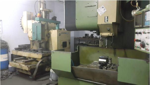
UHMWPE was used as base metal to perform friction stir welding in this study. The prepared samples to be welded using hexagonal profile tools with 6mm with shoulder diameters 18mm.
Basically, experimental design methods were developed original fisher. However experimental design methods are too complex and not easy to use. Furthermore, many experiments must be carried out when the number of the process parameters increases, to solve this problem, the Taguchi method uses a special design of orthogonal arrays to study the entire parameter space with a small number of experiments only. The experimental results are then transformed into a signal– to – noise (S/N) ratio to measure the quality characteristics deviating from the desired values Usually, there are three categories of quality characteristics in the analysis of the S/N ratio, i.e., the–lower–better, the–higher–better, and the–nominal–better The S/N ratio for each level of process parameter is compared based on the S/N analysis. Regardless of the category of the quality characteristic, a greater S/N ratio corresponds to better quality characteristics. Therefore, the optimal level of the process parameters is the level with the greatest S/N ratio Furthermore, a statistically significant with the S/N and ANOVA analyses, the optimal combination of the process parameters can be predicted. Finally, a confirmation experiment is conducted toverify
The signal-to-noise (S/N) ratio is calculated for each factor level combination. The formula for the smaller-is-better S/N ratio using base 10 log is:
S/N = -10*log (S (Y2)/n)
Where Y = responses for the given factor level combination and n = number of responses in the factor level combination.
The signal-to-noise (S/N) ratio is calculated for each factor level combination. The formula for the larger-is-better S/N ratio using base 10 logs is: S/N = -10*log (S (1/Y2)/n)
Where Y = responses for the given factor level combination and n = number of responses in the factor level combination.
The signal-to-noise (S/N) ratio is calculated for each factor level combination. The formula for the nominal-is-best I S/N ratio using base 10 log is:
S/N = -10*log (s2)
Where s = standard deviation of the responses for all noise factors for the given factor level combination.
ISSN: 2321-9653; IC Value: 45.98; SJ Impact Factor: 7.538 Volume 11 Issue I Jan 2023- Available at www.ijraset.com
Table 1. Levels and ranges of FSW process parameters Taguchi method L4 Factor
S.NO SPEED RPM TOOL-TR Mm/min AXFC KN 1 1300 15 8 2 1500 25 10
B. An Orthogonal Array L4 Formation
Table 2 L4 Array formation
SL.NO SPEED RPM TOOL-TR mm/min AXFC KN 1 1300 15 8 2 1300 25 10 3 1500 15 10 4 1500 25 8
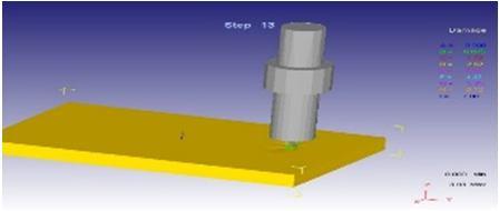
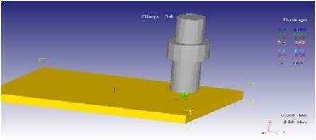
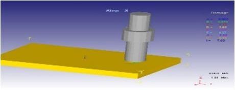
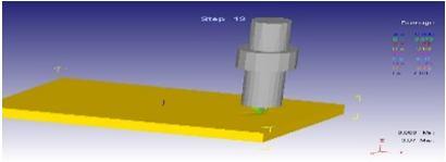
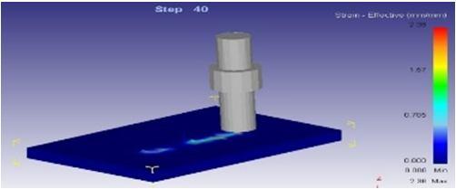
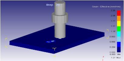
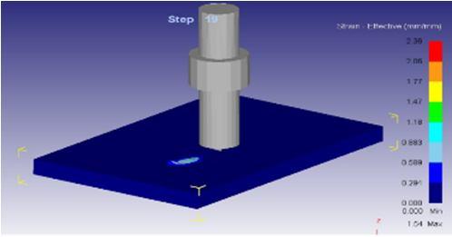
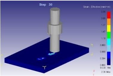
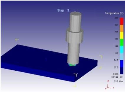
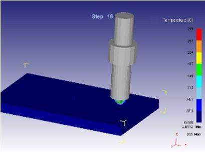
Finite element method (FEM) was applied in machining more than thirty years ago. The DEFORM® system is engineering software that enables designers to analyze metal forming, heat treatment, machining, and mechanical joining processes on the computer rather than the shop floor using trial and error. Process simulation using DEFORM has been instrumental in cost, quality, and delivery improvements at leading companies for two decades. Today’s competitive pressures require companies to take advantage of every tool at their disposal. DEFORM has proven itself to be extremely effective in a wide range of research and industrial applications. FEM has made tremendous achievements from simple two-dimensional orthogonal cutting simulation analysis in the beginning to three-dimensional orthogonal cutting and oblique cutting simulation at now, and from simple parameters setting to multiple parameters setting, etc. Actual cutting process occurs in three-dimensional deformation area. For example, tool and work piece have geometrical shapes with three-dimensional, relative movement between tool and work piece is not always orthogonal, some work piece materials are anisotropic and so on. With the improvement of the computing capacity of hardware, the threedimensional cutting simulation is primary direction to further study cutting mechanism. In recent years, some software’s are developed for simulation of cutting process such as ANSYS, DEFORM, ABAQUS, etc. DEFORM-3D is finite element simulation software based on process simulation system that synthesizes functions for modeling, shaping, and heat conducting, and forming equipment and so on. DEFORM-3D has some features such as good robustness, easy to use, powerful simulation engine, etc. In this experimental DEFORM-3D is used to research simulation of friction stir welding for UHMWE. Through 3D–Deformation analysis finally satisfied result obtained during maximum speed (1500RPM), minimum Tool Traverse (15mm/min) and maximum Axial Force (10KN).


ISSN: 2321-9653; IC Value: 45.98; SJ Impact Factor: 7.538 Volume 11 Issue I Jan 2023- Available at www.ijraset.com
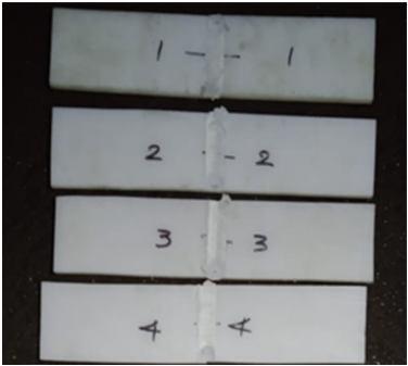
Fig: 6 After FSW of UHMWPE Plates
Rockwell Hardness systems use a direct readout machine determining the hardness number based upon the depth of penetration of either a diamond point or a steel ball. Deep penetration indicated a material having a low Rockwell Hardness number.
1) Hardness Value-HRM Value
Table: 5 hardness) –HRM value
SL.NO SPEED RPM TOOL-TR Mm/min AXFC KN HARDNESS VALUE
T1 1300 15 8 72 T2 1300 25 10 66 T3 1500 15 10 68 T4 1500 25 8 67
T2 test plate only found lower hardness compare than others.
Table: 6. Tensile strength value
SL.N O SPEED RPM TOOL-TR mm/min
AXIAL FORCE KN
TL KN TS N/mm2
T1 1300 15 8 2.91 11.73
T2 1300 25 10 2.84 10.33 T3 1500 15 10 3.46 12.85 T4 1500 25 8 2.03 7.82
SL. NO SPEED RPM
Table: 7. S-N Ratio table for Tensile strength
TOOLTR mm/min
AXIAL FORCE KN
TL KN TS N/mm2 SNRATIO
T1 1300 15 8 2.91 11.73 21.3860
T2 1300 25 10 2.84 10.33 20.2820
T3 1500 15 10 3.46 12.85 22.1781
T4 1500 25 8 2.03 7.82 17.8641
Technology (IJRASET
ISSN: 2321-9653; IC Value: 45.98; SJ Impact Factor: 7.538 Volume 11 Issue I Jan 2023- Available at www.ijraset.com
Table: 7.1 Response Table for Signal to Noise Ratios- Larger is better LEVEL SPEED RPM TOOL-TR Mm/min AXFC KN
1 20.83 21.78 19.63 2 20.02 19.07 21.23 Delta 0.81 2.71 1.60 Rank 3 1 2
Table: 7.2 Analysis of Variance Tensile strength
SOURCE DF SEQ SS ADJ MS F P
% OF CONTRIBUTION
SPEED 1 0.4830 0.4830 - - 3
TOOL TRAVERSE 1 10.3362 10.3362 - - 73 AX FC 1 3.2942 3.2942 - - 24 Error 0 - - 0 Total 3 14.1135 100
UHMWPE tensile specimen test executed FIE-600KN machine. During this tensile evaluation 3rd sample show has more tensile strength 12.85 N/mm2 .
Inadequate weld bead dimensions such as shallow depth of penetration may contribute to failure of a welded structure since penetration determines the stress carrying capacity of a welded joint. To avoid such occurrences the input or welding process variables which influence the weld bead penetration must therefore be properly selected and optimized to obtain an acceptable weld bead penetration and hence a high-quality joint. To predict the effect of welding process variables on weld bead geometry and hence quality researchers have employed different techniques.
A. Various Sizes of Bead Width and Depth of Penetration -UHMWPE FSW
Table: 8 Depth of Penetration
SL.NO AREA MEAN MIN MAX ANGLE LENGTH
1 0.513 196.834 156.667 232 0 16.789 0.028 209.9 199.667 227.333 90 0.917 2 0.66 230.575 186 251.333 0 18.022 0.06 226.052 194.333 248.667 90 1.648 3 0.798 226.975 182.333 250.333 0 19.383 0.097 228.427 197.667 244 90 2.346 4 0.779 219.121 145.333 250.667 0 14.262 0.125 206.746 196.333 217 90 2.295
SJ Impact Factor 7.538
ISRA Journal Impact Factor 7.894 |
ISSN: 2321-9653; IC Value: 45.98; SJ Impact Factor: 7.538
Volume 11 Issue I Jan 2023- Available at www.ijraset.com
After friction stir welding process the weld beads were observed. And following conclusion were informed below mentioned table.
Table: 9 Weld appearances
SL.NO SPEED RPM TOOL-TR Mm/min AXFC KN RESULT
T1 1300 15 8
T2 1300 20 9
T3 1300 25 10
T4 1400 15 9
Very fine texture but mild flash formed at the retreated Side
Very fine texture but mild flash formed at the retreated Side
Medium surface texture at weld region, but mild flash effect found Advanced Side
Very fine texture but it has no surface defects.
1) Through IMAGE-J software depth of penetration and bead width evaluation found during this investigation nominal bead width and depth obtained sample no 4.
2) No of 4th specimen is found smooth bead appearance it has no crack, porosity.
In this investigation, an attempt was made to select proper process parameter for with hexagonal tool pin profile to friction stir weld UHMWPE material.
3D–Deformation analysis satisfied result obtained during maximum speed (1500RPM), minimum Tool Traverse (15mm/min) and maximum Axial Force (10KN). From this investigation, the following important conclusions are derived The UHMWPE material could be welded by the hexagonal pin profile in the friction stir welding process. UHMWPE tensile specimen test executed FIE-600KN machine. During this tensile evaluation 3rd sample show has more tensile strength 12.85 N/mm2 . Hardness value found through hardness “M” - Scale tester (Model: sivaganga) major load applied 160kgf and ¼” ball indenter was used. Normal UHMWPE hardness was 90 HRM. After welded hardness test were evaluated near bead profile of advancing and retreating side. Welded area structure has changed from hard to softly.
Through IMAGE-J software depth of penetration and bead width evaluation found during this investigation nominal bead width and depth obtained sample no 4. No of 4th specimen is found smooth bead appearance it has no crack, porosity. Angle distortion analyzed through AUTOCAD software. During the inspection plate no 4 found no deviation from the axis. Based on the Taguchi design optimized parameter was UHMWPE for 8mm with executed hexagonal profile A3, B1, & C2 – (Speed 1500 RPM, TR 15 mm/min & AF 10KN) and tensile strength majorly influenced with tool Traverse 73%.
[1] N. Mendes Effect of friction stir welding parameters on morphology and strength of acrylonitrile butadiene styrene plate welds Materials and Design 58 (2014) 457–464
[2] ARMAG˘ ARICI Effects of double passes of the tool on friction stir welding of polyethylene JOURNAL OF MATERIALS SCIENCE 40 (2005) 3313 – 3316
[3] M. K. Bilici Effect of tool geometry on friction stir spot welding of polypropylene sheets Express Polymer Letters Vol.6, No.10 (2012) 805–813
[4] Yahya Bozkurt the optimization of friction stirs welding process parameters to achieve maximum tensile strength in polyethylene sheets Materials and Design 35 (2012) 440–445
[5] Imad M. Husain, Mechanical properties of friction-stir-welded polyamide sheets International Journal of Mechanical and Materials Engineering (2015) 10:18 DOI 10.1186/s40712-015-0047-6
[6] Arvin Bagheri, an experimental study on mechanical properties of friction stirs welded ABS sheets Materials and Design 43 (2013) 402–409
[7] K. Panneerselvam Effects and Defects of the Polypropylene Plate for Different Parameters in Friction Stir Welding Process International Journal of Engineering Research & Technology (IJERT) ISSN: 2319 - 1163
[8] K. Lenin Joining of Nylon 6 plate by friction stir welding process using triangular pin profile materials and Design 53 (2014) 302–307
[9] K. Panneerselvam Investigation on Effect of Tool Forces and Joint Defects during FSW of Polypropylene Plate Procedia Engineering 38 (2012) 3927-3940