
ISSN: 2321-9653; IC Value: 45.98; SJ Impact Factor: 7.538 Volume 10 Issue XII Dec 2022- Available at www.ijraset.com


ISSN: 2321-9653; IC Value: 45.98; SJ Impact Factor: 7.538 Volume 10 Issue XII Dec 2022- Available at www.ijraset.com
 Ahmed Eltayeb Ahmed Elbushra
1
MSc student1
, professor2 ,

2
, Prof. Dr. Alaa EL-ROUBY Department Electrical and Electronics Engineering, Ankara Yildirim Beyazit University.Abstract: Recently, a considerable amount of research has been conducted on multiple GNSS receivers using the Direct RF sampling concept. This approach greatly reduces the hardware requirements of the traditional receiver by placing the analog-todigital converter as close as possible to the antenna, eliminating the mixer stages. Furthermore, directly sampling the RF signal using the ADC allows for a more efficient design. In this paper, a Multi-GNSS Direct Radio Frequency Sampling Method is designed, optimized, and its performance is presented for several GNSS signals, including GPS L1, GPS L2, and GPS L5. The implemented method is used to find the ranges of valid sampling frequencies in single and multiple band RF signal cases. The algorithm presented results in an easier way to find valid sampling frequencies and a straightforward implementation without the need for complicated mathematical calculations. We consider aliasing issues and computational problems, providing a full theoretical and practical analysis compared to previously presented algorithms in the literature. This paper also examines the relationship between the sampling frequency, noise folding, and its effect on the signal-to-noise ratio (SNR), thus allowing for the selection of the optimal sampling frequency.
Keywords: GNSS, GPS, SNR, ADC, and direct radio frequency.
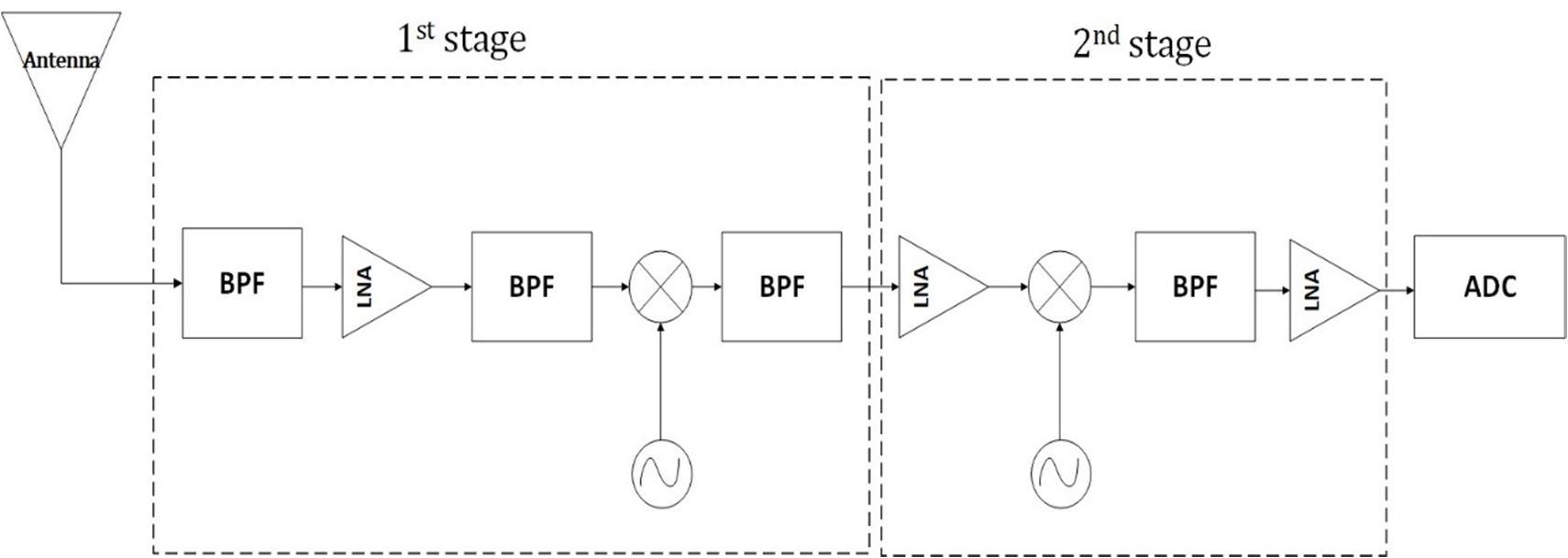
Over the last decades, the use of Global Navigation Satellite Systems (GNSS) is considered an important part of our life Started by the initial launch of the Global Positioning System (GPS) by the United States of America (USA) in 1978, followed by the increasing popularity of this navigation system, several governments started to develop and launch their own Global Navigation Satellite Systems (GNSS). Russia’s system (GOLNASS), the European Union (Galileo), the Chinese (Bei Dou) , and two regional systems – Japanese (QZSS) and Indian (IRNSS or NavIC) are the main GNSS operating nowadays [1]. The navigation signals are transmitted by those systems with different specifications in terms of frequency, bandwidth, and modulation. As a result, designing a multi-GNSS receiver has become a major research topic and many studies have been conducted looking for a more robust, affordable, higher precision, and greater integrity multi-GNSS receiver design. GNSS receivers consist of two main sections: hardware (RF front end) and software (DSP). The Hardware section has different possible RF architectures. For example, the superheterodyne, Heterodyne and Homodyne architecture are shown in Fig. 1, are frequently used[2], hence, referred to as the traditional RF front end. Other architectures such as software defined radio (SDR) had also been used. Those RF hardware architectures are capable of handling single frequency band and in case of needing to handle multiple frequency bands (to enhance reliability or accuracy for example) they need to be duplicated for each band and that increases cost, power consumption, and complexity of the RF front-end
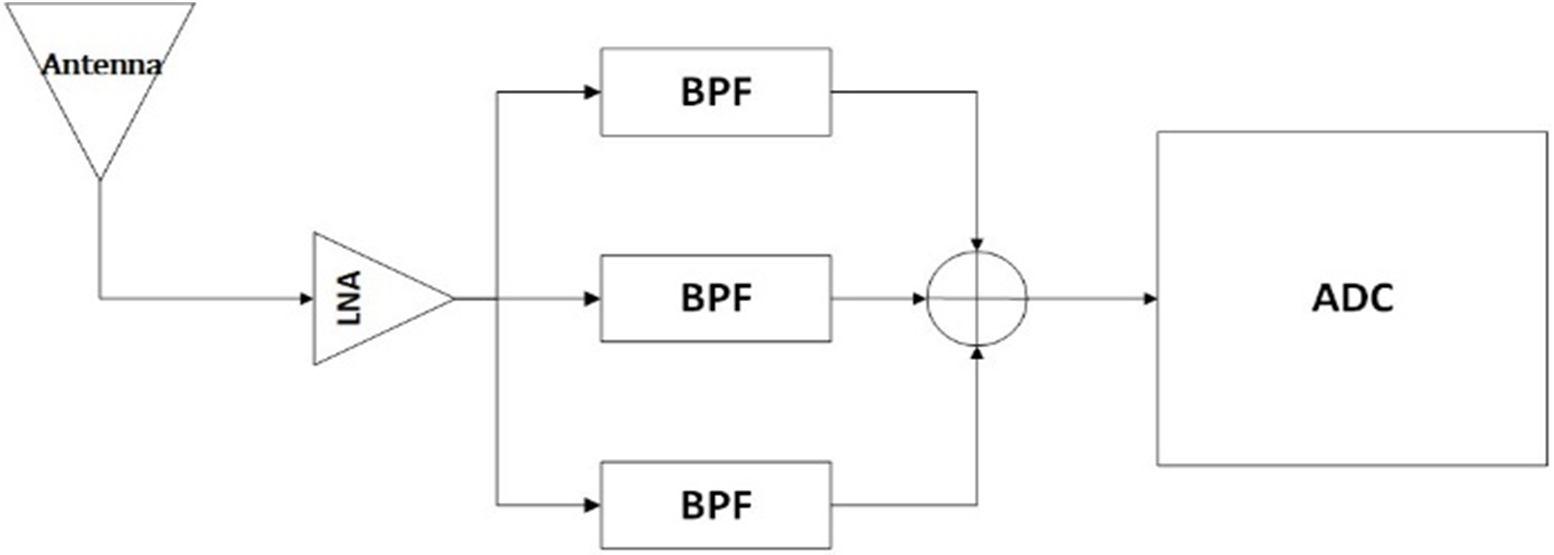
With the ongoing development in analog to digital converters, Direct RF sampling (DFRS) architecture became a candidate for Multi-GNSS RF receiver design DRFS architecture provides the opportunity to overcome the limitations of its precedent for simultaneous Multi-GNSS processing In the DRFS, the RF signal is sampled as early in the receiver RF Chain in case of single and multiple bands as shown in Fig. 2 and Fig. 3 .
The down-conversion of the high frequency GNSS signals occurs during the sampling process itself using signal aliasing in a regulated manner. Thus, removing the intermediate frequency (IF) stages of traditional receivers. DRFS simplifies the RF front-end as it does not need analog mixers which reduces the analog components, power consumption, cost, and size[3]. Furthermore, DRFS flexibility is regarded as very high because it samples the signal directly from radio frequencies (RF) as well as it handles multiple frequency bands with the same hardware simultaneously

ISSN: 2321-9653; IC Value: 45.98; SJ Impact Factor: 7.538 Volume 10 Issue XII Dec 2022- Available at www.ijraset.com
Nevertheless, DRFS receiver has its fair share of challenges, such as high power consumption due to the need of high amplification stages to reach full scale range of the ADC, high quality sampling process due to the high frequencies of the signals directly sampled[4] Additionally, down-converting the RF signal will generate noise folding caused by aliasing, hence decreasing the SNR These challenges are considered major research motive for the future improvement to increase the performance of DRFS receiver[5]
Fig. 1 The traditional superheterodyne receiver

Fig. 2 single-band direct RF sampling receiver.
Fig. 3 multiple-band direct RF sampling receiver

.
DRFS receiver has been discussed throughout literature by many authors such as [5]–[10] In 1996 Akos and Tsui [6] designed a DRFS prototype that was able to receive the GPS L1 C/A (null-null BW of 2 MHz) with a sampling frequency of 5 MHz and an acquisition code to process the data. In [8] Thor and Akos described a DRFS prototype that captured both GPS L1 C/A signal and GPS L3 at 1381.05MHz then sampled both with a sampling frequency of approximately 74 MHz, an FPGA is used to process the data then transmit it to a PC for post-processing.

ISSN: 2321-9653; IC Value: 45.98; SJ Impact Factor: 7.538 Volume 10 Issue XII Dec 2022- Available at www.ijraset.com
In [9] Psiaki proposed a DRFS prototype that receives the GPS C/A code and precision code (P(Y)) on the L1 and L2 frequencies then sampled with a sampling frequency of 55.5MHz ,the sampled data is transmitted to CPLD logic gates then saved and stored to computer to process it offline using MATLAB. In [5] Psiaki and Akos designed DRFS prototype to capture GPS L1 C/A has design to determine the effects of sample clock jitter with a sampling frequency 5.71429 MHz the sampled data is sent through a generic data acquisition system(DAQ), where it is stored on disk for offline processing. The most recent and advanced work on DRFS GNSS prototype is in [10] where Lamontagne proposed a flexible real time Direct RF sampling based GNSS receiver that can capture the GPS L1 C/A signal with a sampling frequency of 300 MHz, and it is used to validate the jitter effects and sampling jitter limits theoretical formulations so it does not affect the GNSS signal. Then the FPGA is used for data processing In this paper, we aim to present a complete theoretical framework for DRFS frontend receiver with focus on Multi-GNSS applications and use that framework for design optimization. That goal led us to consider two main issues: first, introducing an efficient and simplified frequency planning algorithm to determine all proper sampling frequencies for DRFS single and multiple RF signals Second, studying the noise folding effects and theoretically analyzing their relation to the sampling frequency and their impact on the DRFS system performance, SNR The paper is organized such that section II focuses on developing the mathematical constraints used to calculate the proper sampling frequencies in case of single and multiple RF signals, III presents the frequency planning and the MATLAB-coded single and multiple band algorithm to calculate proper sampling frequencies. IV studies the effects of noise folding on DRFS The single and multi-band DRFS algorithms are implemented on MATLAB for L1, L2, and L5 and their results are presented in V. The design optimization is presented in VI VII concludes the paper.
Fig. 4 (a) the original, (b) the sampled signal by sampling frequency (N=Odd) and (c) the sampled signal by sampling frequency (N=Even).


DRFS theory states that when a continuous bandpass signal of interest is sampled with a sampling frequency that is more than twice the signal’s bandwidth ( ≥2 ) that allows the reconstruction of the sampled signal at a much lower frequency than its original carrier frequency since the sampling requirements are based on the information bandwidth of the signal rather than the carrier frequency[7]
The sampling process based on the Direct sampling front end is depicted in Fig. 2. In the case of a single band and in the case of multiple bands. As shown in figures, the signal enters through the antenna, then it is processed by the low noise amplifier (LNA) that amplifies all the signals within its operational band. The amplified signals then pass through a bandpass filter that attenuates all signals outside the selected bands of interest, then it passes through the analog to digital convertor (ADC) where the selected bands of interest are sampled to a lower intermediate frequency (IF) with a sampling frequency that is selected based on the algorithm explained is sections III and III

ISSN: 2321-9653; IC Value: 45.98; SJ Impact Factor: 7.538 Volume 10 Issue XII Dec 2022- Available at www.ijraset.com


In the sampling theory when a signal is multiplied by a sampling signal its information bandwidth is replicated in frequency domain at an integer multiple of the sampling frequency , thereby creating an infinite number of replicas of the signal. The proper choice of the sampling frequency will create a replica that falls within therange from 0 to half the sampling frequency which is called the baseband Nyquist zone
When it comes to calculating the proper sampling frequencies there are some constraints that need to be considered[11]: 1) The sampling frequency should be at least twice the bandwidth of the signal ≥2 2) Choosing an that avoid any overlap between aliased bands from the negative and positive frequency spectrum and the baseband Nyquist zone lower end at 0 or upper end at 3) should be properly selected to minimize the noise folding. That aspect is discussed in section IV. Starting by considering a spectrum of a continuous bandpass signal with bandwidth , located between the positive lower frequency Hz and higher frequency Hz with a center frequency The negative frequency spectrum can be expressed as the interval ( , ) with a center frequency of The positive and negative spectrum of the bandpass signal are both shown in Fig. 4(a) In order to express the above mentioned constrains mathematically, we introduce an arbitrary positive integer that equals to the integer part of . can be either even or odd. If , we denote the sampling frequency as . In this case, the sampled positive frequency spectrum exists in +ve baseband Nyquist zone as shown in Fig. 4(b), whereas if , we denote the sampling frequency as . In this case, the sampled negative frequency spectrum in +ve baseband Nyquist zone thus shown inverted in Fig. 4 (c) The spectrum of the sampled signal as shown in Fig. 4(b)(c) for both types can be obtained by replicating the spectrum of the original signal at around . Accordingly, the spectrum of the original signal must not straddle for any integer , otherwise the sampled signal would be aliased[12] The mathematical expression for constrain 2 in the case of a single band sampling differs based on the value of (even or odd), where each case has its own expression that can be found from Error! Reference source not found. In the case of odd as shown in Fig. 4(b)., the expression is formed by considering that the lower frequency and higher frequency does not overlap with other replicas nor any of the two baseband Nyquist zone borders. The minimum and maximum sampling frequencies, using and respectively, can be expressed as: +( +1) >0 1 > 1a +( +1) < 2 2 < 2a As for the second case of when N is even, the minimum and maximum sampling frequencies using and can be expressed as: >0 3 < 2 3a > 4 < 2 2 +1 4a
Using DRFS shows that the RF signal centered at will be down-converted to an intermediate frequency In other words, thecentered bandpass signal will be replicated around at each (where is a non-zero positive integer) then we will obtain an that falls in the range of 0… The mathematical relationship between, , and can be expressed as: ⎩ ⎪ ⎨ ⎪ ⎧ ( , ) 2⁄ ( , ) 2⁄ 5 here ( , ) denotes the remainder of divided by [12]
ISSN: 2321-9653; IC Value: 45.98; SJ Impact Factor: 7.538 Volume 10 Issue XII Dec 2022- Available at www.ijraset.com

When multiple bandpass signals are to be sampled by the ADC, a straightforward solution is to increase the sampling frequency to accommodate the wider range of bandwidths that contain all the signals spectrums Unfortunately, this approach can be computationally expensive and demanding as shown by brown [13] where they utilized an 800MHz sampling frequency for L1 and L2 bands. Following the approach proposed in this paper, through considering DRFS theorem with a number of bandpass signals result in a significantly reduced sampling frequency that need to be greater than twice the sum of the signals bandwidths and fulfilling the DRFS associated constrains that are listed in A, hence a consequently reduced computational resources requirement Regarding the case of multiple bands, a searching algorithm is developed to find the proper sampling frequencies through introducing several filtering conditions that calculate the proper sampling frequencies of multiple RF signal For example, GPS L1, L2 and L5 sampling frequencies were calculated individually from the Single RF algorithm, then multiband overlapping conditions were implemented producing proper sampling frequencies for these multiple bands. These conditions are explained thoroughly in section B.
The sampled RF signal with all its replicas is represented in Fig. 4 and it is utilized to extract the mathematical constraints used in the single and multiple RF signal algorithm to calculate the proper sampling frequencies, which is implemented in MATLAB

In the case where the input to the ADC is a single RF signal, our first proposed algorithm implements the derived expressions (1)(5) on MATLAB to find its proper sampling frequencies The algorithm flow is shown in Fig. 5:
Step 1: Insert the single-band RF signal center frequency and bandwidth
Step 2: Calculate the lower ( ) and higher ( ) end frequencies of the bandpass signal bandwidth from the following equations: = 2 6 = + 2 7

Step 3: Start a loop with as a positive integer that starts at 0 up to . Within the loop, the lower and higher ranges of valid sampling frequencies ( , , , ) are calculated in two cases: in the case is odd the derived expressions (1), (2) are used. And in second case when is even expression (3), (4) are used.
Step 4: The aliased lower/higher intermediate frequencies ( , , , ) are calculated from expression (5) for both cases

Step 5: Finally, the output of the code is saved as an array, where each columns represents a specific value, the first column represents the values used then the next columns show the proper sampling frequencies ranges from , to , and its intermediate frequencies from , to , .
Fig. 5 Single-band Direct RF sampling algorithm flow.
ISSN: 2321-9653; IC Value: 45.98; SJ Impact Factor: 7.538

Volume 10 Issue XII Dec 2022- Available at www.ijraset.com

One of our main contributions is the simplified frequency planning algorithm in the case of multiple bands. The multi-band algorithm we developed and dramatically decreases the computational requirements compared to [9], [14], [15] It is considered to be a flexible, more robust way to find the proper sampling frequency ranges without the need to derive complicated mathematical expressions to define the multi-band second constraint unlike[12], [14], [15] and their complex solutions. The approach we took for our multi-band algorithm involves using a searching algorithm that finds the overlapping proper ranges and its corresponding through a few filtering conditions. These conditions filter the values calculated by the single-band algorithm for the individual bands Fig. 6 shows a clarification diagram for the algorithm and its steps.


Step 1: Insert the characteristics of the three RF signals, their center frequencies , and bandwidth where indicates the index of the RF single.
Step 2: The three bands proper values were calculated independently using the single band algorithm in section 0. The first filtering condition applied is following the Nyquist theorem where each obtained value that fall under twice the total bandwidth = + + are removed
Step 3: A loop is generated to filter all obtained values through comparing each ( , , , ) of each band with the other bands to remove values that are not overlapping between the bands. The first condition can be set where , should be higher than or equal to , and , , then it should also be lower or equal to , and , . Using several conditions for each band as previously explained will allow us to find overlapping , and , between all the three bands.
Step 4: The second filtering conditions within the loop indicates that the spacing between , , , 0 and . The intermediate frequencies of each band compared to the other should be bigger than half the total bandwidth of themselves, each lower end frequency ( /2) should be bigger than 0, and higher end frequency ( + /2) should be smaller than . These conditions are to make sure there is no aliasing occurring and remove the obtained sampling frequencies ( , , , ) that allow aliasing.
Step 6: The sampled data is saved into an array that contains the odd and even integers , , , and sampling frequencies , to , . The experimental results of both algorithms are demonstrated in the Results V
Noise folding is defined as the accumulation of noise from aliased frequencies on top of the desired band of interest at because of the sampling process where the spectrum shifting occurs as shown in Fig. 7[16] The total noise that gets folded is mainly generated by the hardware components of the receiver in the out of band and aliased to in band and this noise is known to be an Additive White Gaussian Noise (AWGN) [16]

ISSN: 2321-9653; IC Value: 45.98; SJ Impact Factor: 7.538 Volume 10 Issue XII Dec 2022- Available at www.ijraset.com
Noise folding is an important factor in DRFS receiver design as using a low sampling frequency will increase the amount of noise folding and that decreases the SNR while increasing the sampling frequency will enhance the SNR but will require more computational resources for DSP. This tradeoff (Of ) between the computational resources requirements and the SNR is inevitable, the best solution is to find a middle ground for proper sampling frequency with an acceptable SNR[7]

The aliased noise gets added to one another creating a noise of times the noise floor in the Nyquist band in both negative and positive frequencies as shown in Fig. 8. is the integer mentioned in sections II.

To calculate the resultant noise folding we can consider the as in-band noise, as out of band noise and as a sampling integer. Mathematically, we quantify that the total noise to be considered is: + = +2( 1) 8
Knowing that the sampled signal is going to suffer from noise aliasing, it is very essential to have a bandpass filter prior to theADC. The typical SAW filter can reduce the out of band noise by 40-60 dB depending on the bandwidth. For example, if = 300MHz used to sample a GPS L1 signal, the spectrum is folded 5 times, so N=5, which is an increase of almost 6dB in noise.
To demonstrate and prove the proposed method of DRFS, we conducted two experiments one for the single-band algorithm and the second for multi-band algorithm on MATLAB based on the DRFS receiver theory with GPS bands signals , ,and [17], the proper frequency ranges obtained are then plotted to verify that there is no aliasing or overlapping caused by the them.
For single band algorithm in sections 0, we used one of the GPS- band signal that has carrier frequency =1575.42 , bandwidth =15 [18]. The signal is bounded between 1567.92 and 1582.92 , the proper sampling frequencies are extracted by the algorithm and shown in TABLE I.

ISSN: 2321-9653; IC Value: 45.98; SJ Impact Factor: 7.538 Volume 10 Issue XII Dec 2022- Available at www.ijraset.com

TABLE I
GPS L1 band proper sampling frequencies obtained from single-band algorithm N , , 52 30.1508 MHz 30.1523 MHz 51 30.440 MHz 30.445 MHz 50 31.03MHz 31.047MHz 49 31.6584 MHz 31.675e MHz 48 32.637 MHz 32.665 MHz 47 32.9775 MHz 33.0088 MHz . . . 5 287.803MHz 313.584MHz 4 316.584MHz 348.426MHz 3 452.262 MHz 522.64 MHz 2 527.64MHz 627.168 MHz 1 1.05528GHz 1.56792 GHz
Fig. 9 plot of a sampled bandpass signal using one of the values in TABLE I
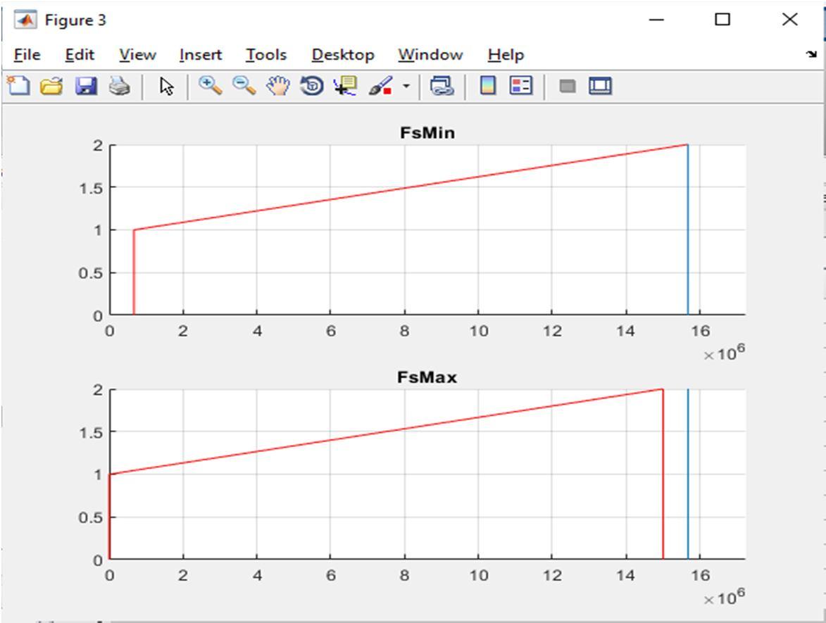
The outcome of the algorithm is used to plot the resultant spectrum of the sampled signals and the constraints of the A is checked to be fulfilled. The validity of this check is depicted in Fig. 9, where the range from , = 3103 , =31047 is used on the GPS L1
For multiple-band algorithm, we considered 3 GNSS signals in GNSS bands ( , , ) with their carrier frequencies = 157542 , =12276 , =117645 and bandwidth =15 , =11 =125 [18] The algorithm in section B is used to extract the proper sampling frequencies for these three bands individually, we can find several proper sampling ranges in , indicating that the ( , , , ) values showed be ≥76 .

ISSN: 2321-9653; IC Value: 45.98; SJ Impact Factor: 7.538 Volume 10 Issue XII Dec 2022- Available at www.ijraset.com

Table II. The of GPS bands ( , , ) equals to 38 , indicating that the ( , , , ) values showed be ≥76 .

Table II
Some GPS L1, L2 and L5 bands proper sampling frequencies obtained from Mutli-band algorithm , ,
10 8 7 151.7542MHz 151.7625 MHz 9 7 7 158.292 MHz 158.95 MHz 7 5 5 221.036 MHz 222.2 MHz 6 5 5 226.131 MHz 231.040 MHz 3 2 2 493.24MHz 522.64 MHz 2 2 2 527.64MHz 585.10 MHz 2 2 1 591.35 MHz 611.05 MHz 2 1 1 633.168MHz 780.13MHz 1 1 1 1.05528 GHz 1.1702 GHz
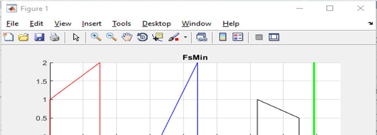
Fig. 10 plot of three bands sampled bandpass signals using one of the values extracted in
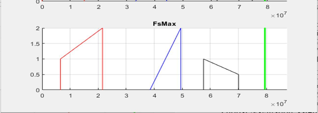
Table II.
The outcome of the Multi-band algorithem in B is used to plot the resultant spectrum of the sampled signals (GPS L1,L2, and L5) which prove the validity of the algorithem as depeicated in Fig. 10 where ranges from 151.7542MHz to 151.7625 MHz is used from Table II.
ISSN: 2321-9653; IC Value: 45.98; SJ Impact Factor: 7.538 Volume 10 Issue XII Dec 2022- Available at www.ijraset.com

Following the framework of designing a DRFS receiver, an optimized sampling frequency selection process and its effect on signal to noise ratio (SNR) through minimizing the complexity and computational requirement of design was proven. A mathematical derivation conducted on direct RF sampling technique; we were able to calculate the optimal Fs values in the single band and multiple-bands case. Some values were tested on the DRFS architecture on Fig. 3. Starting by selecting the sampling frequency of 300MHz in both single band and multiple-band cases. Finally, following the noise folding equation (8) we were able to minimize this effect by adding a bandpass filter prior to the ADC’s sampling process. Sampling the GPS L1 band single for example, using a 300MHz sampling frequency will fold the signal to N=5 folds as provided in A producing a noise of 6 dB which is considered a low noise effect.
A complete theoretical framework for a DRFS front-end receiver has been presented. A straightforward algorithm for frequency planning in case of receiving three bandpass signals simultaneously has been proposed. The frequency planning algorithm had been applied to the case of a multi-GNSS receiver that is considering L1, L2, and L5 bands and results is shown and confirmed. The proposed algorithm is implemented using MATLAB and dramatically decreases the computational complexity and simplifies the implementation compared to previous algorithms [7], [11], [12], [12], [19]. Furthermore, the amount of noise folding ( ) is theoretically derived and mathematically expressed which is an essential step needed for the optimal selection of and compromising between the needed computational resources (in the DSP stage after the RF front-end) and the receiver Signal-ToNoise Ratio (SNR). In conclusion following the framework presented in this paper for design optimization would be a new step into designing a fully operational DRFS front-end receiver
The authors wish to extend their sincere gratitude to EHSIM (Elektronik Harp Sistemleri Mühendislik Ticaret Anonim Şirketi) for supporting this project and research work.
[1] W. Lechner and S. Baumann, Global navigation satellite systems, vol. 25, no. 1–2. 2000.
[2] J. Ó. Winkel, “Modeling and Simulating GNSS Signal Structures and Receivers,” Thesis, pp. 1–247, 2000.
[3] M. R. Naik and C. H. Vithalani, “THE SOFTWARE-DEFINED RADIO IS NOW A REALITY,” 2013. Accessed: May 19, 2021. [Online]. Available: www.ijareeie.com.

[4] V. Syrjälä, M. Valkama, and M. Renfors, “Design considerations for direct RF sampling receiver in GNSS environment,” 5th Work. Positioning, Navig. Commun. 2008, WPNC’08, vol. 2008, pp. 9–13, 2008, doi: 10.1109/WPNC.2008.4510351.
[5] M. L. Psiaki, D. M. Akos, and J. Thor, “A comparison of direct radio frequency sampling and conventional GNSS receiver architectures,” Navig. J. Inst. Navig., vol. 52, no. 2, pp. 71–81, 2005, doi: 10.1002/j.2161-4296.2005.tb01733.x.
[6] D. M. Akos and J. B. Y. Tsui, “Design and implementation of a direct digitization GPS receiver front end,” IEEE Trans. Microw. Theory Tech., vol. 44, no. 12 PART 2, pp. 2334–2339, 1996, doi: 10.1109/22.554550.
[7] D. M. Akos, M. Stockmaster, J. B. Y. Tsui, and J. Caschera, “Direct bandpass sampling of multiple distinct RF signals,” IEEE Trans. Commun., vol. 47, no. 7, pp. 983–988, 1999, doi: 10.1109/26.774848.
[8] J. Thor and D. M. Akos, “A direct RF sampling multifrequency GPS receiver,” in Record - IEEE PLANS, Position Location and Navigation Symposium, 2002, pp. 44–51, doi: 10.1109/plans.2002.998887.
[9] M. L. Psiaki, S. P. Powell, H. Jung, and P. M. Kintner, “Design and practical implementation of multifrequency RF front ends using direct RF sampling,” IEEE Trans. Microw. Theory Tech., vol. 53, no. 10, pp. 3082–3089, 2005, doi: 10.1109/TMTT.2005.855127.
[10] G. Lamontagne, R. J. Landry, and A. B. Kouki, “Direct RF Sampling GNSS Receiver Design and Jitter Analysis,” Positioning, vol. 03, no. 04, pp. 46–61, 2012, doi: 10.4236/pos.2012.34007.
[11] R. G. Lyons, Understanding Digital Signal Processing, Second Edition. Prentice Hall PIR, 2004.
[12] J. C. Liu, “Complex bandpass sampling and direct downconversion of multiband analytic signals,” Signal Processing, vol. 90, no. 2, pp. 504–512, 2010, doi: 10.1016/j.sigpro.2009.07.017.
[13] A. Brown and B. Wolt, “Digital L-band receiver architecture with direct RF sampling,” Rec. - IEEE PLANS, Position Locat. Navig. Symp., pp. 209–216, 1994, doi: 10.1109/PLANS.1994.303406.
[14] M. Choe and K. Kim, “Bandpass sampling algorithm with normal and inverse placements for multiple RF signals,” IEICE Trans. Commun., vol. E88-B, no. 2, pp. 754–757, 2005, doi: 10.1093/ietcom/E88-B.2.754.
[15] C. H. Tseng and S. C. Chou, “Direct downconversion of multiband RF signals using bandpass sampling,” IEEE Trans. Wirel. Commun., vol. 5, no. 1, pp. 72–76, 2006, doi: 10.1109/TWC.2006.1576530.
[16] V. Mookiah, “Quadrature BandPass Sampling Front-end for Global Navigation Satellite Systems,” no. July, 2015.

ISSN: 2321-9653; IC Value: 45.98; SJ Impact Factor: 7.538 Volume 10 Issue XII Dec 2022- Available at www.ijraset.com
[17] J. Subirana, J. Zornoza, and M. Hernández-Pajares, Gnss Data Processing, vol. II. 2013.
[18] E. A. Sholarin and J. L. Awange, “Global navigation satellite system (GNSS),” Environ. Sci. Eng. (Subseries Environ. Sci., no. 9783319276496, pp. 177–212, 2015, doi: 10.1007/978-3-319-27651-9_9.
[19] W. Li and Z. Liu, “A bandpass sampling design in multi-channel radio Receiver,” Procedia Environ. Sci., vol. 11, no. PART A, pp. 250–255, 2011, doi: 10.1016/j.proenv.2011.12.039.

