
11 I January 2023 https://doi.org/10.22214/ijraset.2023.48536
ISSN: 2321-9653; IC Value: 45.98; SJ Impact Factor: 7.538
Volume 11 Issue I Jan 2023- Available at www.ijraset.com

ISSN: 2321-9653; IC Value: 45.98; SJ Impact Factor: 7.538
Volume 11 Issue I Jan 2023- Available at www.ijraset.com

Abstract: During adsorption cycles, the simulations of thermal effects play a significant role in designing adsorption-based systems such as gas separation, gas storage and heat pumps. This paper presents the two-dimensional axisymmetric model of a hydrogen storage tank on activated carbon at a particular temperature and pressure range using User Defined Functions in Fluent (UDF). The adsorption model used for CFD analysis is based on mass, momentum and energy equations and the modified form of Dubinin-Astakhov model. The simulation is implemented through Ansys Fluent. The Linear Driving Force is applied to study the cryo-adsorption kinetics. The results are varied from pipe inlet to the tank wall based on mass flux at different flow times. The pressure and temperature profile inside the system for different inlet conditions is studied in detail. The profiles of pressure and temperature are plotted at different time intervals. The velocity distribution at various time intervals is presented for charging and discharging of hydrogen adsorption Moreover, the results are compared with the model parameters of carbon and steel by varying the thermal conductivities and specific heat capacities. The results obtained for the pressure and temperature profile shows a good agreement with the other results available in the literature.
Keywords: Adsorption, Gas separation, User Defined Functions, Dubinin-Astakhov model, Linear Driving Force
A finite control volume (FCV) approach using ANSYS fluent software is used in this study to simulate the hydrogen adsorption process during charging, dormancy, and discharging with liquid nitrogen cooling. Models for the Dubinin-Astakhov (DA) adsorption isotherms and the adsorption kinetics are two examples of the adsorption sub-models employed in this study. In this investigation, the isosteric heat of adsorption is constant. An alternative source to the current fossil fuel-based energy system, a hydrogen energy vector, has been proposed to solve problems pertaining to environmental and energy distribution issues. A considerable amount of literature over the past few years deal with hydrogen storage, in which this remains an interesting research domain due to its low volumetric energy density under ambient conditions. Hydrogen can be stored in adsorbed/absorbed gas and liquid phases. So, there are four ways of storing hydrogen namely compression, liquefaction, adsorption in high surface nanoporous materials and metal hydrides [1]. Nanoporous materials which have high surface area such as activated carbon has been chosen as a storage media for hydrogen due to its light weight, reliability, safety, efficiency and low-cost adsorption material. Experimental and simulation studies have been carried out on the charging process of hydrogen storage tank in a packed bed of activated carbon at room temperatures. The adsorption of hydrogen on activated carbon in a steel container at a pressure of 10 MPa and temperature of 295 K has been simulated by [2]. However, the discharging and dormancy process was not considered in their simulation. The design of efficient systems must take into account the heat generated and energy effects associated with the adsorption process. The sorption characteristics in the micro-nanopores can be illustrated by the micropore filling theory. In a general perspective, it is credited that the pore size and the radius of curvature don’t alter the sorption characteristics of gas molecules in relatively large pores. However, “capillary condensation” transpires in gas molecules under supercritical conditions. In this case, the single-layer or multi-layer sorption theory cannot portray the existing state of gas in pores. Therefore, the shortcomings of the single-layer or multilayer sorption theory can be concocted by the micropore filling theory [3,4]. The sorption characteristics of hydrogen and methane in high-surface activated carbon were deliberated by [5,6,7]
In order to define the adsorbed phases in energy and mass balance equations, a proper functional representation of the adsorption data of the system is necessary. The fitting of modelled data of adsorption isotherm to experimental data determines the pressure and temperature dependent operating parameters. Hence, the understanding of fitting accuracy is critical for adsorbate or adsorbent systems using thermodynamic simulations.
ISSN: 2321-9653; IC Value: 45.98; SJ Impact Factor: 7.538 Volume 11 Issue I Jan 2023- Available at www.ijraset.com
The modelling of adsorption in microporous adsorbent at high ranges of pressure and supercritical temperatures has been thoroughly studied which is based on excess adsorption and Dubinin-Astakhov (D-A) model [8]. The energy and mass balance equations have been established for adsorption of hydrogen on activated carbon over a wide range of operating conditions in the supercritical region. The assumption of the perfect gas is discussed instead of a specific volume of the adsorbed phase for the evaluation of thermodynamic properties. The adsorption isotherms for gas as a function of pressure and temperature obtain the adsorbed phase distribution in the balance equations. For this purpose, the modelling of excess hydrogen adsorption isotherms has been adapted from the Dubinin-Astakhov (D-A) model at high pressure and over a wide range of supercritical temperatures. The objective of this work is to simulate the hydrogen adsorption on activated carbon computationally from charging to discharging and research the variations of temperature and pressure at various time intervals. The CFD model is based on mass, momentum, and energy equations and adsorbed hydrogen in a steel tank wall. The adsorption model is based on a modified Dubinin-Astakhov (D-A) adsorption equation. This paper focuses on the study of hydrogen storage tank's temperature and pressure variations by considering the impact of heat capacity and thermal conductivity of carbon and steel wall as a function of temperature. The User Defined Functions are hooked into the Fluent software to modify the energy and mass equations and to set the boundary conditions. This paper is organized according to different sections. Section II describes modelling of the hydrogen adsorption. The geometry model and parameters are given in Section III. Section IV presents results on the charging and discharging process for hydrogen adsorption. Finally, the conclusion part is presented in Section V.
The subcritical gas pore filling in microporous adsorbents in activated carbons has been specifically tailored to the DubininAstakhov (D-A) model. The following expression gives the absolute adsorption isotherm:
(1) The maximum amount of adsorption, n max, is expressed in mol kg-1, R is the universal gas constant, which is equal to 8.314 J mol kg-1, most activated carbons like to have m set to 2, and P 0 and P are the saturation pressure (1470 MPa) and equilibrium pressure, respectively. The sum of an enthalpic factor (3080 J mole -1) and an entropic component (T), is known as the temperature-dependent characteristic free energy term (18.9 J mol -1 K -1). T (2) In the charging state, the hydrogen crosses from the gas phase towards the adsorbed phase, whereas in the discharging state, it comes from the adsorbed to the gas phase. In order to characterize the phase transition, a mass conservation equation must include the mass source term. The term "mass source" is written as follows: 1 mbp SMnt (3) where εb is the bed porosity, ρp is the activated carbon particle density (kg m -3) and M is the molecular mass of hydrogen. The factor nt is calculated by the Linear Driving Force model. The adsorption rate of LDF is given as: a ntknn (4) where k is the mass transfer coefficient, with a value of 0.45 s-1, and na is the absolute adsorption determined by the D-A model, respectively. Refer to Eq. (4) which can be transformed into Eq. (5) by finite difference method.
The energy source term of the energy conservation equation can be expressed as: hm SHSM (6) The heat of adsorption is obtained by the following equation: max ln a Hnn (7)
ISSN: 2321-9653; IC Value: 45.98; SJ Impact Factor: 7.538 Volume 11 Issue I Jan 2023- Available at www.ijraset.com
The inlet temperature of the hydrogen gas is maintained at 301.5 K during charging in this work. 49000 Pa and 301.5 K are the initial pressure and temperature settings, respectively. It is considered that the heat transfer coefficient is 36 Wm-2 K-1 .
Figure 1 (a) and (b) demonstrate the geometry model and meshing of the hydrogen tank, respectively. The pipe is symbolized by the grey area, and the activated carbon is enclosed in a steel-walled tank in the tank. There are 94105 nodes in the grid of the hydrogen storage tank. Here, a quadrilateral mesh is taken into account. In the very first case, the model parameters are considered constant for specific heat capacity and thermal conductivity of steel wall and activated carbon. The specific heat capacities are 820 J kg-1 K-1 and 460 J kg-1 K-1 for activated carbon and steel wall respectively and the thermal conductivity of activated carbons is 0.646 W m-1 K-1 Table 1 lists the model dimensions. Table 2 depicts the thermal characteristics of steel and hydrogen activated carbon [9] (a) (b) Fig. 1. a) The geometry and b) mesh of the hydrogen storage tank Table 1. The Model Parameters Tank inner radius 46.9 Pipe inner radius 3.8 Tank length 350 Pipe length 50 Tank wall thickness 3.9 Pipe wall thickness 1 Table 2. Thermal Properties of hydrogen, Activated Carbon and Steel
ISSN: 2321-9653; IC Value: 45.98; SJ Impact Factor: 7.538 Volume 11 Issue I Jan 2023- Available at www.ijraset.com
The sharp rise of storage tank pressure is observed in Fig. 2 and this pressure reaches the maximum at the end of charging. When the hydrogen is adsorbed and compressed, a considerable amount of heat is released, which leads to a quick rise in temperature and pressure. The pressure drops slightly during the stage of dormancy. This is due to the decrease in temperature as the heat is transferred between the outside and the hydrogen storage tank, which ultimately results in pressure reduction. During the dormancy stage, the pressure drops sharply and reaches the minimum value at the end of discharge. The rapid decline of pressure occurs due to a decrease in the amount of gaseous hydrogen and the absorption of a large amount of heat in the hydrogen storage tank.
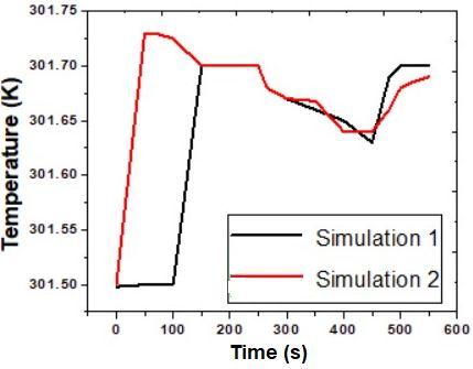
The comparison of pressure obtained from simulation 1 (constant thermal conductivities and heat capacities of carbon and steel wall) with simulation 2 (varying heat capacity and thermal conductivity of carbon as well as heat capacity of steel wall) at different time is shown in Fig. 3. This figure depicts the accurate representation pressure owing to varying specific heats as a function of temperature. In general, simulation 2 shows good agreement with the simulation 1. The peak pressure is reached at the end of charging. The decrease in pressure is observed during the dormancy stage. The pressure drops slightly during the stage of dormancy. This is due to the temperature drop as the heat transfer occurs between the outside and the hydrogen storage tank.
During the dormancy stage, the heat transfer between the heat transfer coefficients of steel wall and environment are closely related. Also, the thermal conductivities of hydrogen and activated are closely linked. The tank heat convection and transfer of heat with the environment is mainly related by the temperatures in the axial direction, while the thermal conductivity is mainly by the temperatures in the radial direction. The contribution of the heat transfer coefficient is limited, so an accurate value of thermal conductivity has been taken in consideration. It is obvious that temperature at the inlet is maximum than temperature at central positions as revealed from Fig. 4.
ISSN: 2321-9653; IC Value: 45.98; SJ Impact Factor: 7.538 Volume 11 Issue I Jan 2023- Available at www.ijraset.com
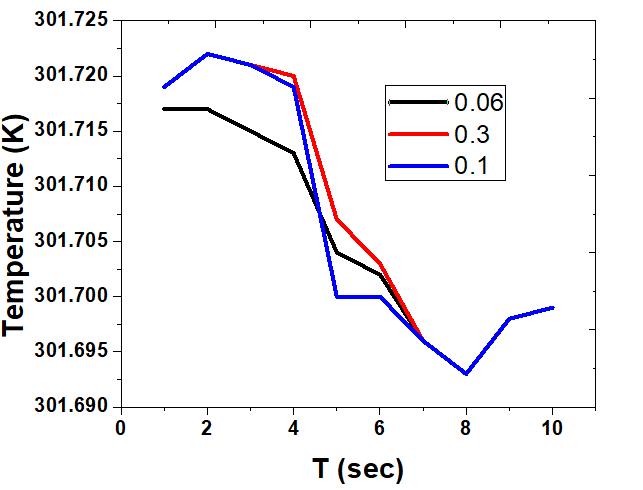
The simulation of temperature at different points is shown in Fig. 5. The heat transfer in the central area is relatively slow because it is far away from the wall. Meanwhile, the tank temperature is somewhat higher than that of charging hydrogen, that is why the charging hydrogen have a cooling effect to some extent. A better cooling effect is observed at the entrance. At the end of the charging, the temperature at point 0.1 m from the pipe inlet is the highest, and its difference with point 0.06 m is quite small. The highest temperature at 0.1 m from the inlet is achieved at 301.722 K during the charging process (2 seconds). The lowest temperature is 301.693 which is found at the end of discharging (8 seconds). With the adsorption and compression of hydrogen gas, a considerable amount of heat is released during the charging stage. The temperature rises at a distance of 0.06 m from the inlet is small because it is near the entrance and therefore, fresh filled hydrogen cools the area. The temperature at other points rises sharply during the process of charging. In the subsequent stages of dormancy, the temperatures at each point decrease sharply due to the large requirement of heat for the desorption and expansion process. The rise in temperature is observed which arises from a heat transfer between the hydrogen storage tank and outside after the discharging. The addition of porous media into the tank leads to an increase in compression work and flow resistance especially at the charging stage. The amount of adsorbed hydrogen is more compared to that of compressed gaseous hydrogen. The temperature at 0.1 m is more than at 0.06 from the inlet during the charging period due to the enhanced compression of the gaseous hydrogen. At a distance of 0.3 m from the pipe inlet, the temperature is almost close to the temperature at 0.1 m from the pipe inlet. This is due to the fact that both the points are close to the tank wall.
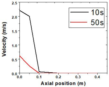
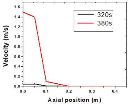
The charging and discharging of hydrogen adsorption is represented by velocity distribution along axial position at different time intervals is shown in Fig. 6 respectively. The velocity magnitude is maximum near the entrance and it tends to become uniform throughout the tank axial positions.
ISSN: 2321-9653; IC Value: 45.98; SJ Impact Factor: 7.538 Volume 11 Issue I Jan 2023- Available at www.ijraset.com
The present work is based on the simulation of adsorption of hydrogen in an activated carbon tank. The geometric model is an axisymmetric one and the mass flux profile is established at the inlet with the help of User defined Functions. During the discharging process, the temperature at the central region is lower than that of the temperature of the central region during the charging process. During the charging period, the pressure increases sharply between one and four seconds then it drops slightly during the dormancy period. At the end of the discharging, the pressure reaches a minimum value. The adsorption amount is higher than that of the compression amount for gaseous hydrogen. The results for pressure and temperature profile are in a good approximation with the fluent data from the literature. Further work on this area will achieve great progress by considering the effect of the porosity of packed bed during charging and discharging of adsorbed hydrogen. The cryo-adsorptive hydrogen storage system can be optimised using the model. Further research on the cryo-adsorption system should focus on the role that adsorbed phase hydrogen has effective thermal conductivity and its application of nonlinear adsorption heat using FLUENT software.
[1] G Hermosilla-Lara, G Momen, PH Marty, PL Neindre, K Hassouni, “Hydrogen storage by adsorption on activated carbon: investigation of the thermal effects during the charging process”, International Journal of Hydrogen Energy. Volume 32, pp. 1542-1553, 2007.
[2] JS Xiao, L Tong, CH Deng, P Benard, R Chahine, “Simulation of heat and mass transfer in activated carbon tank for hydrogen storage”, International Journal of Hydrogen Energy. Volume 35, pp. 8106-8116, 2010.
[3] MM Dubinin. Adv, “Porous structure of adsorbents and catalysts”, Colloid Interface Science, Volume 2, pp. 217– 235, 1968.
[4] MM Dubinin, VA Astakhov, “Development of the concepts of volume filling of micropores in the adsorption of gases and vapors by microporous adsorbents”, Russian Chemical Bulletin Volume 20, pp. 8– 12, 1971.
[5] L Zhou, Y Zhou, M Li, P Chen, Y Wang, “Investigation of the isosteric heat of adsorption for supercritical methane on shale under high pressure Langmuir”, Volume 16, pp. 5955– 5959, 2000.
[6] M Sudibandriyo, “High Pressure Sorption of Methane and Hydrogen at 25 C on Activated Carbons Prepared from Coal and Coconut Shell”, International Journal of Engineering and Technology Technol, Volume 11, pp. 79– 85, 2011.
[7] BU Choi, DK Choi, YW Lee, BK Lee, SH Kim, “Adsorption equilibria of methane, ethane, ethylene, nitrogen, and hydrogen onto activated carbon”, Journal of Chemical and Engineering Data, Volume 48, pp. 603– 607, 2003.
[8] MA Richard, P Benard, R Chahine, “Gas adsorption process in activated carbon over a wide temperature range above the critical point Part 1: modified Dubinin-Astakhov model Adsorption”, Volume 15, pp. 43-51, 2009.
[9] JS Xiao, L Tong, D Cossement, P Benard, R Chahine, “CFD simulation for chargeedischarge cycle of cryo-adsorptive hydrogen storage on activated carbon”, International Journal of Hydrogen Energy. Volume 37, pp. 12893-12904, 2012.