10 X October 2022 https://doi.org/10.22214/ijraset.2022.47242
ISSN: 2321 9653; IC Value: 45.98; SJ Impact Factor: 7.538

Volume 10 Issue X Oct 2022 Available at www.ijraset.com

ISSN: 2321 9653; IC Value: 45.98; SJ Impact Factor: 7.538
Volume 10 Issue X Oct 2022 Available at www.ijraset.com
1
2
Abstract: In this never ending quest for finding an alternative or a solution to the current problems related to increasing energy demands and climate change, various research, progress and development have been made in the subject of environmentally friendly energy systems. On one aspect the conversion of water into hydrogen gas and oxygen gas by using electro chemical process is an ideal method which can produce a clean and green fuel via: Sustainable methods and fossil free path ways. Hydrogen production by means of using various renewable energy sources such as solar energy, wind energy, tidal energy and hydro energy is a way to eliminate dependency of three systems on the electric grid. In this study which is based on a technique in which a fuel cell (ox hydrogen electrolyzer) is connected to a Photovoltaic solar panel to produce clean hydrogen and oxygen gas as a fuel. The objective of this project was to develop a strategy and make this generation process independent of other energy sources. A DC converter is used in such a sequence which can control and supply maximum power to the electrolytic cell which is connected to the solar Photovoltaic panel, which in turn we can obtain maximum hydrogen gas. Also, various catalysts which are most commonly found or easily available in the market are experimented in this research to get optimum output. The converter and voltage regulator is also responsible for operating the electrolytic cell in its optimum functioning region to avoid over heating of the cell. The DC converter and the Electrolytic cell has been tested and simulated within indoor and outdoor conditions. Analysis of this setup based on maximum power tracking showed 85% efficiency.
Keywords: Electrolysis of water, Green Hydrogen & Oxygen gas, Solar Powered
The conventional fuels which we are using today will eventually run out, so we need alternative sources of energy for our needs. Conventional fuels create a lot of pollution but hydrogen gas is a clean fuel [1] [3]. It does not produce any harmful gases or by products after burning. Hydrogen gas produced in large quantities can be compressed safely after purification. This compressed gas can be stored in the tanks occupying lesser area for further use as a fuel or to generate back electricity. As for now hydrogen production is mostly done from fossil fuel which results in carbon emissions [2]. So, hydrogen via solar energy has no harmful emissions or byproducts Oxygen will be obtained in the process and can be used for medicinal uses after filtering and purification. Thus, our project aims to create clean hydrogen and oxygen from electrolysis of water using the electricity generated from Photovoltaic solar panels. However, hydrogen generation by electrolysis of water has a share of only 4% in global production as electricity cost is the largest fraction of the production cost [2]
Electrical current runs through the electrolyte when a specific voltage is given to the electrodes, and water splits into hydrogen and oxygen at the cathode and anode electrodes, respectively. The lowest voltage required for water breakdown is 1.23 V, but in practice, more voltage is required to overcome system inefficiencies; this additional voltage is referred to as over potential. Electrical current runs through the electrolyte when a specific voltage is given to the electrodes, and water splits into hydrogen and oxygen at the cathode and anode electrodes, respectively. The lowest voltage required for water breakdown is 1.23 V, but in practice, more voltage is required to overcome system inefficiencies; this additional voltage is referred to as over potential [3] [4].
A redox reaction occurs mainly in pure water at the cathode which is negatively charged, with electrons being delivered to hydrogen cations to generate hydrogen gas. Similarly, on the other part an oxidation reaction happens at the anode which is positively charged, generates oxygen gas and supplying electrons to the anode [5].
The equation is as follows: “Cathode (reduction): 2 H2O (l) + 2e− → H2 (g) + 2 OH− (aq) Anode (oxidation): 2 OH− (aq) → 1/2 O2 (g) + H2O (l) + 2 e−”

ISSN: 2321 9653; IC Value: 45.98; SJ Impact Factor: 7.538
Volume 10 Issue X Oct 2022 Available at www.ijraset.com
The objective here is to:
1) Fabricate a solar PV based water electrolysis system to generate hydrogen and oxygen
2) Research and development in its storage
3) Research as using hydrogen as a fuel cell
4) Experiment and analyze injection of hydrogen or blending of hydrogen in various fossil fuels used in IC engines
5) Research and analyze domestic use of hydrogen
For fabrication of the hydrogen fuel cell we felt that these were the ideal materials which could be used. Also, by keeping a point in mind that it doesn’t react with the solution or fail under working condition or various external factors affecting the cell.
1) Acrylic sheet used for end plate
2) EPDM Rubber for the gasket or rubber rings
3) 316 Stainless Steel for Anode & Cathode
4) 3D printed disk (polycarbonate) separator
5) Polyurethane pipes supply of solution and gas from the fuel cell
6) Elbows, pipe joints, reducers, valves, etc.
B. Stack Assembly
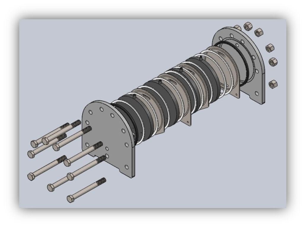
1) Screw 9 bolts into the end of the acrylic plate and secure it to a bench.
2) Then place the rubber ring or the silicon ring to the inner side of the plate
3) Then place the SS 316 metal plate on top
4) After that place another rubber ring on top of that
5) Place the 3D printed part on top of the metal plate
6) (This is the completion of one cell)
7) Then place a rubber ring
8) Similarly, on top of the rubber ring place the metal plate
9) Again, place the rubber ring on top of the metal plate and then place the 3D printed part. (This completes 2 cells which make one stack)
Fuel cell stacks with total 4 cells were built to generate and separate hydrogen and oxygen by using electricity. The system uses a DC power supply. The negative terminal of the system is connected to the cathode of the fuel cell. Similarly, the positive side of the power supply is connected to the anode or the positive terminal of the fuel cell [7].
ISSN: 2321 9653; IC Value: 45.98; SJ Impact Factor: 7.538 Volume 10 Issue X Oct 2022 Available at www.ijraset.com
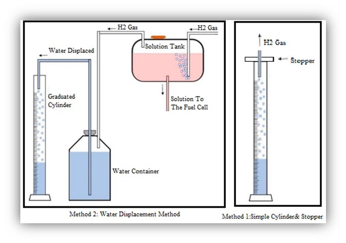
The solution is added to the 2 containers which are provided, each for oxygen gas and Hydrogen gas. This solution is made to flow through the pipes into the fuel cell. The stacking of the cell is made in such a manner as per the requirement or the quantity of the gas required. One anode and one cathode plate are linked to the positive and negative terminals of the power supply in a single stack. On the positive side (anode) we will observe oxygen gas forming, similarly on the negative side we can observe hydrogen gas forming. The quantity of hydrogen gas which is generated per unit time is directly proportional to the current flowing through the electrolyte [6]. The gas which is generated on the side of anode and the cathode is separated by the solid 3D printed disk which does not allow the gas to mix. The accumulated gas is taken out from the nozzle on top of this 3D printed disk. The gas can be further stored or passed for purification process and used later.
To understand the basic concept and to study the reactions by using various chemicals and their outputs along with their byproducts, we constructed a Hoffman’s voltammeter. It is commonly used as a small scale electrolytic cell, in our experimental investigation and understanding. It is made up of three upright cylinders that are connected together. Water and electrolyte can be added through the top of the inner cylinder. Platinum, graphite, and other noble metals are commonly used. Instead, we used stainless steel rods 316 and 316L
At the bottom of each of the two side cylinders, the electrode is connected to the positive and negative terminals of an electrical source. When electricity is conducted through the Hoffman volt ammeter, gaseous oxygen develops at the anode (positive) and gaseous hydrogen forms at the cathode (negative). Each gas bubble generated on the plate displaces water, which accumulates in the above two outer tubes, where a stopcock can be used to remove it.
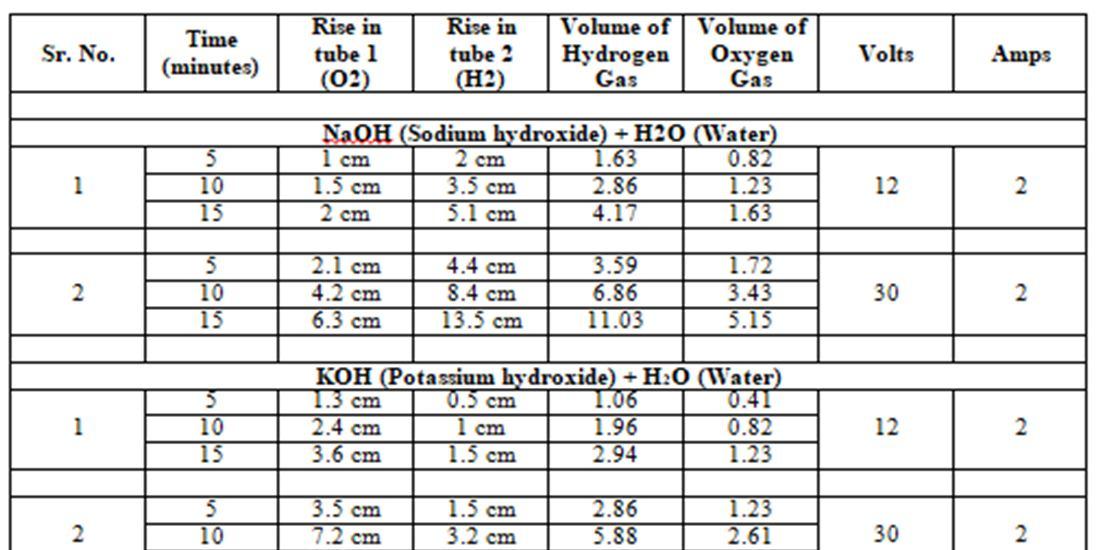
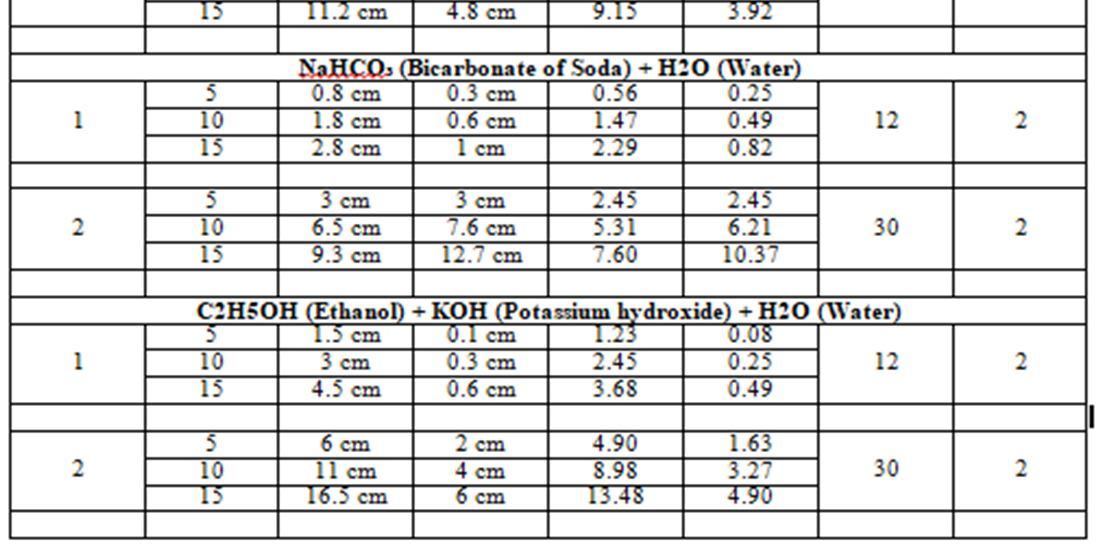
The various solutions tested:
1) NaOH (Sodium hydroxide) + H2O (Water)
2) KOH (Potassium hydroxide) + H2O (Water)
3) NaHCO₃ (Bicarbonate of Soda) + H2O (Water)
4) C2H5OH (Ethanol) + KOH (Potassium hydroxide) + H2O (Water)
TABLE 1: Hydrogen Gas & Oxygen Gas GeneratedAt various voltage and time
ISSN: 2321 9653; IC Value: 45.98; SJ Impact Factor: 7.538
Volume 10 Issue X Oct 2022 Available at www.ijraset.com
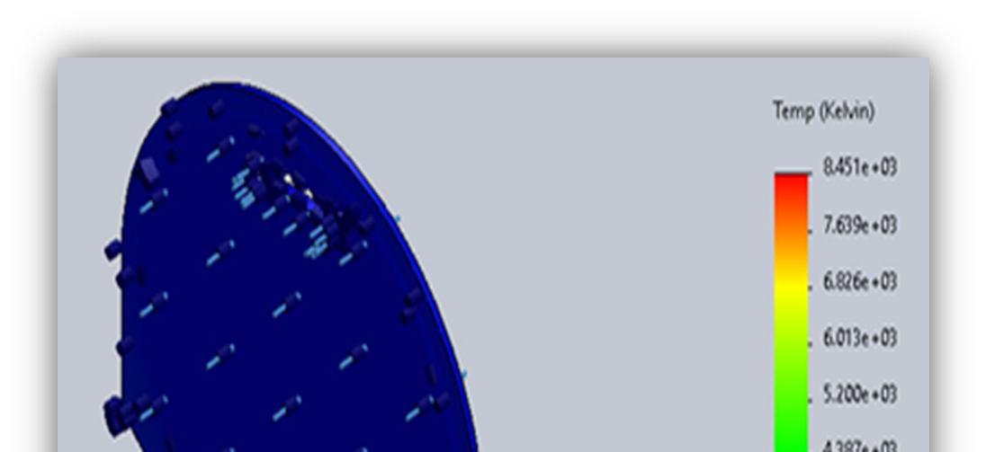
Thermal analysis on Stainless Steel metal plate (Anode & Cathode):
Material = Water column Material = 316L Stainless Steel
Room temp = 30 degree Room temp = 30 degree Max temp = 32.3 degree Max temp = 31.3 degree Min temp = 30.7 degree Min temp = 31.1 degree
TABLE 2: Temperature conditions during testing
Total watts = 2 x 30 = 60 (max condition where current is 2 Amps & 30 volts)
Total current flowing through the circuit = 4 x 60 = 240 watts
Total watts = 2 x 12 = 24 (min condition where current is 2 Amps & 12 volts)
Total current flowing through the circuit = 4 x 24 = 120 watts
Optimum voltage to split water ranges from = 1.23 volts to 1.28 volts. Taking average as = 1.25 volts
Thus, power required to split = 1.25 x 18 = 22.5 Watts Power given = 2*18 = 36 Wasted power = 36 23.4 = 12.6 W In this analysis we applied Heat flux of up to 60 W for extreme condition. Heat transfer coefficient is 250 w/m^2K, which is lower than water. This is to compensate for water loss condition.
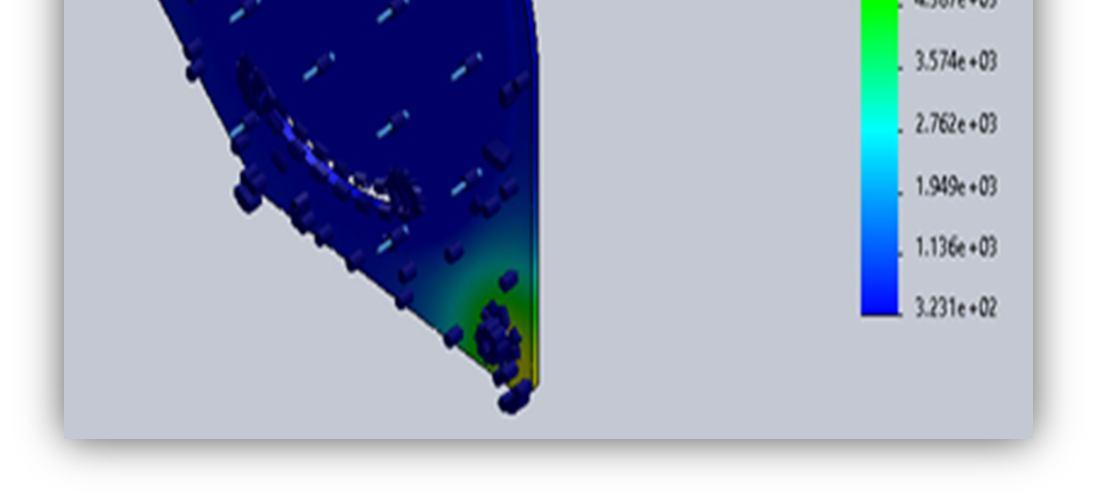
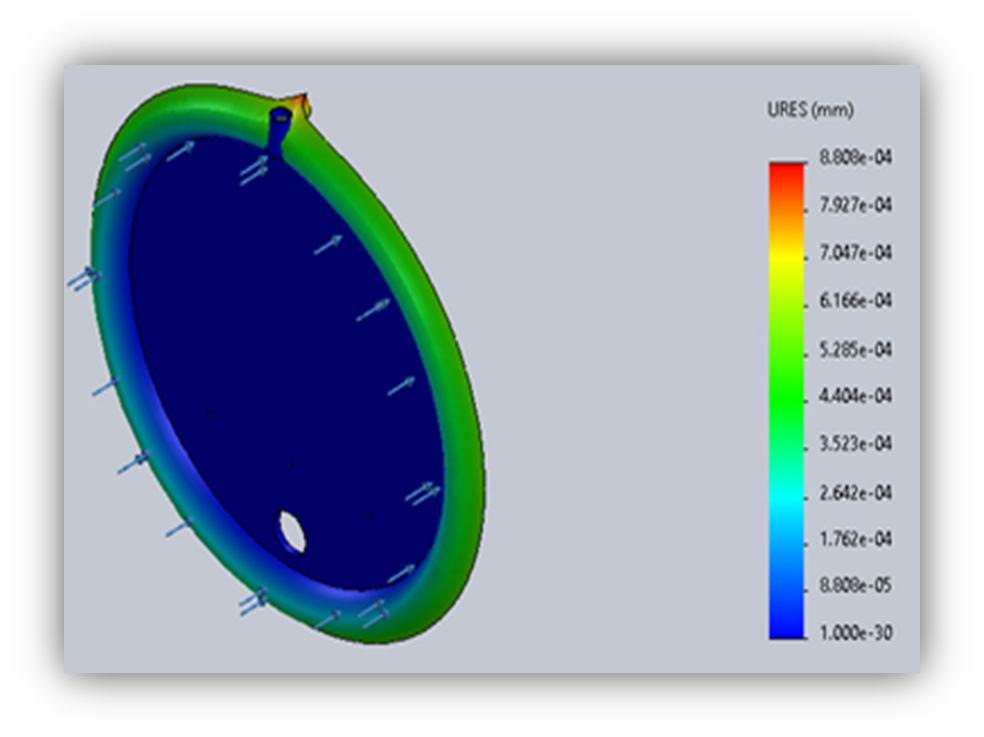
Material for end plate: Acrylic
Material for 3D printed part: Poly carbonate
Force acting: 100N
ISSN: 2321 9653; IC Value: 45.98; SJ Impact Factor: 7.538
Volume 10 Issue X Oct 2022 Available at www.ijraset.com
“For
Yield strength: 4.5x10⁷ N/m2
Tensile strength: 7.3x10⁷ N/m2
Elastic modulus: 3x10⁹ N/m2 Poisson's ratio: 0.35
Mass density: 1,200 kg/m3 Shear modulus: 8.9x10⁸ N/m2”
“For
Tensile strength: 6.27x10⁷ N/m2
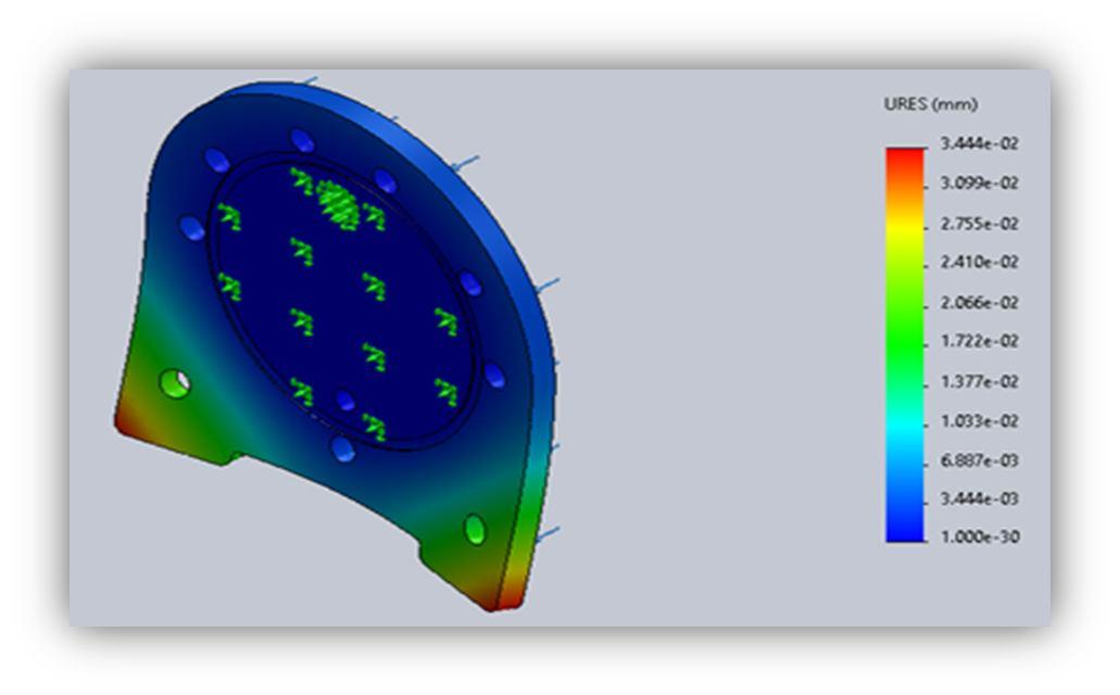
Elastic modulus: 2.32x10⁹ N/m2 Poisson's ratio: 0.3912
Mass density: 1,190 kg/m3 Shear modulus: 8.291x10⁸ N/m2”
Rate of hydrogen and oxygen gas produced. Reactions: “
Reduction at cathode: 2 H+ (aq) + 2e− → H2 (g) Oxidation at anode: 2 H2O (l) → O2 (g) + 4 H+ (aq) + 4e−”
Electrical Charge in Coulombs (C): Q = I X t = 1080 C
ISSN: 2321 9653; IC Value: 45.98; SJ Impact Factor: 7.538
Volume 10 Issue X Oct 2022 Available at www.ijraset.com
A given number is the volume of hydrogen (or any other gas) per mole. Hydrogen per mole has a volume of 2.2414 Liters (22,414 Milliliters) at normal pressure and temperature.
1 mole of Hydrogen yields 2 moles of electrons.
The electrical charge of one mole of electrons (Faraday's Constant) = 1F = 96485 C.
Because we have two moles of electrons, the electrical charge produced by one mole of Hydrogen is equal to two moles of Hydrogen (q)
= 2 X 96,485 C = 192970 C/mole.
Hydrogen Volume per mole = 2.2414 liters, at STP Rate of H2 gas (l/min) = for 1 cell
For complete stack, contains 4 cells
Total Rate of H2 gas (l/min) =0.125 X 4 = 0.54 l/min.
Instead of 2 moles of electrons like we had for Hydrogen, we have 4 moles of electrons for Oxygen, so 4X 96,485 C (q) = 385940 C/mole.
Rate of O2 gas (l/min) = for 1 cell for complete stack, contains 4 cells
Total Rate of O2 gas (l/min) =0.0625 X 4 = 0.25 l/min
Hence total HHO gas produced = 0.54+0.251= 0.79 l/min
1) For NaOH we observed that the process began at 12V, 1 Amp. In the beginning it began to react with the impurities within the stainless steel and the ferric compound in it. But after some time, it began to perform OK.
2) For KOH we found out that initially it reacted with the impurities in the solution and metal but initially later it began to perform in a better way and we observed that it’s much safer to use.
3) For NaCL we observed that it created hydrogen gas but at the anode (positive side) chlorine was getting deposited at the bottom and on mixture of the solution we get ferric chloride. Also, it acts as a poison which can damage the cell.
4) For NaHCO3 we observed at lower voltage and current the solution could perform perfectly but at higher voltage it couldn’t as it breaks down and works in the opposite manner. (i.e.: we get more oxygen and less of hydrogen)
5) For Ethanol, we can get twice the amount of hydrogen gas and less of oxygen gas but this solution can be used only once. After use once we collect the solution it tends to become soapy and also reactive with the adhesive or bonding solution used for holding the components together in the setup. But this can be used only in places where high amount of hydrogen gas is required continuously
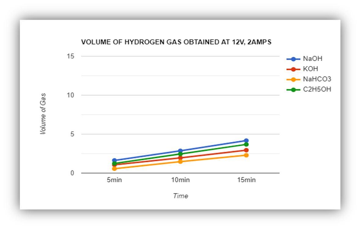
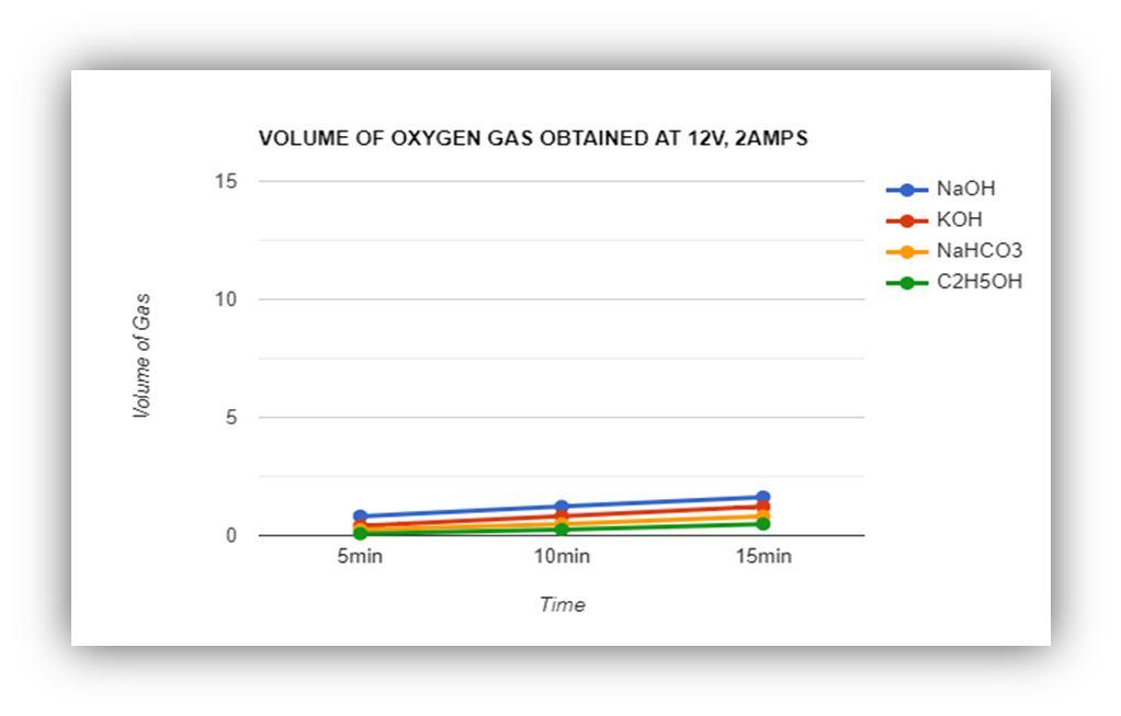
Volume of Hydrogen & oxygen gas obtained at 12V, 2 Amps = 24 Watts
FIGURE 5: Hydrogen Gas Obtained At 12V
ISSN: 2321 9653; IC Value: 45.98; SJ Impact Factor: 7.538 Volume 10 Issue X Oct 2022 Available at www.ijraset.com
Volume of Hydrogen & oxygen gas obtained at 30V, 2 Amps = 60 Watts
12V
FIGURE 7: Hydrogen Gas Obtained At 30V
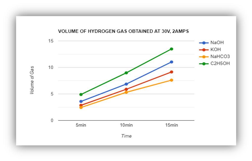
FIGURE 8: Oxygen Gas ObtainedAt 30V
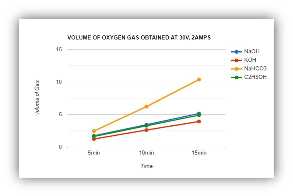
The above graphs show the quantity of hydrogen gas and oxygen which is generated in the cell. The total quantity of the solution (catalyst + water) is 200ml. the recording is done by the meter scale and the calculation is done by the formula of cylinder ( = . By this method we could get an approx. method for calculating the obtained gas in the container. The other method is by accumulating the water which is displaced from the water container by the gas which is generated.
ISSN: 2321 9653; IC Value: 45.98; SJ Impact Factor: 7.538
Volume 10 Issue X Oct 2022 Available at www.ijraset.com
Based on the active surface area of the electrolytic cell, the appropriate current applied was found to be 30watts at max condition and 24 watts at minimum operating condition.
1) When a voltage of 12V is supplied across the stack, the gas production rate is calculated to be 0.95 LPM HHO gas approx. The hydrogen gas produced is 0.75 LPM, while the oxygen gas produced is 0.151 LPM.
2) As the result, the quantity of hydrogen gas produced is twice as much as the quantity of oxygen gas produced. This is due to the large number of mole transfers that occur during the electrolysis process [4] [6]
3) According to the thermal analysis performed using the solid works software no external cooling is required in the design because the maximum temperature rise in the electrode plate and water column is 31.3 C and 32.3 C, respectively. The amount of heat created in the cell is negligible.
4) The active surface area is a critical consideration when designing a cell since it dictates the maximum amount of current that can be applied without the cell overheating. The rate of gas production is then determined by the amount of current
5) The voltage is distributed via the neutral plates in between the electrodes. Anything above 2.2 volts is a waste of energy that leads to overheating and stainless steel corrosion. As a result, neutral plates aid in efficient utilization. The overall total voltage flowing through the fuel cell is 60 watts and 4 cells makes it 240 watts
When it comes to protecting our world, humanity has an uphill struggle. To avoid some of the worst impacts of climate change, we must keep global temperatures from climbing 1.5 degrees Celsius beyond pre industrial levels. To achieve so, global carbon emissions must be zero by 2050. [8] . To attain this aim, a number of solutions will be required, but one technology that is gaining traction is green hydrogen. Green hydrogen is hydrogen that is created only from renewable energy sources. [1].
There are tremendous amount of studies and analysis on
1) Storage of hydrogen gas:
a) Storage in large Tanks
b) Storage in cylinders
c) Storage underground (salt mines, depleted oil wells, underground caves) [9]
2) Use of hydrogen for power or electricity generation
3) Use as fuel of automobiles (combustion or for blends in gasoline and liquid fuels)
4) Used as fuel for gas or diesel power plants
ISSN: 2321 9653; IC Value: 45.98; SJ Impact Factor: 7.538 Volume 10 Issue X Oct 2022 Available at www.ijraset.com
We express our gratitude to the department of mechanical engineering and the department of basic science and humanity for their endless support, guidance and help. We sincerely want to thank Prof. Sandeep Sabnis our project guide who has helped us greatly and guided us in gathering and providing the essential resources, which helped us to put the various ideas together and completing this project in the best possible way. We would like to thank our project coordinator Prof. Cleta Pereira, for the constant support and encouragement received. The mechanical workshop department in helping us fabricates the project, without their guidance and knowledge this wouldn’t be a success.
[1] “Fact Sheet, Fuel Cell & Hydrogen Energy Association”
[2] Kaveh Mazloomi, Nasir b. Sulainam, Hossein Moayedi, “Electrical Efficiency of Electrolytic Hydrogen Production,” Int. J. Electrochemical. Sci., vol. 7 (2012), pp. 3314 3326,April 2012
[3] A. A. Lanjewar, et. al., “Design of HHO Cell Kit”, International Journal of Chemical Sciences and Research (IJCSR), vol (7), PP 1 8, 2017
[4] Emmanuel Zoulias, Elli Varkaraki, Nicolaos Lymberopoulos, Christodoulos N. Christodoulou, George N. Karagiorgis, “AReview on Water Electrolysis,”
[5] “en.wikipedia.org/wiki/Electrolysis_of_water”
[6] “Water Electrolysis & Renewable Energy Systems, Fuel Cell Today”, May 201
[7] Al Jumlat Ahmed, Md. Abdullah Al Munem*, Yasin Imam Arnab, “Developing Prototype and Performance Evaluation of a Hydrogen Generator”, January 2018.
[8] “un.org/sustainabledevelopment/climate change/”
[9] U.Bünger, J.Michalski, F.Crotogino, O.Kruck, “Large scale underground storage of hydrogen for the grid integration of renewable energy and other applications”, 2016
[10] J. Nowotny∗, C.C. Sorrell, L.R. Sheppard, T.Bak. Solar hydrogen: Environmentally safe fuel for the future. Centre for Materials Research in Energy Conversion, School of Materials Science and Engineering, University of New South Wales, Sydney, NSW 2052, Australia
[11] “Rusdianasari Rusdianasari, Yohandri Bow, Tresna Dewi. HHO Gas Generation in Hydrogen Generator using Electrolysis”
[12] “Z. Wang*, R.R. Roberts, G.F. Naterer, K.S. Gabriel. Comparison of thermochemical, electrolytic, photo electrolytic and photochemical solar to hydrogen production technologies. Clean Energy Research Laboratory, Faculty of Engineering and Applied Science, University of Ontario Institute of Technology, and 2000 Simcoe Street North, Oshawa, Ontario L1H 7K4, Canada”
[13] “Pathways to electrochemical solar hydrogen technologies. The Royal Society of Chemistry”
[14] “Hydrogen Basics Solar Production Florida Solar Energy Centre”