
10 IX September 2022 https://doi.org/10.22214/ijraset.2022.46809
Vishal Desai1 , V. M. Bogar2 , Mohammad Zunnoorain3
Applied Mechanics Department, Government College of Engineering, Karad
1M.tech Student, Government College of Engineering, Karad
2 Asst. Professor Applied Mechanics Department, Government College of Engineering, Karad

3M.tech Student, Institute of Engineering and Technology, I.E.T Lucknow
Abstract: The diagrid (diagonal grid) structural design is one of the fascinating structural design ideas for sturdy tall constructions. Diagrid, a new design style for tall, intricate structures, has emerged due to its aesthetic appealand structural effectiveness. Diagrid's façade structural system resists both lateral loads and gravity loads by utilizing a small grid of diagonal components.
As it uses less structural steel than a conventional steel frame, making the structure more environmentally friendly. This study makes use of ETABS to assess tall structures built of Diagrid steel and tall structures using different bracing techniques. Being thin makes high-rise structures extremely vulnerable to lateral forces, thus they must be constructed to provide safety and comfort in accordancewith user needs. In order to combat the lateral stresses that are most common in high rise structures, diagrid and X bracing systems have been created. In this study, the seismic behaviors of diagrid and X braced systems are compared.
The E-tabs software is used to prepare two 36-floor models, one with a diagrid system and the other with an X-bracing system. Story drift, base shear, and member forces are compared while both models are investigated in various earthquake zones. The conclusion reached after looking at all of these variables is that the diagrid system performs better than the X braced system.
Keywords: Diagrid Structural System, High rise buildings, Structural design.
High rise buildings are one of the enormous constructions we encounter in today's globe that would fascinate everyone. The construction of multi story structures is expanding quickly overthe world. Diagonal members are employed in diagrid structural systems to connect the beam and diaphragm, and these members transfer lateral loads and gravity loads. The diagrid methodhas gained enormous popularity in intricate buildings such curving form The use of diagonal elements is fast expanding as a result of the use of diagrid, which replaces traditional vertical columns.
To provide the structure greater optimization, several diagrid system characteristics must be determined, such as the ideal diagonal member angle.

Any high rise building's diagridsystem can be examined for a variety of factors, including the angles at which the diagonal elements are angled, a comparison of moment resisting frame construction to conventional frame construction, and the placement ofthebuilding'sshear wallsat various locationsto study the structure.
Additionally, a significant quantity of structural material is conserved and the project becomes more cost effective by removing everything but the core columns from the design. In fact, the effectiveness of the diagonal members reduces the overall number of internal columns, giving the architect moreroomto createthe objects. Architects and designersmuch prefer this strategy to a braced frame structure. A particular kind of space truss is calleda diagrid. It is constructed up of a perimeter grid made of triangulated truss systems.
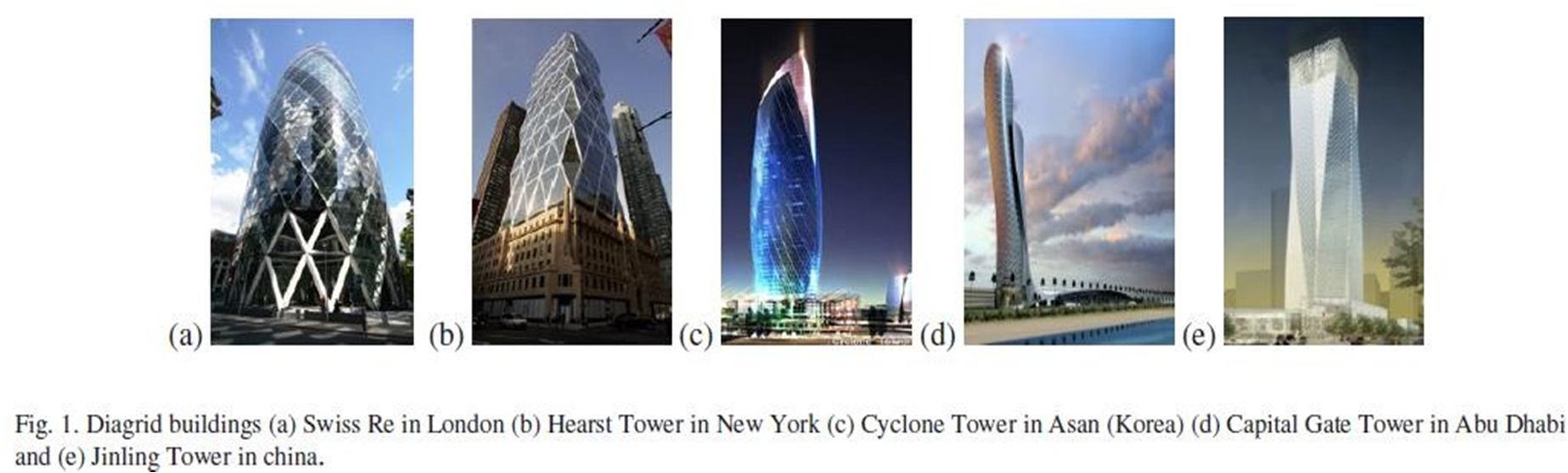
Bycrossing thediagonaland horizontalelements, adiagrid iscreated. TheSwiss Re in London,Hearst Tower in New York, Cyclone Tower in Asan (Korea), Capital Gate Tower in Abu Dhabi, and Jinling Tower in China are some of the well known diagrid structures in the world,as depicted in Fig 1. One example of using a diagrid structural system to sustain a difficult shape is the new Central China Television (CCTV) headquarters in Beijing1
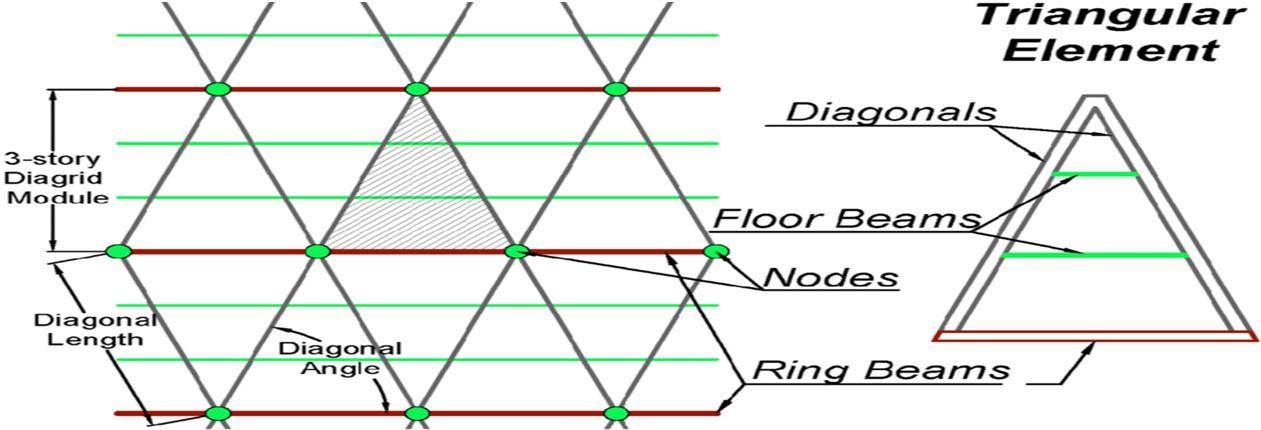
Utilizing sustainable and effective structural techniques and designing freeform trademark structures are two current trends in the construction of tall and unique buildings. Both of thosefashionable characteristics are present in Diagrid, a variant of the tubular constructions[2,3] Diagrids are renowned for their versatility to produce free form structures as well as for beingan aesthetically beautiful and structurally effective system. Both lateral and gravitational loads can be supported by their inclined diagonal members[4 7]. The essential elements of a diagrid frame and its fundamental triangular element are shown in Figure 1. Diagrids have been employed in a variety of iconic and free form high rise structures around the world, including the 595.7 meter Canton Tower, the 51 story Tornado Tower in Doha, Qatar, the 103 storyGuangzhou International Finance Centre in Guangzhou, China, andthe 57 storyThe Bow in Calgary, Canada[8 10] .
By supplying a response modification factor, R, to account for the nonlinear response of the structure during extreme events, design codes like ASCE710 permit elastic analysis forthe design of various structural systems[7]
Steel has become a popular building material and offers avariety of solutions that can make structures morecomfortable, energy efficient, and less expensive to operate.
In recent years, a number of environmentally friendly strategies that reduce the need for structural steel havebeen created. Among these, the diagrid structural system is seen as a potentially effective solution for tall steelstructures. Recently, anew design style for tall, complicated structures has evolved called"diagrid," which is a perimeter structural layout characterised by a small grid of diagonal components involved in both gravityand lateral load resistance.
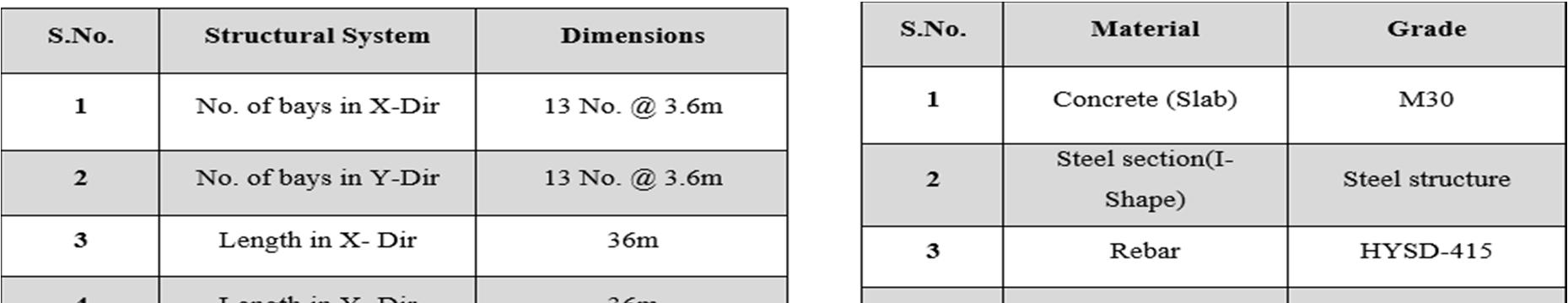
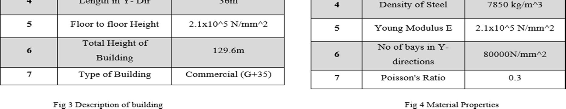
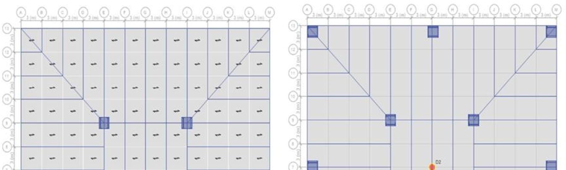
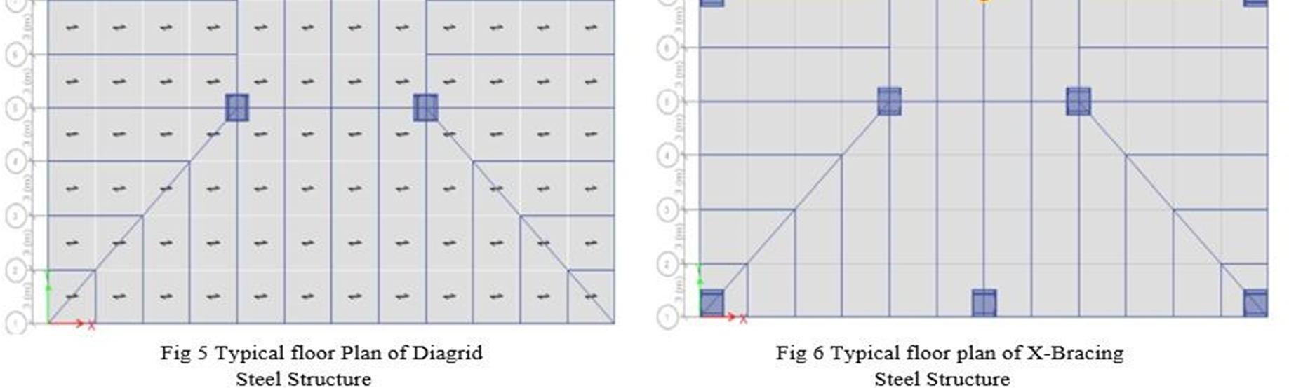
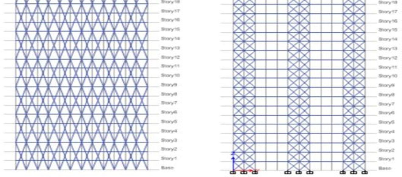
The 36 story structure has a plan dimension of 36 meter x 36 meter. The 3600 mm story height. Fig. 2 depictsthe standard plan and elevation. A pair of braces is situated on the outside of diagrid structures. All along the height, the inclination angle is maintained constant. Along the perimeter, inclined columns are offered at six meter intervals. The diagrid structures' internal frame is only intended to support gravity loads. The floor slab's intended dead load andlive load are 3.75 kN/m2 and 2.5 kN/m2, respectively. According to IS:875 (III) 1987 (Gust factor technique), the dynamic along wind loading is calculated using a base wind speed of 30 m/sec and terrain categoryIII.
ISSN: 2321 9653; IC Value: 45.98; SJ Impact Factor: 7.538


Sep
at www.ijraset.com
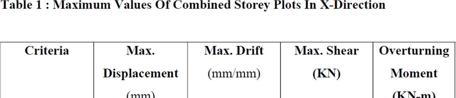
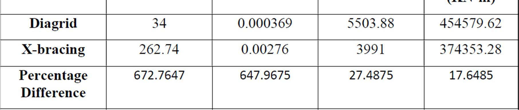
the values of maximum displacement. As can
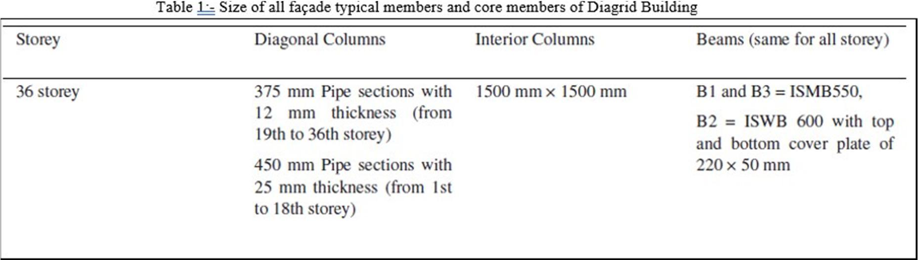
values are lowest when the diagrid is spanning three levels and has an inclination angle of 74.47 Degree. Compared to Steel X Bracing the result are less which shows that Diagrid building saves the consumption of steel in the building and make it sustainable structure. X Bracing uses 50.17 degree of inclination of bracing. Measurements of storey displacement are made in relation to the structure's base. After examining the storey displacement graphs, it was found that the X braced
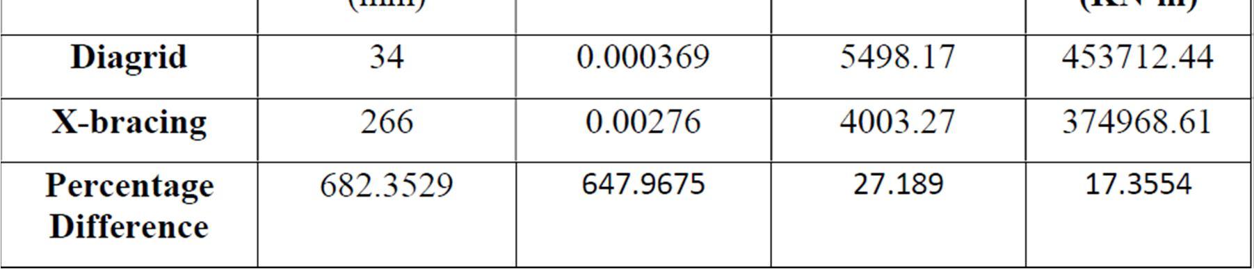
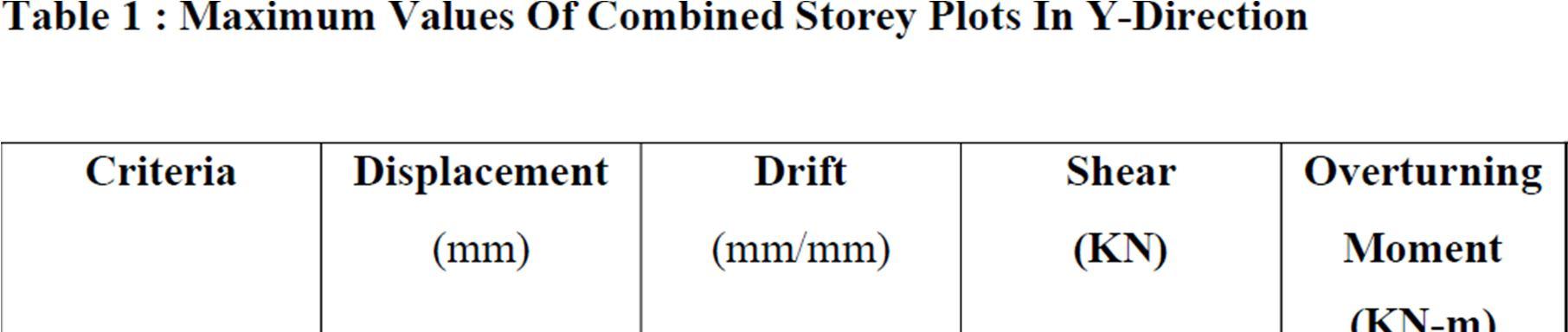
exhibits 682.35 percent greater displacement in the X direction and 672.76 percent more displacementin the Y direction than the diagrid structure. This demonstrates that the structure is firmer withthe diagrid system than with the X braced system.
the
ISSN: 2321 9653; IC Value: 45.98; SJ Impact Factor:


10
Sep
at www.ijraset.com
lowestwhen the diagrid is spanning three
ofbracingat50.17degreethedrift inDiagrid building iscomparativelyless , so building is more stiffer than
Bracing during lateral loading. The findings indicate that, in both the X and Y directions of response, the maximum drift in the X braced structure is 647.96% greater than in the diagrid system. The maximum drift is shown in diagrid structures between the 18th and 22nd floor, and in X braced structures it is seen between the 13th and 18th level. The more rigid foundation of the diagrid construction than the X braced structure is the cause of the difference in maximumdrift
in
It shows that diagrid
ISSN:
Similar to storey shear, the overturning moment is also greatest in diagrid structures a reachesits highest value at diagrid joints. In the X and Y directions, respectively, the overturning moment in the diagrid system is 17.35 and 17.64 percent more than that of the X braced structure.
The pseudo spectralaccelerations for a given time are significantlyhigher in the diagrid systemthan the X bracing system, indicating the diagrid structure's stronger stiffness than the X braced structure.
It is evident fromthe information provided above that the diagrid method gives structures morerigidity than the X bracing system. As a result of its lower stiffness, the X braced structure exhibits more storey displacement and drift, but this is still well below the maximum displacement limit outlined in IS 1893: 2016 Part 1 clause 7.11.1, which states that any building's maximum displacement must not exceed 0.004h, where h is the structure's height. Diagrid structures are more likely to have plastic hinge creation at joints because they experience more shear and overturning forces there. Early plastic hinge creation might cause amechanism of collapse; therefore, joints must be built with greater care and with the appropriatefactor of safety.
ISSN: 2321 9653; IC Value: 45.98; SJ Impact Factor: 7.538
Volume 10 Issue IX Sep 2022 Available at www.ijraset.com
This study presents a detailed analysis and design of a 36 story diagrid steel structure. A standard floor layout measuring 36 m36 m istaken into account.Themodellingandanalysisof structures are done using ETABS software. IS 800:2007 is used to design all structural elements while taking into account all load scenarios. Additionally, diagrid system loaddistribution for 36multi story building. The analysis shows that diagrid columns on theperipheryresist the majorityofthe lateralload, whereas gravityis the main source ofresistance.Both the interior and peripheral diagonal columns support the load. Consequently, internal columns must be planned for merely a vertical load of the structure. The axial force inthe diagonal members on the outside of the structure resists the lateral and gravitational loads,which increases the efficiency of the system. Diagrid structural technology offers greater planning options for the building's interior andoutside spaces. So we can conclude from above analysis as per IS 1893 2016(PART 1) that X Bracingis less efficient and uneconomical as compared to Diagrid Structures. Consumption of steel decreases in Diagrid structure which make it sustainable and eco friendly. And these conceptscan be added to National Green Building Council of India, also.
[1] Leonard J. Investigation of Shear Lag Effect in High rise Buildings with DiagridSystem. M E thesis. 2007;(2004).
[2] Asadi E, Bocchini P. Diagrid: An innovative, sustainable, and efficient structuralsystem. Structural Design of Tall and Special Buildings. 2017;26(8):1 11.
[3] Wang N, Adeli H. Sustainable building design. Journal of Civil Engineering andManagement. 2014;20(1):1 10. doi:10.3846/13923730.2013.871330
[4] E. Mele, M. Toreno, G. Brandonisio, A. De Luca Kim, Struct. DesignTallSpec. Build. 2014, 23, 124.
[5] K. S. Moon, J. J. Connor, J. E. Fernandez, Struct. Design Tall Spec. Build. 2007,16(2), 205.
[6] K. S. Moon, Struct. DesignTall Spec. Build. 2008, 17(5), 895.
[7] 16 of18 ASADI AND ADELI
[8] Y. Niu, C. P. Fritzen, H. Jung, I. Buethe, Y. Q. Ni, Y. W. Wang, Comput. Aided Civ. Inf. Eng. 2015, 30(8), 666.
[9] T. M. Boake, Diagrid Structures: Systems, Connections, Details, Birkhäuser,Switzerland 2014 <http://alltitles.ebrary.com/Doc?id=10838294>
[10] E. Asadi, H. Adeli, Struct. DesignTall Spec. Build. 2017, 26(8).https://doi.org/10.1002/tal.1358
[11] M. Kociecki, H. Adeli, J. Constr. SteelRes. 2013, 90, 283.
[12] ASCE, Minimum Design Loads for Buildings and Other Structures. SEI/ASCE Standard No. 7 10, AmericanSocietyofCivil Engineers, Reston, Virginia2010. FEMA(Federal)
[13] Moon KS, Diagrid Structures for Complex Shaped Tall Buildings, Procedia Engineering,14, (2011), 1343 1350, DOI 10.1016/j.proeng.2011.07.169
[14] Mele E, Toreno M, Brandonisio G, Del Luca A, Diagrid structures for tallbuildings: case studies and design considerations, The Structural Design of Tall and Special Buildings, 23(2), (2014), 124 145, DOI 10.1002/tal.1029.