
10 VII July 2022 https://doi.org/10.22214/ijraset.2022.46047

A shear wall is a structural component provided to the multi storied or tall buildings or ordinary buildings in high wind velocity areas. These walls usually begin from the foundation level, along the length and width of buildings. Their thickness can be above 150 mm or below 400 mm in tall buildings and they are like vertical oriented wide beams that carry the earthquake load towards the Shearfoundation.wallis a concrete wall made to resist lateral forces acting on tall buildings. Shear walls are vertical elements of the horizontal force resisting system. When shear walls are designed and constructed properly, they will have the strength and stiffness to resist the horizontal forces. Properly designed and detailed buildings with shear walls have exhibited very good performance during the past earthquakes. Just like reinforced concrete (RC) beams and columns, RC shear walls also perform much better if designed to be ductile. Overall geometric proportions of the wall, types and amount of reinforcement, and connection with the other elements in the building help in improving the ductility of walls. In building construction, a rigid vertical diaphragm capable of transferring lateral forces from exterior walls, floors, and roofs to the ground foundation in a direction parallel to their planes. Examples are the reinforced concrete wall or vertical truss. Lateral forces caused by wind, earthquake, and uneven settlement loads, in addition to the weight of structure and occupants, create powerful twisting (torsional) forces. These forces can literally tear (shear) a building apart. Reinforcing a frame by attaching or placing a rigid wall inside it maintains the shape of the frame and prevents rotation at the joints. Shear walls are especially important in high rise buildings subject to lateral wind and seismic forces. Need of the Shear Wall: While columns and load bearing walls keep buildings standing up, carrying the compression load of the structure down to its foundation, the shear wall is what keeps structures from blowing over, resisting the lateral forces of wind and seismic activity. Almost all houses have external shear walls, but internal shear walls are typically found only in larger houses and high rise buildings subject to lateral winds and seismic forces. The tall the building, the greater the need for internal shear walls and a lateral force resisting system. Most homes and buildings in high wind and earthquake prone regions require exterior shear walls. However, larger houses and high rise structures also need interior shear walls to protect against lateral wind and seismic forces.
II. OBJECTIVES
1) To model and analyze G+10 frame structure having different location of shear wall in the structure using ETABS software.
Seismic Behaviour and Design of RC Shear Wall using ETABS software
Abstract: The present paper shows seismic behavior of building under the action of earthquake load [ bhuj earthquake] by performing time history analysis. Nowadays buildings with shear walls are more popular than buildings without shear wall in earthquake prone areas due to its resistance during earthquake. In this project G+10 RCC building is considered for the structural analysis for zone III and suitable load combination. The purpose of this study is to find the prime location of shear wall and then investigate the effectiveness of best shear wall for the RCC structure. The structure is analyzed for earthquake in the type of structural system using ETABS software. Wall which is mainly designed to resist lateral forces in its own plane is called shear wall Shear wall are mainly flexural membrane which are specially designed to resist lateral forces which are caused by seismic forces and other forces. Shear wall starts from foundation level and should be continuous throughout of the building.
Mr.Prasad J.Jadhav1 , Mr.Vikramsinh S. Tiware2, Mr. Vivek V. Mane3 , Mr.Nitish A.Mohite 4 , Mr. Siddhesh Tiwale S5 1, 2, 3, 4Assistant Professor, 5B.Tech. Student,Department of Civil Engineering, BVCOE, Kolhapur
Keywords: RCC building, ETABS, Time History Analysis, Shear wall, Seismic analysis I. INTRODUCTION
3) To find lateral displacement in x and y direction
4) To study the displacement of the building.
International Journal for Research in Applied Science & Engineering Technology (IJRASET) ISSN: 2321 9653; IC Value: 45.98; SJ Impact Factor: 7.538 Volume 10 Issue VII July 2022 Available at www.ijraset.com 4679©IJRASET: All Rights are Reserved | SJ Impact Factor 7.538 | ISRA Journal Impact Factor 7.894 |
2) Comparative study of seismic behaviour of building with shear wall and without shear wall by performing nonlinear time history analysis.


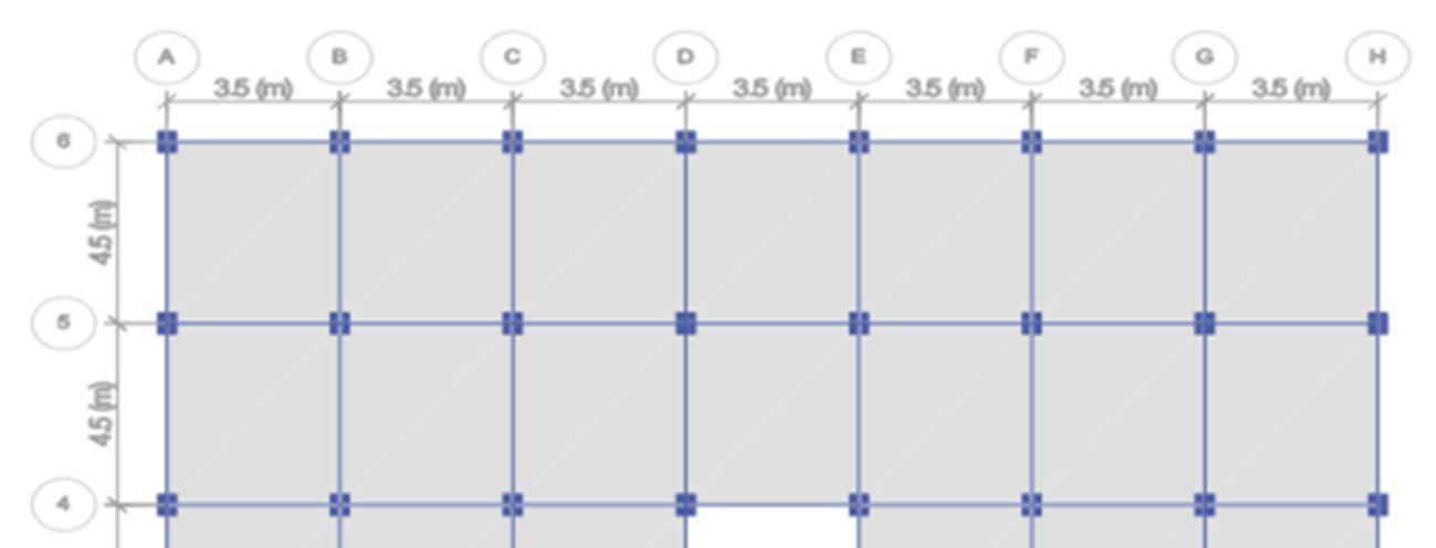
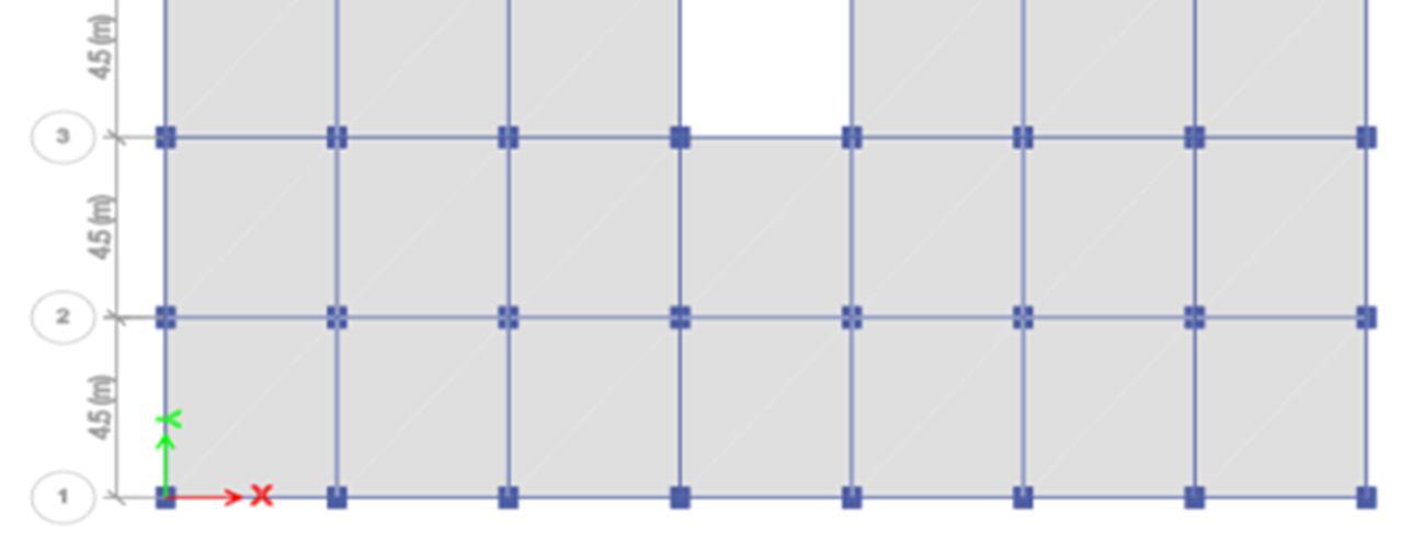
International Journal for Research in Applied Science & Engineering Technology (IJRASET) ISSN: 2321 9653; IC Value: 45.98; SJ Impact Factor: 7.538 Volume 10 Issue VII July 2022 Available at www.ijraset.com 4680©IJRASET: All Rights are Reserved | SJ Impact Factor 7.538 | ISRA Journal Impact Factor 7.894 | III. METHODOLOGY A. Problem Statement 1) Structure: Frame R.C.Shear wall 2) No. of storey : G +10 3) Type of building : Public building 4) Foundation and soil Type : Isolated footing and medium soil. 5) Unit weight of concrete : 25 kN/m3 6) Column 400×550mm [ up to 4th floor] 7) Column 300×450mm [above 4th floor] 8) Beam 230×450mm 9) Slab 150mm 10) Shear wall 230mm 11) Concrete M35 Grade, HYSD Fe500 12) Storey height a) Ground storey 3.50 m b) Upper storey 3.20 m 13) Modal damping = 0.05 I. 14) Roof slab : Floor finish 1.5 KN/m2. 15) Slab : Floor finish 1.5 KN/m2. Live load 3 KN/m2. 16) Roof beam : Parapet wall load 5.52 KN/m. 17) Beams : Masonry wall load 13.8 KN/m. FIG 1. Plan Dimensions StatemenFinalizingmodelandProblemt Study softwareETABSof PreparationofvariousModelinsoftware ApplyingLoadstostructure Analysisofmodelforvariouspositionsofshearwall Comparativestudyofseismicbehaviourofbuilding Result Conclusionand
provided
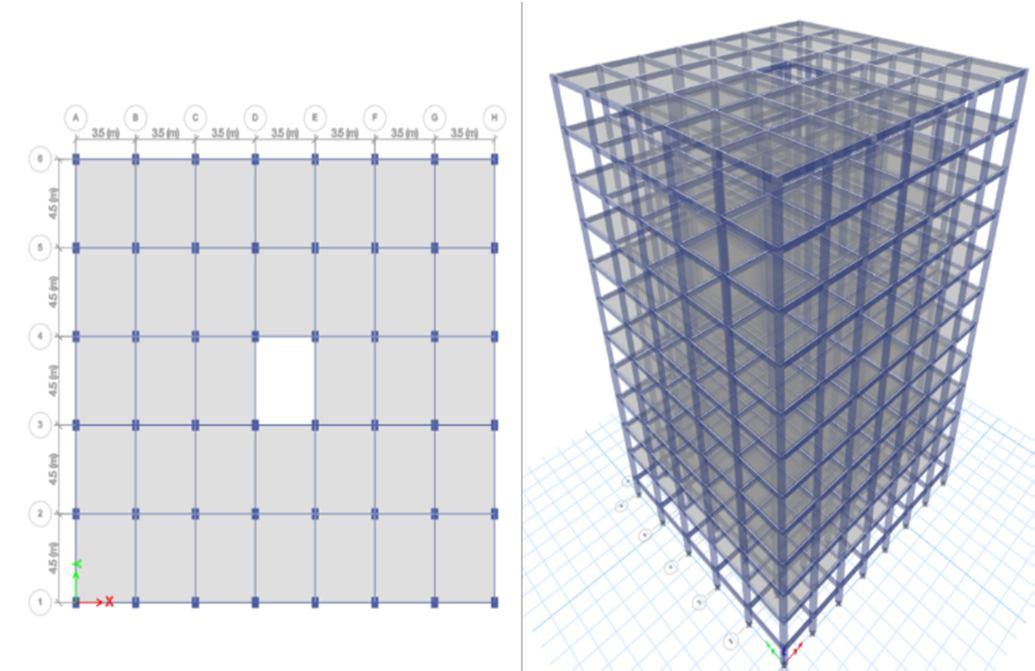
FIG Model 1) G+10 when no shear wall FIG 3. Model 2) G+10 When shear wall at core
Accelerogram
provided
Table 2: Load intensities Masonry wall load 13.8 KN/m. Parapet wall load 5.52 KN/m. Floor finish load 1.5 KN/m2 Live load 3 KN/m2 B. Preparation Of Various Model In Software
of the building
is provided
International Journal for Research in Applied Science & Engineering Technology (IJRASET)
The main aim of this paper is to find effective location of shear wall either inner or outer periphery of the building in G+10 RC building Structure. And also, comparative study on Seismic behaviour of building with shear wall and without shear wall. The following analysis are carried out as per IS: 1893 2016(Part I) for G+10 storied building models. For this analysis, Seismic zone III is considered. According to IS: 1893 2016 (Part I) Zone Factor, Z=0.16, Importance factor, I=1.5, Response reduction factor, R=5.00,are applied during analysis. Performance is analysis by performing Dynamic Nonlinear Time history analysis
ISSN: 2321 9653; IC Value: 45.98; SJ Impact Factor: 7.538 Volume 10 Issue VII July 2022 Available at www.ijraset.com 4681©IJRASET: All Rights are Reserved | SJ Impact Factor 7.538 | ISRA Journal Impact Factor 7.894 |
filtered between 0.07 Hz and 27.0 Hz Initial Velocity = .1411E 02 m/s Initial Displacement = 3.970 mm Peak Acceleration = 1.0382 m/s/s at 46.940 sec Acceleration data points (in m/s/s) at .005 sec. In this analysis, we have prepared 6 similar models with different location of shear wall and one is without shear wall to find effective parameters like lateral displacement of
Method The analysis is carried out using ETABS software. To find parameters like lateral displacement in x and y direction. Time history analysis performed in all the models for Bhuj earthquake of January 26, 2001 at 08:46:42.9 I.S.T. Mag: 7.0 mb, 7.6 Station:MS Ahmedabad Lat & Long 23 02 N, 72 38 E Comp: N 78 E
2.
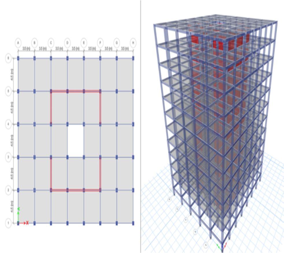
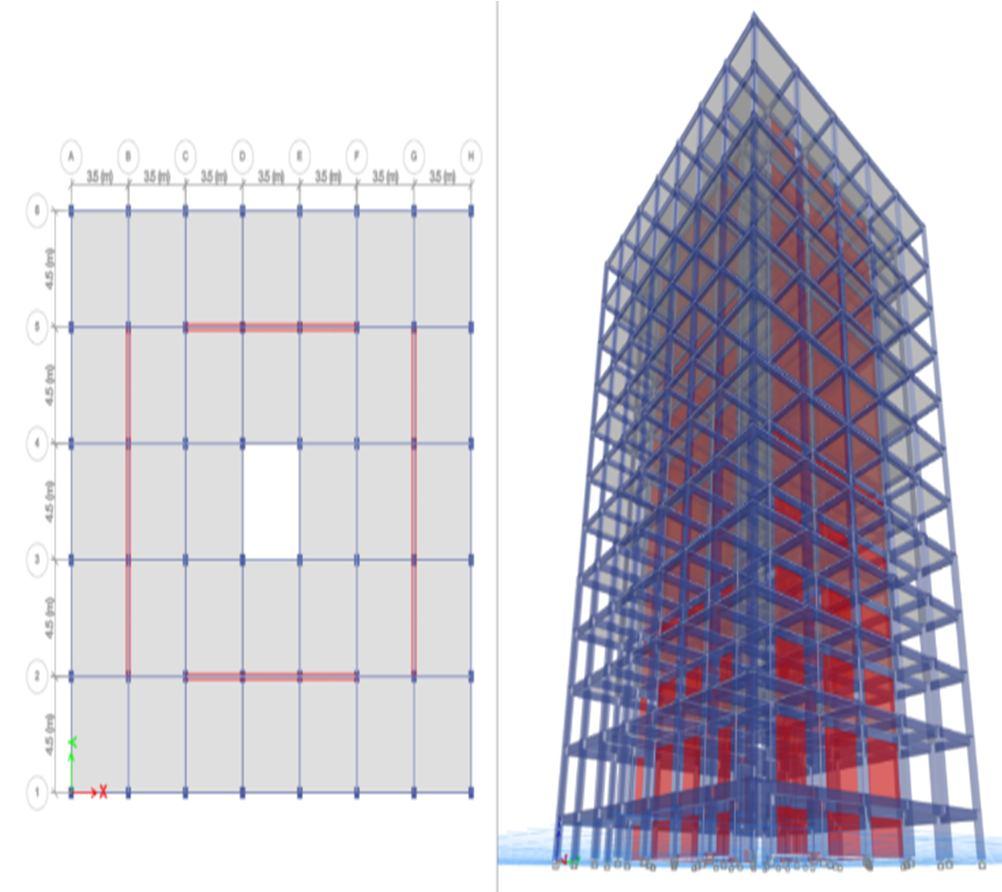
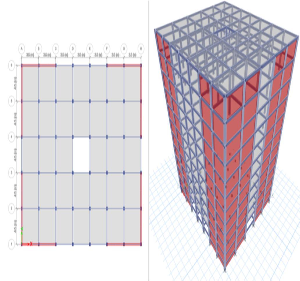
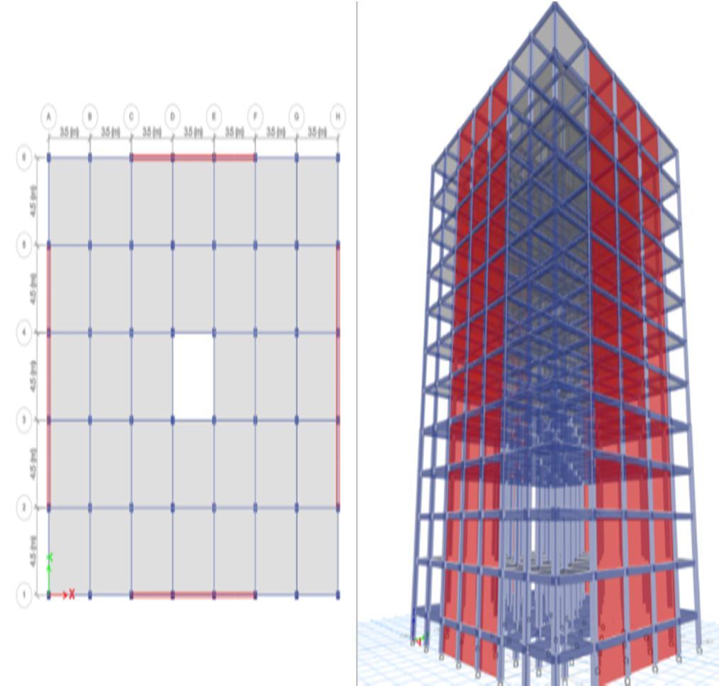
Bandpass Tablebuilding.1:Different location of shear wall Model 1 G+10 when no shear wall Model 2 G+10 When shear wall provided at core of the building. Model 3 G+10 Channel section of shear wall at inner periphery of building. Model 4 G+10 When shear wall provided at inside of building. Model 5 G+10 when shear wall provided at corner of the building. Model 6 G+10 When shear wall at outer periphery of the building.
is provided.
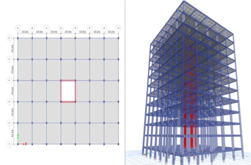
International Journal for Research in Applied Science & Engineering Technology (IJRASET) ISSN: 2321 9653; IC Value: 45.98; SJ Impact Factor: 7.538 Volume 10 Issue VII July 2022 Available at www.ijraset.com 4682©IJRASET: All Rights are Reserved | SJ Impact Factor 7.538 | ISRA Journal Impact Factor 7.894 | FIG 4. Model 3) G+10 Channel section of shear wall at inner periphery of building. FIG 5. Model 4) G+10 When shear wall provided at inside of building FIG 6. Model 5) G+10 when shear wall provided at corner of the building FIG 7. Model 6) G+10 When shear wall provided at outer periphery of the building IV. RESULTS AND DISCUSSION The results obtained from time history analysis performed in all the models for Bhuj earthquake of January 26, 2001 at 08:46:42.9 I.S.T. Mag: 7.0 mb, 7.6 MS 1) Station: Ahmedabad 2) Lat & Long 23 02 N, 72 38 E Comp: N 78 E 3) Accelerogram Bandpass filtered between 0.07 Hz and 27.0 Hz 4) Initial Velocity = .1411E 02 m/s 5) Initial Displacement = 3.970 mm 6) Peak Acceleration = 1.0382 m/s/s at 46.940 sec 7) Acceleration data points (in m/s/s) at .005 sec.
8) By performing time history analysis by considering Bhuj earthquake, it has been found that model 3 shows lesser displacement in x direction as compared to the other models.
5) Model 2 gives less performance as compared to other models.
3) The maximum story drift in most of the cases produced found at the seventh floor.
9) By performing time history analysis by considering Bhuj earthquake, it has been found that model 5 shows lesser displacement in y direction as compared to the other models.
4) In all building models (time history analysis), it has been found that large c/s area of shear walls with respect to that total length of structure shows lesser displacement as compared to the other models.
7) Providing shear walls at building coincides with CG locations substantially reduces the displacements in earthquakes.
6) The seismic analysis of reinforced concrete frame regular structure is done by both linear static and nonlinear time history analysis to determine the optimum positioning of the shear wall.
1) Based on time history analysis, it can be observed that the building with shear wall showed better performance in term of reduction of displacement, the reduction of displacement in the shear wall model was 52% as compared to the building without shear wall.
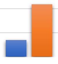
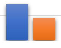
X-DRECTION 172 86 14 26 23 29 Y-DIRECTION 152 69 44 17 13 18 172 86 14 26 23 29 152 69 44 17 13 18200180160140120100806040200 MAX. LATERAL DISPLACEMENT IN MM X-DRECTION Y-DIRECTION
shearsectionChannel3.G+10ofwallatinnerperipheryofbuilding. 4.G+10 when shear insideprovidedwallatofthebuilding. 5.G+10 when shear cornerprovidedwallatofthebuildng 6.G+10 when shear outerprovidedwallatperiferryofbuilding.
From above results the building 5 shows lesser displacement in both x and y direction
International Journal for Research in Applied Science & Engineering Technology (IJRASET) ISSN: 2321 9653; IC Value: 45.98; SJ Impact Factor: 7.538 Volume 10 Issue VII July 2022 Available at www.ijraset.com 4683©IJRASET: All Rights are Reserved | SJ Impact Factor 7.538 | ISRA Journal Impact Factor 7.894 | Graph 1. MAX. LATERAL DISPLACEMENT IN MM
V. CONCLUSION
10) The presence of shear wall can affect the seismic behaviour of frame structure to a large extent, and the shear wall increases the strength and stiffness of the structure.
11) It has been found that the model 5, when shear wall provided at corner of the building is the better location of shear wall 1.G+10 when no shear wall is provided. 2.G+10 when shear providedwallatcoreofthebuilding
2) Results shows that displacement both in X & Y direction considerably reduced by using shear walls.


[13] Satish S. Kotwal, Vidyanand S. Kadam, Mayur M.More, Ananda S Patil, Nitish A Mohite ,” A Literature Review on Beam Column Joints with Different Loading Condition and Methods of Strengthening”, International Journal for Research in Applied Science & Engineering Technology, Volume 10 Issue V, pp.4017 4022, May 2022.
[7] Hidalgo.P.A. (2002). “An analytical model to predict the inelastic seismic behavior of shear wall, reinforced concrete structures”, Engineering Structures 24, 85 98Younis Ahmad Malik Ravinder Singh, Dr. Pooja Sharma, in Department of Civil Engineering, Desh Bhagat University, Mandi Gobindgarh, Punjab. in IJIRS “Road Accidents & Safety Challenges”(2018).
[16] Nitish A. Mohite, Mayur M. More, An Evaluation of Road Safety Performance for Selected Road Stretches in Kolhapur City, ”, International Journal for Research in Applied Science & Engineering Technology, Volume 10 Issue VII, pp.1549 1554, July 2022.
ISSN: 2321 9653; IC Value: 45.98; SJ Impact Factor: 7.538 Volume 10 Issue VII July 2022 Available at www.ijraset.com All Rights are Reserved | SJ Impact Factor 7.538 | ISRA Journal Impact Factor 7.894 | REFERENCES
[3] Pankaj Agarwal and Manish Shrikhande “Earthquake Resistant Design of Structures” PHI Learning Private Limited, New Delhi.
[11] Mayur M. More ,Nitish A. Mohite, ,” A Literature Review on Beam Column Joints with Different Loading Condition and Methods of Strengthening”, International Journal for Research in Applied Science & Engineering Technology, Volume 10 Issue V, pp.4017 4022, May 2022. 12..
[5] Dr. B. Kameshwari, Dr. G. Elangovan, P. Sivabala, G.Vaisakh (2011). “Dynamic Response of High Rise Structures Under the Influence of Discrete Staggered Shear Walls.” International Journal of Engineering Science and Technology, ISSN: 0975 5462 Vol. 3 No.10 October 2011.
[12] .Nitish A. Mohite, Vinayak B. Patil,” Response Spectrum Analysis of G+ 15 Story Building with and without Base Isolation System”, International Journal for Research in Applied Science & Engineering Technology, Volume 9 Issue V,pp.1265 1269, May 2021.
[14] A Review Paper on Base Isolators Subjected to Near Field (NF), Far Field (FF) And Low Frequency Earthquakes, Mayur M.More , Vidyanand S. Kadam , Girish M. Malu , International Journal for research in applied science and engineering technology , Volume 9, Issue V,2021.
[10] Nitish A. Mohite, Vinayak B. Patil,” Response Spectrum Analysis of G+ 15 Story Building with and without Base Isolation System”, International Journal for Research in Applied Science & Engineering Technology, Volume 9 Issue V,pp.1265 1269, May 2021.
[2] IS: 13920 1993, Indian Standard code of practice for ductile detailing of concrete structures subjected to seismic forces, Bureau of Indian Standards, New Delhi, 1993.
[1] IS : 1893 1984, Indian Standard criteria for earthquake resistant design of structures, Part 1 General provisions and buildings, Bureau of Indian Standards, New Delhi, 1984.
[6] Ashraf. M. (2008). “Configuration of a multistorey building subjected to lateral forces”, Asian Journal of Civil Engineering (Building and housing) Vol 9, No 5, 525 537.
[8] Nitish A. Mohite, Mayur M. More,” Comparative seismic analysis study of G+ 20 story building with flat slab and conventional slab using ETABS”, International Journal for Research in Applied Science & Engineering Technology, Volume 9, Issue XI, pp.32 38,November 2021.Mr. Nitish A. Mohite, Mr. P.K.Joshi, Dr. W. N. Deulkar:” Comparative Analysis of RCC and Steel Concrete Composite (B+G+ 11 Storey) Building”, IJSRP Volume 5, Issue 10, October 2015 edition.
[9] Nitish A. Mohite, Vinayak B. Patil,” Structural Analysis of Steel Transmission Tower for different Risk Coefficients A Case Study”, International Journal for Research in Applied Science & Engineering Technology, Volume 7 Issue VII, pp.1295 1300, July 2019.
[15] Effect of Zone Factor on Seismic Parameters of RC Building , Satish S. Kotwal , Vidyanand S. Kadam , Mayur M. More ,International Journal for research and development in technology , International Journal of Advance Research in Science and Engineering , Volume 12,Issue 1, 2019
[4] Seismic Behavior of Buildings with Shear Wall Mahendra Kumar Assistant Professor At Vivekananda Global University Jaipur Civil Engg Department Seismic Behavior of RCC Shear Wall Under Different Soil Conditions Anand, N. Assistant Professor Anshuman. S, Dipendu Bhunia ,BhavinRamjiyani (2011), “Solution of Shear Wall Location in Multi Storey Building.” International journal of civil and structural engineering Volume 2, no 2, 2011.
International Journal for Research in Applied Science & Engineering Technology (IJRASET)
4684©IJRASET: