
10 XI November 2022 https://doi.org/10.22214/ijraset.2022.47405
ISSN: 2321 9653; IC Value: 45.98; SJ Impact Factor: 7.538 Volume 10 Issue XI Nov 2022 Available at www.ijraset.com


ISSN: 2321 9653; IC Value: 45.98; SJ Impact Factor: 7.538 Volume 10 Issue XI Nov 2022 Available at www.ijraset.com
Kumar Gandharv1,
Dolendra Patel2
1PG
Scholar,2
Assistant Professor, Department of Civil Engineering, Shri Shankaracharya Technical Campus SSGI, BhilaiAbstract: The addition of shear wall is a type of global retrofitting. The shear wall offers great resist to lateral loads. The response spectrum is used in this study. It improves the structural performance of building subjected to lateral forces due to earthquake excitation. The paper deals with the investigation of building frame with L-shape shear wall placed at different location such as center and diagonally. The result show that center location is performing better as compared to other cases. The reference model shows maximum displacement.
Keywords: Shear wall, Center, Diagonally, Displacement
A shear wall is a structural component used in multistory or tall buildings, as well as ordinary buildings, in high wind areas. These walls typically begin at the foundation level and run the length and width of the building. In tall buildings, their thickness can be above 150 mm or below 400 mm, and they act as vertically oriented wide beams that carry the earthquake load towards the foundation. Reinforced concrete walls and reinforced concrete slabs make up an RC wall. Their wall thicknesses range from 140 mm to 500 mm, depending on the age of the building and the amount of thermal insulation required. Typically, these walls remain at the entire building's height; however, some walls are closed to the road front or basement level to allow for industrial or parking areas. Plywood is the most common material used in the construction of shear walls. Because of the advancement of prefabricated shear panels, these walls now reinforce small shear assemblies that fall on both sides of the opening.
The selection of seismic analysis method type to analyze the structure depend upon the external action, the behavior of structural material and type of structural modal selected. In bureau of Indian Standards, these four methods of analysis are defined i.e., Linear Static Analysis, Linear Dynamic Analysis, Non Linear static analysis & non Linear dynamic analysis.
Fig. 1 Techniques of Seismic

ISSN: 2321 9653; IC Value: 45.98; SJ Impact Factor: 7.538 Volume 10 Issue XI Nov 2022 Available at www.ijraset.com
The following are the literature study for RCC building having shear walls & bracing
1) Naresh and Mood (2019) [14] investigated the seismic performance of a multi story R.C. framed structure with a shear wall. The seismic performance of R.C. framed buildings of 6, 12, 24, and 36 stories was evaluated using the ETAB program's elastic and inelastic analyses. Eight models with a plan area of 30 m X 20 m and a height of 3 m were created for each type of storey
2) Ashok Kankuntla (2016) [19] used finite element modelling to investigate the behaviour of a shear wall with an opening under seismic load action on member forces. As a result, the current study compares the seismic performance of a 15 story building with openings in the shear wall in earthquake zone V. For seismic analysis, the seismic coefficient method and the response spectrum method are used. The SAP software is used, and the outcomes are compared. The position of the shear wall is determined for all building models by changing the sizes and shapes of the openings in the shear wall.
3) Maikesh Chouhan (2016) [20] put his classroom knowledge to use by designing a multi story residential building. In multi story buildings, shear walls are more effective at resisting lateral loads. Steel and reinforced concrete shear walls are kept in major positions of multi story buildings that are designed to withstand seismic and wind forces. Shear walls are very powerful structural elements that, when used properly, can significantly reduce deflections and stresses.
The research work on the varying location of L shear wall in building frame using ETABS software. Response spectrum analysis is used in this study. The loads measured are taken in accordance with the IS 875 (Part1 & Part2), IS 1893:2002/2016. In this study, the effect of shear wall in the building under seismic loading is been analyzed carried by Seismic Zone V using ETABS software
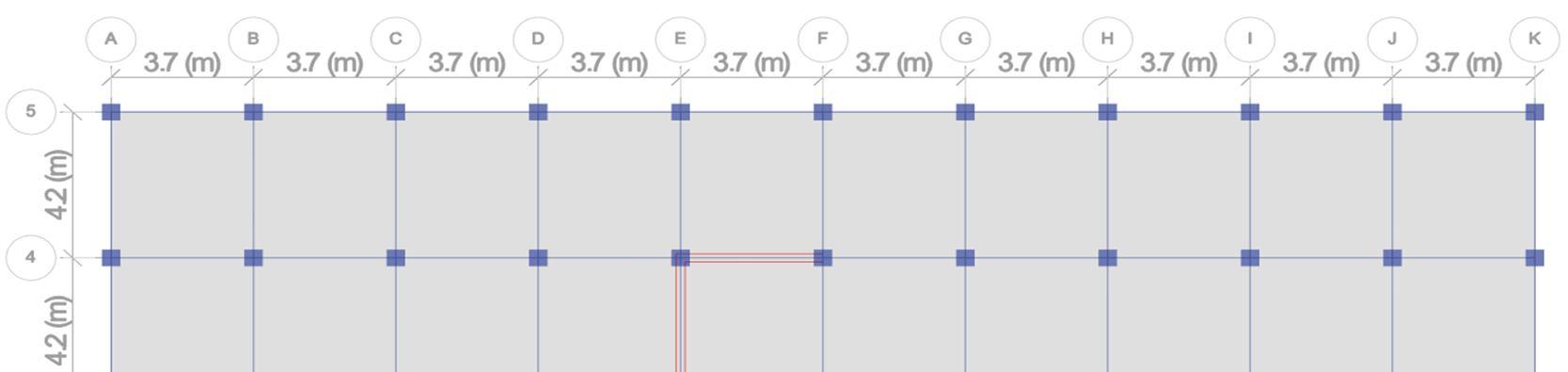
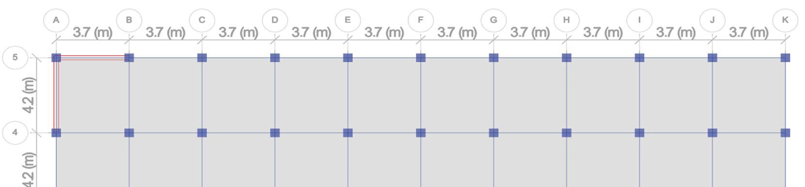
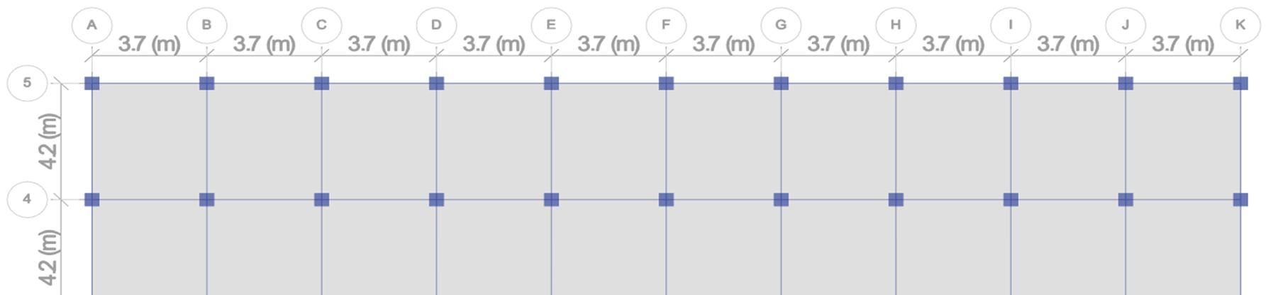
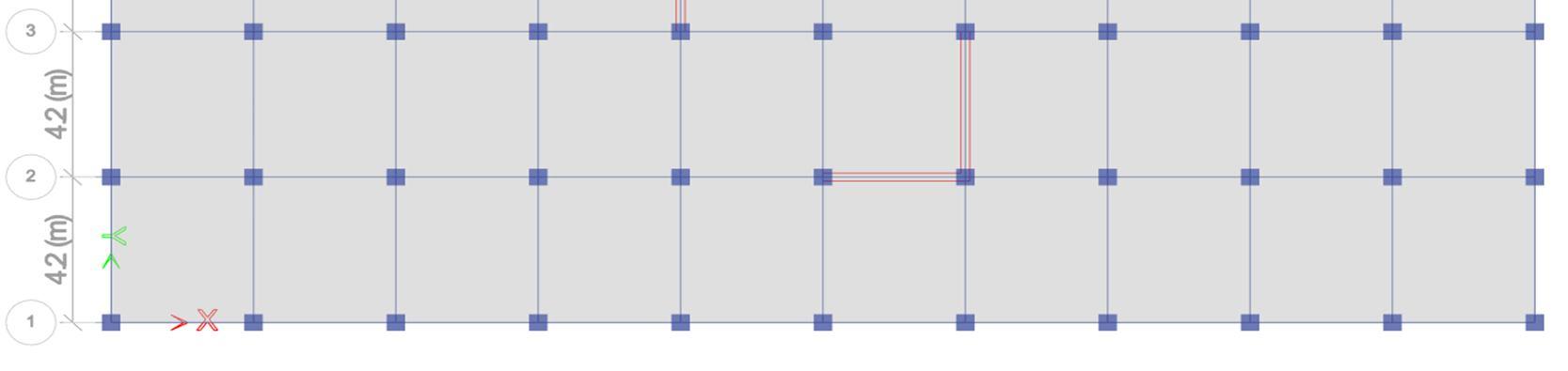
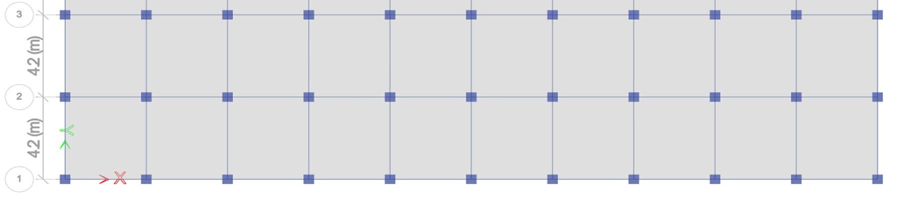
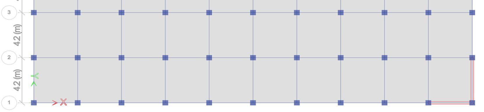
The built up area of asymmetry building considered here are taken equal for all different cases. The building is of size i.e., 3700 mm X 1680 mm with a height of (G+10) Storey. The floor to floor height is taken as 4000 mm for all the structures and also the section properties is also common for all case frame structures. The following below is the Case Study to be analyzed and designed in this thesis
Table 1 Research Work on Cases
Description of Case Study Notations Reference Model RM
Model having shear wall placed at the center BW1 Model having shear wall placed diagonally BW2
The data of structure utilized in the work in the form of tabulation considered for design and analysis of frame are given below
Table 2 Structural Properties
Total Built Up Area 3000 X 1680 mm
Number of Stories G+10
Floor to floor Height 4.0 meter
Size of Columns 450X 450 mm
Beam Size 230 X 450 mm
Slab/Plate thickness 150 mm
Shear Wall thickness 230 mm
Dead load IS 875 Part 1
Live load IS 875 Part 2
Roof live load IS 875 Part 2
Earthquake load IS 1893:2016
ISSN: 2321 9653; IC Value: 45.98; SJ Impact Factor: 7.538 Volume 10 Issue XI Nov 2022 Available at www.ijraset.com
ISSN: 2321 9653; IC Value: 45.98; SJ Impact Factor: 7.538 Volume 10 Issue XI Nov 2022 Available at www.ijraset.com
These building frames models are made up of two basic materials i.e., concrete, and reinforced steel. The table given below shows the properties of materials considered for design and analysis of all RCC frame buildings.
Table 3 Material Properties used in all Frames
Particular Details Grade of Concrete M30 Grade of Main Steel Fe500 Grade of Secondary Steel Fe500 Beam & column cover 25 mm & 40 mm Density of Reinforced Concrete 25 KN/m3 Young’s modulus of steel 2 X 10 5 N/mm2
The loads which are to be studied in the project is discussed under following clauses below in which their calculation detail is also been discussed such as Primary load, Seismic Load & their load combination etc.
In this analysis, dead load includes dead load of the slab, dead load of beam & column, dead load of external walls and dead of internal walls. DEAD LOAD is designated as D.L in ETABS.
# Self Weight of Slab/Plate = (unit weight of concrete X thickness of slab) = 25 X 0.15 = 3.75 KN/m2
# Self Weight of Column (0.45x0.45) = = (unit weight of concrete X size of column) = (25 X 0.45X 0.45) = 5.0625 KN/m (per meter height)
# Self Weight of Beam in all floors = = (unit weight of concrete X depth of beam X width of beam) = 25 X 0.45 X 0.23 = 2.5875 KN/m
In this research, live load includes live load for all the floors as it is considered from the commercial building category given in IS 875 Part 1 and live load for roof is also considered from same above code. LIVE LOAD is designated as L.L. and ROOF LIVE LOAD is designated as R.L.L in ETABS. Here we consider
Live load for all the floors = 5 KN/m2
Live load for roof (at Terrace) = 1.5 KN/m2
Earthquake load or seismic load calculation involves the full dead load plus the percentage of live or imposed load as per IS 1893:2016 considerations and importantly for calculating earthquake or seismic load. Also, as per IS 1893 Seismic weight of each floor is its full dead load plus approximate amount of live or imposed load. In this study, the approximate amount of live or imposed load considered is 50% of the total live load as per IS 1893 (Table 8) and all the rest calculation is done with the help of ETABS Software. SEISMIC OR EARTHQUAKE LOAD is designated as DQX & DQY where “DQ” stands for Dynamic Earthquake load whereas X & Y represents their respective lateral direction.
ISSN: 2321 9653; IC Value: 45.98; SJ Impact Factor: 7.538 Volume 10 Issue XI Nov 2022 Available at www.ijraset.com
The reports for the analysis is been exported from the modelling, and further collected and compared with all the cases shown below
35
30
25
20
15
10
5
0
Displacement along X-Direction (mm)
Storey 11Storey 10 Storey 9 Storey 8 Storey 7 Storey 6 Storey 5 Storey 4 Storey 3 Storey 2 Storey 1
BW1 BW2
Graph 1 Comparison of Displacement Along X Direction
Displacement along Y Direction (mm) RM BW1 BW2
Storey 11Storey 10 Storey 9 Storey 8 Storey 7 Storey 6 Storey 5 Storey 4 Storey 3 Storey 2 Storey 1
Graph 2 Comparison of Displacement Along Y Direction
ISSN: 2321 9653; IC Value: 45.98; SJ Impact Factor: 7.538 Volume 10 Issue XI Nov 2022 Available at www.ijraset.com
The reference model RM shows maximum displacement i.e., 35.02 mm and the model LSW1 case shows minimum displacement i.e., 22.56 mm. The reference model has displacement 35.57 % more than LSW1 case. This concludes that L shape shear wall provided at the center and corner i.e., LSW1 and LSW2 are the best suitable location for the building in the study. It is suggested that to provide shear walls at the corner or at the center and for C shape shear, it is suitable to provide it in center only.
[1] Kankuntla, P. Sangave, and R. Chavan, “Effects of openings in shear wall,” IOSR J. Mech. Civ. Eng., vol. 13, no. 1, pp. 1 6, 2016.
[2] M. Chouhan and R. K. Makode, “Dynamic Analysis of Multi Storeyed Frame Shear Wall Building Considering SSI,” Int. J. Eng. Res. Appl., vol. 6, no. 8, pp. 31 35, 2016.
[3] M. Naresh, P. M. Swaraj, V. Sandeep, and M. Vijayakumar, “Seismic Analysis of Reinforce Concrete Frames Building for Different Position of Shear Walls (Using Etabs Software)”.
[4] IS: 875 (Part I) 1987, “Code of Practice for Design Loads (Other than Earthquake) For Buildings and Structures”, Part 1 Dead Loads Unit Weights of Building Materials and Stored Materials, Second Revision, September 2003.
[5] IS: 875 (Part 2) 1987, “Code of Practice for Design Loads (Other Than Earthquake) For Buildings And Structures”, Part 2 Imposed Loads, Second Revision and June 1998.
[6] IS 1893 (Part 1):2002/2016, “Criteria for Earthquake Resistant Design of Structures”, Part 1 General Provisions and Buildings, New Delhi.
[7] IS 1893 (Part 1): 2016, “Criteria for Earthquake Resistant Design of Structures”, Part 1 General Provisions and Buildings, New Delhi.