
11 I January 2023 https://doi.org/10.22214/ijraset.2023.48515
ISSN: 2321-9653; IC Value: 45.98; SJ Impact Factor: 7.538 Volume 11 Issue I Jan 2023- Available at www.ijraset.com

ISSN: 2321-9653; IC Value: 45.98; SJ Impact Factor: 7.538 Volume 11 Issue I Jan 2023- Available at www.ijraset.com
Mayur Chauhan1 , Teesha Sonawane2 , Yash Mehta3 , Mahalaxmi palinje4 1, 2, 3, 4Atharva College Of Engineering, Malad, Mumbai,Maharashtra, India.

Abstract: This paper is about comparing the Yagi- Uda Antenna, Turnstile Antenna, Parabolic Antenna Phased Array Antenna with a different parameters required to track LEO Satellites and to receive the Telemetry Information from them. LEO Satellites is Low Earth Orbit typically organized as a satelliteconstellation. The number of Satellite LEO would be ten to even thousand to fully cover the globe. As LEO satellites move very quickly and are most visible for 20to 30 min during each pass, it requires an antenna that can track signals, and satellite paths, and upload anddownload as much data as possible in a short amount of time. The continual motion of tracing one LEO satellite after other equates to significant mechanical performance. So in this paper, we carry out a review of which antenna suites are best for tracking the LEO, getting data from them, and also the mechanical parameter of Antennas.
Keywords: LEO satellite, Constellation.
Since the beginning of new the millennium, the whole aerospace community has evolved rapidly into a new era by revolutionizing satellite technologies [1]-[3]. Traditional satellites were bulkier and more expensive but due to the advancement in technologies, the new satellites are of advanced technology less expensive and a few kilograms, and also smaller in size. These small satellites are often classified according to their weights i.e mini (100- 500kg), Micro (10-100kg), Nano (1-10kg), Pico (0.11kg), Femto.1kg) [3]. A well-known such small satellite is called CubeSat, which is made of several units with a fundamental size of 10 x10 x 10 cm^3 cube (1U). For their low size and weight, small satellites have attracted not only traditional institutional players such as government, universities, and space agencies but also intensive investment from private companies. Unlike the classical single big satellite in geostationary orbit (GEO) and the medium earth orbit (MEO), small satellites in low earth orbit (LEO) are typically organized as a satellite constellation. The (LEO) satellite constellation would be several hundred or even ten thousand to fully global coverage. A Group of satellites is deployed at the same altitude and inclination in several orbital planes. There are lots of advantages to LEO satellite constellation, such as small propagation loss, high fault tolerance as well as network robustness. With the low orbit of LEO satellites, the one-way propagation delay is only up to 15ms, which is commensurate with that of terrestrial links. Meanwhile, much less power is required to overcome propagation loss and other atmospheric attenuation and the network structure of the LEO satellite constellation also provides resilience as a space network. The concept of the LEO satellite constellation has the potential to open exciting innovation opportunities for space exploration and lead to exciting scientific breakthroughs. Table 1 list some of the recent LEO satellite constellation. Moreover, there is a trend of new LEO satellite constellation projects for globalInternet access. Interestingly, most of them are invested by giant Internet companies [16]. For example, SpaceX conducts the manufacturing of the satellites and launches them using their own Falcon vehicles. As of July 2021, 1738 satellites of the Starlinkconstellation have been deployed. and command (TT&C) service. It should drive the antenna beam to followthe satellite during theinterval from its rise from the horizon until it sets below the horizon.
The period of a pass is relatively short for an LEO satellite, with a typical duration of a few minutes, depending on the relative position between the satelliteand the ground station. Traditionally, rector antennas are used as satellite ground stations with high performance and medium cost [17], [18]. However, it can only support a limited number of satellites in its very narrow beam. This problem can be alleviated by increasing the number of rector antennas at the missioncontrol site. However, the total cost of land, infrastructure, and antennas forbids such a mode of antenna farms. Hence, rector antennas cannot meet the requirements of ordinary management and control operation of the future ultra-dense LEO satellite constellation. To solve the aforementioned problem, phased array antennas are considered attractive candidates for the future ground station of the LEO satelliteconstellation.

ISSN: 2321-9653; IC Value: 45.98; SJ Impact Factor: 7.538 Volume 11 Issue I Jan 2023- Available at www.ijraset.com
The primary reason is that phasedarray antennas can produce a number of beams by the beamforming network thus supporting multiple satellites simultaneously [19]-[21]. There are also other advantages including faster beam steering, better interference mitigation, higher reliability, and lowercost (see Section 2 for detailed discussion). Previously the cost of phased array antennas are very high, thus early applications were coned to military and defense areas.
The performance of the antenna, which includes the description of how the radiating waves behave in spaceand in relation to the antenna, is described by several parameters.
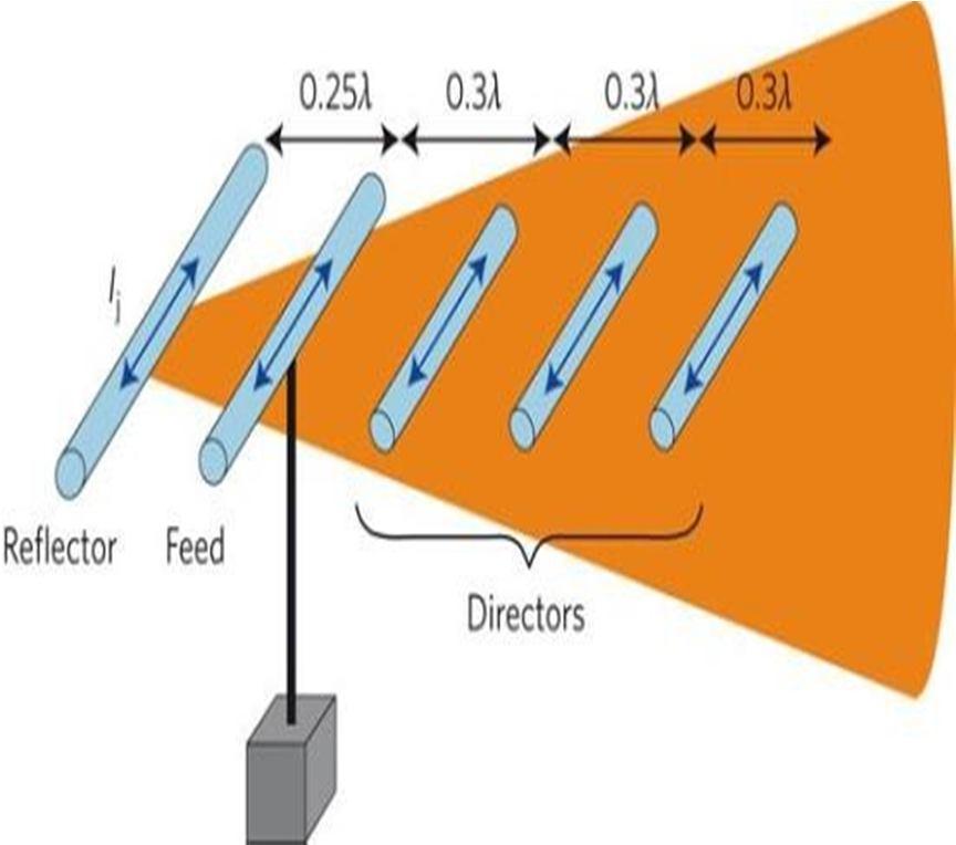
Yagi-UDA antenna has high directivity by applying current phase shifts between the elements due to resonance phenomena. There are directors and reflectors which are nonelectric elements. The director helps to improve the directivity of the yagi-UDA antenna. Turnstile antenna provides high directivity, several turnstiles may be piled up along a vertical axis. The main advantage of a parabolic antenna,it has high directivity. It functions similarlyto a flashlight reflector to direct radio waves in thin beam radio waves from one specific direction only.
Phased array antenna Directivity is the ratio of radiationintensity in a given direction from an antenna to the radiation intensity averaged over all directions. If that specific direction is not underlined, then the direction inwhich max intensity is observed can be taken as the directivity.
Yagi UDA antenna The structure of this directional antenna integrates three main parts which are directors,reflectors, and a feeder point of 50 Ω. The performanceof the proposed antenna has a tolerable reflection coefficient below -10 dB at 144.46 MHz. A maximum gain of around 14.03 dB with a good efficiency of75.6% is achieved.
Turnstile antenna the gain of a turnstile antenna isactually about 3 dB less than that of a single dipole in its direction of maximum radiation because each of theelements of the turnstile antenna receives only one-half the tx power.
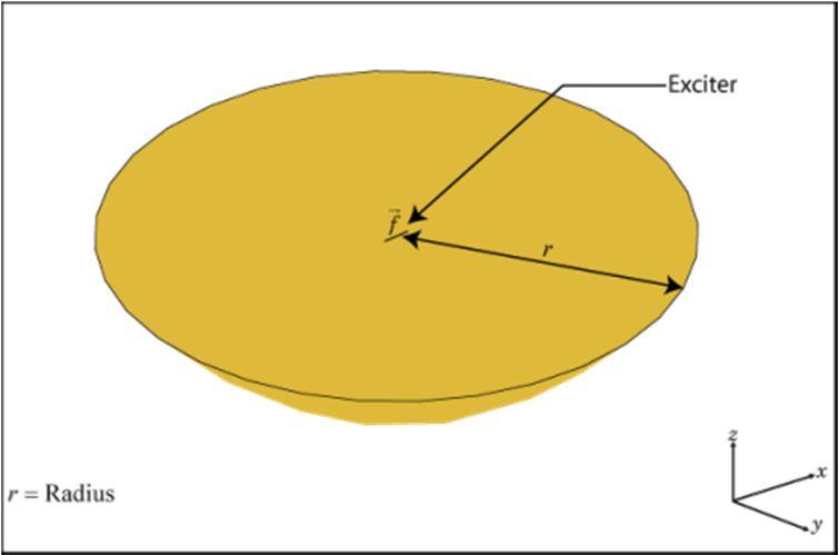
Parabolic antenna gain is calculated as the gain over an isotropic source, i.e. radiates equally in all directions.
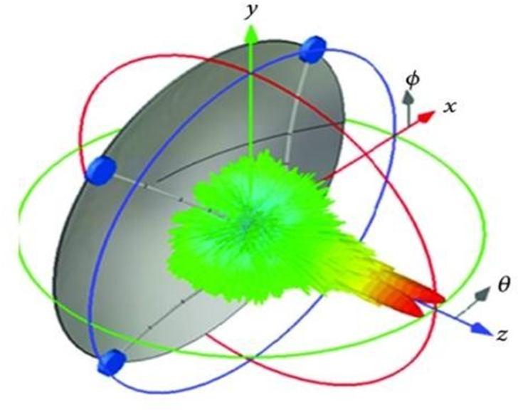
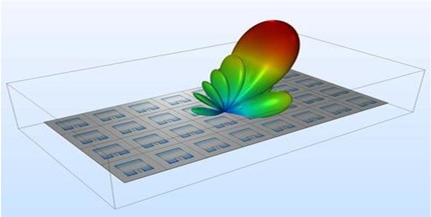
Phased antenna with a very large number of regularly- spaced radiating elements, the gain realized at the beampeak is equal to the number of elements times the gain realized in the same direction when only one element is excited. The ideal radiation pattern of one such element in a large planar array has a cosine variation of gain with an angle when the elements are closely spaced, and has a peak value of gain equal to 4\pi A/\lambda^{2} where A is the area allotted to eachelement. The active impedance of each element in a practical phased array varies with the scan angle, because of the mutual coupling between the elements. The associated mismatch causes power tobereturnedtothegenerators, therebyreducingthegainrealizedbythearray and by the element.
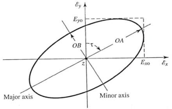
Since these three interpretations are related, theinterpretation of polarization for a vector at some pointin space and for a plane wave is part of the explanationof polarization of an antenna. The polarization to a vector is the shape, orientation, and sense of the ellipse that the extremity of the vector describes as a function of time. For polarization of a plane wave, the followingapplies, _In a singlefrequency plane wave a vector hasthesamepolarization at everypoint in space. Lastly, foran antenna, theterm polarization is used as follows. Thepolarization of an antenna in a given direction ofthe plane wave it radiates at huge distances in that direction. The polarization can be described as linear, circular, or elliptical. Linear and circular polarization can be seen as of elliptical polarization. The linear case is when the electrical vector at a point in space is a function of time points along a line.
ISSN: 2321-9653; IC Value: 45.98; SJ Impact Factor: 7.538 Volume 11 Issue I Jan 2023- Available at www.ijraset.com
The Yagi Uda antenna can radiate waves as both horizontal and vertical signals.
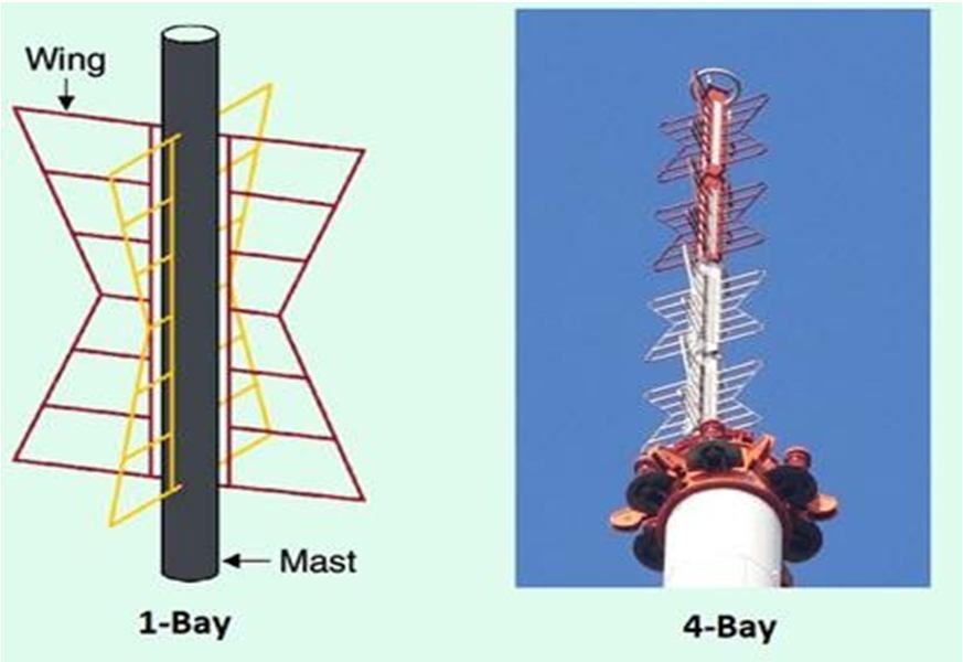
Two new turnstile antennas are described: 1) a horizontally polarized turnstile antenna and 2) a circularly polarized turnstile antenna. These antennas feature a rotating phase feed based on the original RCA Super turnstile design which, becauseof its simplicity, electrical characteristics, andversatility, is today the most popular TV broadcastantenna. Parabolic antenna polarization. The pattern of electricand magnetic fields at the front of a parabolic antenna is a scaled-up image of the radiation by the feed antenna, so the polarization is determined by the feed antenna. Phased array Dual Polarized (DP) Phased Array Radar (PAR) performance and cost are greatly influenced by the radiating elements selected and the architecture of the module. The performance can be dynamically optimized for a particular scan angle using prior knowledge of the characteristics of the radiating elements. The effectiveness of this strategy and the degree of difficulty in implementing it depends on major system decisions regarding scan volume, target objective (minimum detectable signal), and cost.
When it comes tosatellite communication, the groundstation and the satellite are definitively in each other far field. However, when antenna measurements are done at ground level if, for instance, a helical antenna were to be tested, the distance between the antenna and the receiver must be selected in such a manner that the measurements are done in the far _eld region.The radiation pattern consists of lobes of various sizes,the direction with the maximum radiation intensity is known as the major lobe or the beam of the antenna. The half-power beam width (HPBW)is measured. The HPBW is the angle between the two directions where radiation intensity has decreased to half of the maximum radiation. This angle is inversely proportional to the square of directivity or the gain andis a useful parameter when the gain is difficult to measure.
Ygai uda
ISSN: 2321-9653; IC Value: 45.98; SJ Impact Factor: 7.538 Volume 11 Issue I Jan 2023- Available at www.ijraset.com
Yagi-Uda antenna have high directivity as shown in the figure given below. Theminor lobes are reduced and the directivity of the major lobe is improved by the addition of directors Turnstile antenna
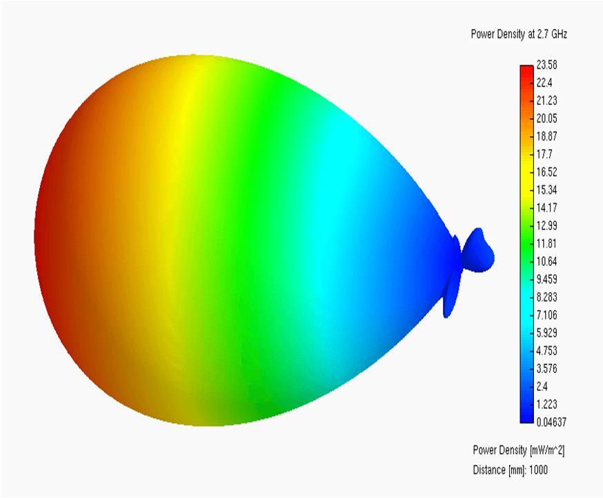
Theradiation pattern ofa parabolic antenna containsa major lobe, which is directed along the axis of propagation, and several small minor lobes. Very thin beams are developed with this type of reflector. Phased antenna
ISSN: 2321-9653; IC Value: 45.98; SJ Impact Factor: 7.538 Volume 11 Issue I Jan 2023- Available at www.ijraset.com
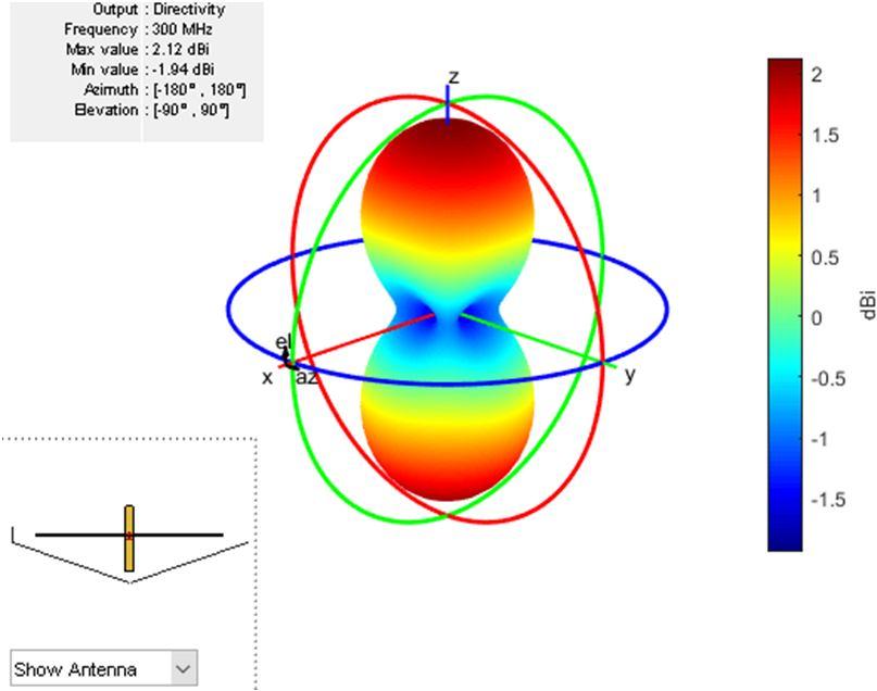
The radiation pattern will be similar to the radiation pattern of two superimposed dipoles. Though it is closeto an omnidirectional pattern, it leaves a cloverleaf- shaped pattern. Parabolic antenna
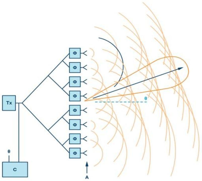
each element produces an equal output voltage of sin(ωt)sin(ωt).However, there will be an equal phase difference ΨΨ between successiveelements. Mathematically, it can be written as Ψ=2πdsinθλEquation1Ψ=2πdsinθλEquation1 Where, θ is the angle at which the incoming signal isincident on each radiation element.
Yagi UDA antennae are easy to install on the rotor mechanism and due to being lightweight it has low wind resistance and turning also required less power. The turnstile antenna is easy to install on the rotor butit has a little more wind resistance compared to the yagi UDA antenna. Parabolic antennae required a beam focused in the direction of reception of satellite signal so it will be difficult to accurately point it towards the satellite as the size increases the rotor cost also increases and it will be difficult to rotate. Phased antennae aregrp of antenna which is organizedin a pattern. As theyare grp it has high wind resistanceand rotation due to this load requiring a high-duty cycle. So it is not convenient to use this antenna.
Tomeet the requirements ofordinarymanagement andcontrol operation of future ultra-dense LEO satellite constellations, Yagi uda antennas are considered as attractive candidates thus supporting multiple satellitessimultaneously. Many advantages of yagi uda antennas have been recognized compared to traditionalreflector antennas in satellite ground stations, including better performance, higher reliability, and lower cost.
We are planning to make a yagi uda antenna as per allthe comparisons made, yagi UDA is reliable and best to use for automated tracking of Leo satellite, and thusin the future, we will make an AQQ controller which will require telemetric data of satellite and it will trackthe Leo constellation simultaneously and result wouldbe displayed
ISSN: 2321-9653; IC Value: 45.98; SJ Impact Factor: 7.538 Volume 11 Issue I Jan 2023- Available at www.ijraset.com
[1] P. Hannan, "The element-gain paradox for a phased-array antenna," in IEEE Transactions on Antennas and Propagation, vol. 12, no. 4, pp. 423-433,July 1964, doi: 10.1109/TAP.1964.1138237.
[2] M. Modaresi, L. Shafai and B. Lindmark,"Efficient optimization of a Yagi-Uda antenna using genetic algorithm," 11th International Symposium on Antenna Technology and Applied Electromagnetics [ANTEM 2005], 2005, pp. 1-4, doi: 10.1109/ANTEM.2005.7852127.
[3] H. Wang, Y. Xie and C. Zhang, "A Novel Circularly Polarized Yagi Antenna," 2018 International Conference on Microwave andMillimeter Wave Technology (ICMMT), 2018, pp. 1-4, doi: 10.1109/ICMMT.2018.8563320.
[4] Ben-Dov, "New Turnstile Antennas for Horizontaland Circular Polarization," in IEEE Transactions on Broadcasting, vol. BC-22, no. 1, pp. 1-5, March 1976, doi: 10.1109/TBC.1976.266187.
[5] M. Nagasaka, S. Nakazawa and S. Tanaka, "Dual-circularly polarized parabolic reflector antenna with microstrip antenna array for 12-GHz band satellite broadcasting reception," 2016 International Symposium on Antennas and Propagation (ISAP), 2016, pp. 692-693.
[6] R. M. Millan, R. von Steiger, M. Ariel, S Bartalev, M. Borgeaud, S. Campagnola, J. C. Castillo-Rogez, R.Fléron, V. Gass, A. Gregorio, D. M. Klumpar, B. Lal, M. Macdonald, J. U. Park,V. S. Rao, K. Schilling, G. Stephens, A. M. Title, and J.Wu, ``Small satellites for space science: COSPAR scienti_c roadmap,'' Adv. Space Res., vol. 64, pp. 1466_1517,Oct. 2019, doi: 10.1016/j.asr.2019.07.035.
[7] F. Davoli, C. Kourogiorgas, M. Marchese, A.Panagopoulos, and F. Patrone, ``Small satellitesand CubeSats: Survey of structures, architectures, and protocols,'' Int. J. Satell. Commun. Netw., vol.37, no. 4, pp. 343_359,2019, doi: 10.1002/sat.1277.