
10 IX September 2022 https://doi.org/10.22214/ijraset.2022.46881
ISSN: 2321 9653; IC Value:

ISSN: 2321 9653; IC Value:
Ramya S 1, Dr. Geena George 2
1PG Scholar, Dept of Civil Engineering, East Point College of Engineering and Technology, Bengaluru, 560049
2Associate Professor of the Dept of Civil Engineering, East Point College of Engineering and Technology, Bengaluru, 560049

Abstract: Designers and builders can simulate a physical environment using BIM, a type of digital technology, before starting actual construction. When developing and building things, various disciplines must work closely together. Each discipline is responsible for providing a unique contribution to the overall design. The objects from other disciplines may, however, occupy the same position in space or the same orientation when the incomplete designs are merged known as 'clash'. A collision of this nature is frequently discovered during construction, necessitating a significant amount of extra time and price. To avoid clashes in the final design, early collaboration is essential. BIM automation techniques can do this and perhaps reduce clashes by coordination of 3D Models. A case study that comprised clash detection between architectural, structural, and MEP BIM models was used to conduct the inquiry. The current study used Autodesk Navisworks Manage and Autodesk Revit as BIM tools to design capabilities to streamline and automatically discover clashes. The analysis of the case study data showed that BIM is a useful tool for identifying conflicts between building components. And an investigative study was done to know the reason why these clashes are created during modeling based on the questioners answered by BIM Modelers. The findings emphasize the need for greater transparency in partnerships where designers from varied backgrounds can work on projects simultaneously. This open and inclusive approach may have an impact on how architects, engineers, and construction professionals are trained in the future.
Keywords: Building Information Modelling (BIM), Mechanical Electrical Plumbing (MEP), Clash Detection, Revit, Navisworks.
Abbreviations
1) BIM Building Information Modelling
2) MEP Mechanical Electrical Plumbing
3) AEC Architecture, Engineering and Construction.
Building information modelling, or BIM, is rising in acceptance around the globe. Not only during the design and building stages, but also throughout the operation phase, BIM may have some clear benefits for a construction project. One of the main concerns for building projects is conflict and the early discovery of it. It takes time and requires the synthesis of remarkable design skills to manually find incompatibilities. In order to evaluate BIM's capacity for conflict detection throughout the design process relevant information is collected and structured in this project to enable a complete study of the details of construction. The 2D design layouts for the structural, electrical, and mechanical structures are among these specifics. This project is broken up into parts, with the first step consisting of identifying the source of clash incidence using an online survey. And for the project's second phase, a case study of residential construction has been selected. The study is measuring the efficiency of BIM for conflict detection using Autodesk products including AutoCAD, Autodesk Revit, and Autodesk Navisworks Manage for modelling.
1) Study on clash Detection benefits through BIM
2) Learn about the major reasons of clashes while BIM Modeling.
3) Analyze the nature of Clashes and its early identification through questionnaires from BIM Modelers.
4) Creation of 3D Model of different disciplines using Revit Software as follows;
a) Architecture
b) Structure
c) MEP (Mechanical, Electrical & Plumbing)

ISSN: 2321 9653; IC
www.ijraset.com
The
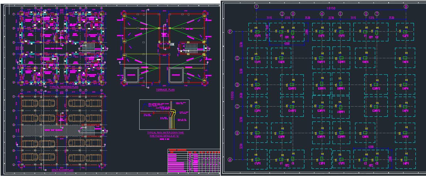
foundation of the original sketch design. The DWG file format is used for 2D plans. Initial
Auto CAD creates precise drawings in the 2D
which
were selected. Fig 1& 2 shows the respective
in 2D as depicted in the AutoCAD figures, were received from legal sources. For the purpose of
ISSN: 2321 9653; IC Value: 45.98; SJ Impact Factor: 7.538 Volume 10 Issue IX Sep 2022 Available at www.ijraset.com
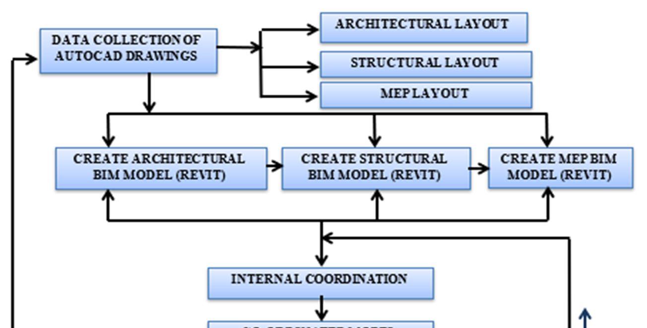
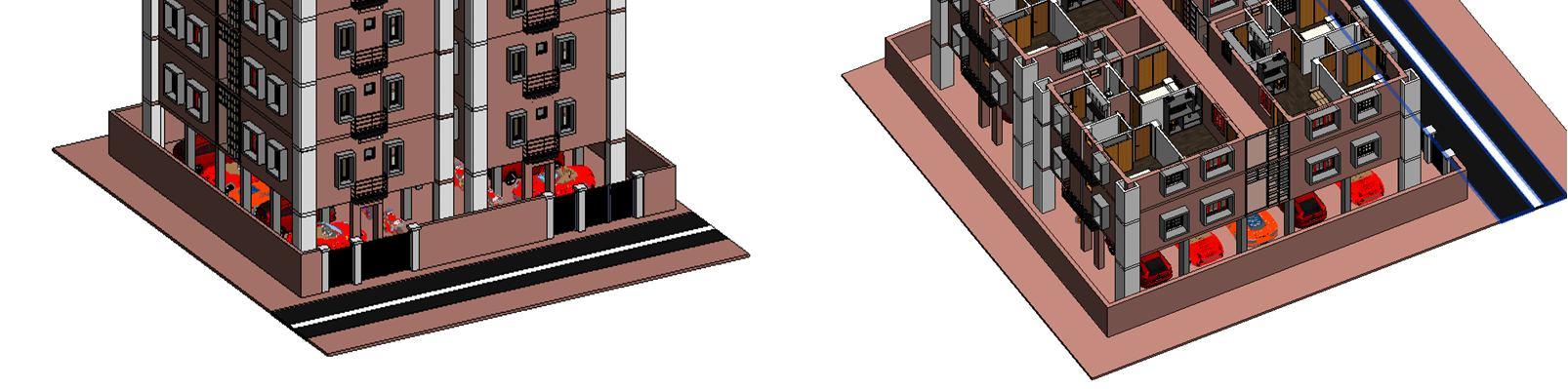
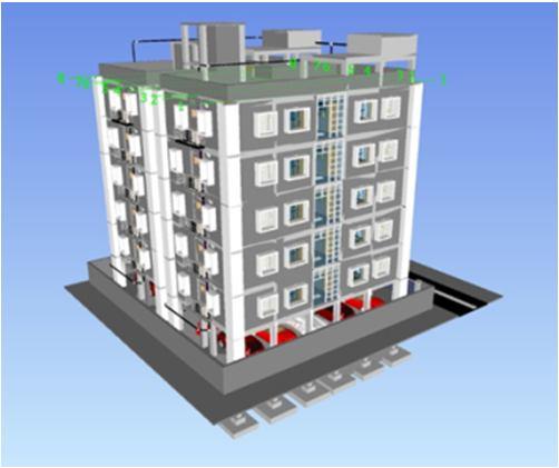
This project's model creation process was intended to create three dimensional models from simple two dimensional sketches. The project's eventual goal of conflict detection is taken into consideration when doing this. Various pieces of software are utilized for this, however in this case, Autodesk Revit 2020 is used. To do this, each level of the Arch Autocad 2D drawing layout is linked to Revit with the corresponding units taken into account in Autocad being maintained for the Revit model Based on this, the 2d layout specification is used to represent the components of the 3D model. The materials of all elements and sizes of the doors and windows must precisely match the specifications. Below figures shows the Architectural Modeling done in Revit;
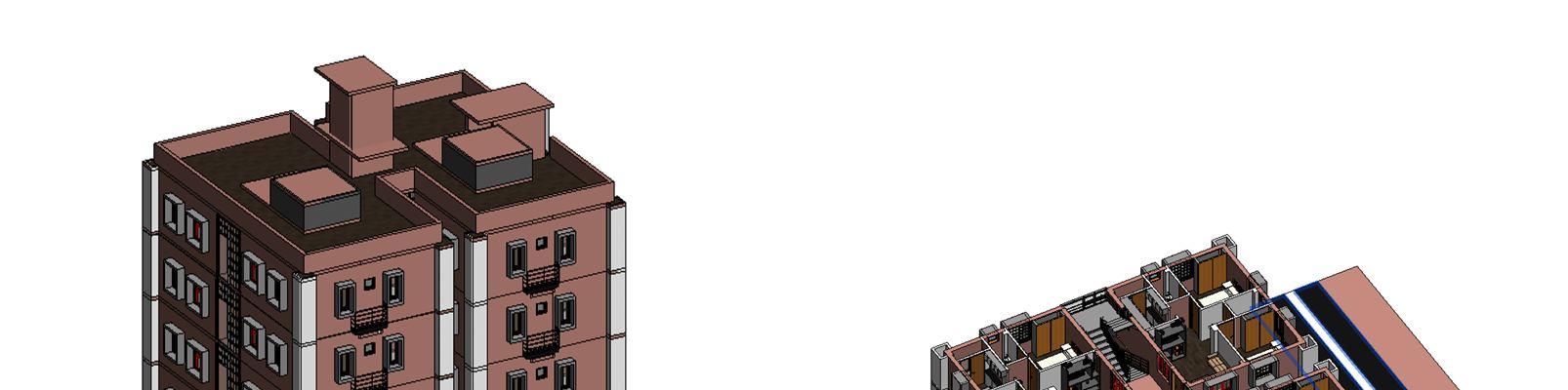
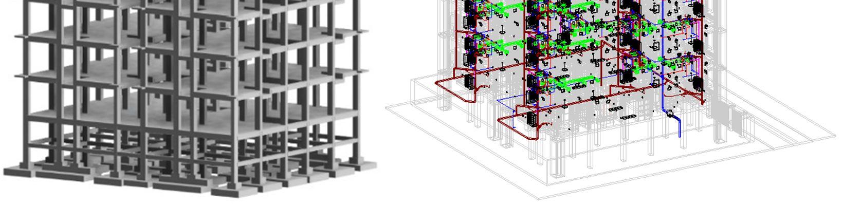
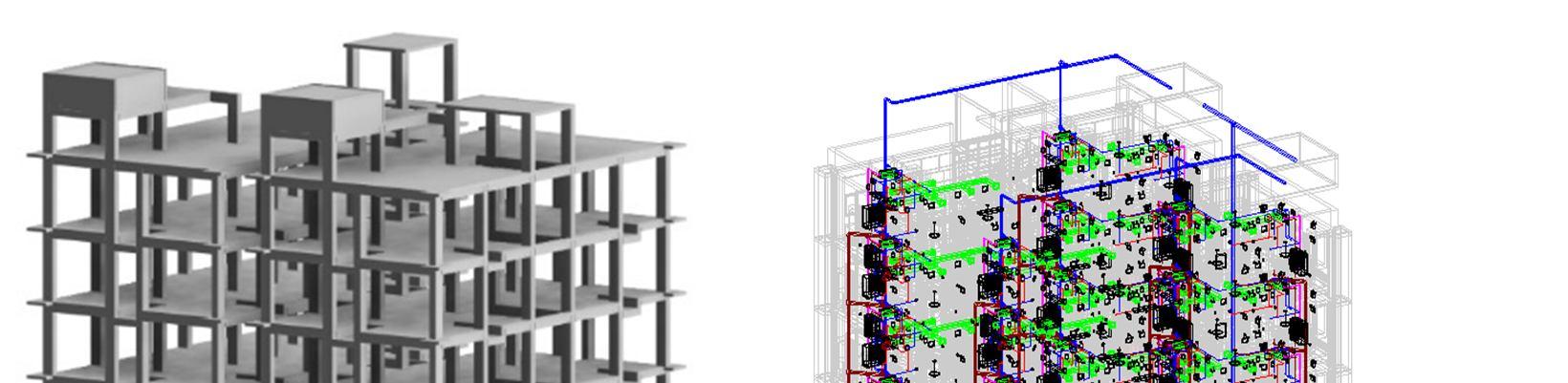
Based on the 2d drawings from AutoCAD, similar process of linking AutoCAD 2d for each level is done. In addition to it Revit arch model is linked. Both 2d drawings the 3d layout will fall in the same place giving it a baseline to model the structural element i.e., Slabs, beams, column, footing and load bearing walls are modeled. Since the features of the arch model have already been decided upon, it is quite unlikely that they will alter moving forward. Therefore, we had to align every element with the Arch model. Our objective was to provide the best solution to maintain such structure with good stability while keeping in mind that the requirement of the Arch model will mostly be about the aesthetic point of view. Fig 5 shows the structural model. Similarly, MEP (Mechanical, Electrical & Plumbing) All the three disciplines were modeled in the single model. Professionals who work in MEP engineering should use Revit MEP. Mechanical, Plumbing and electrical designs were implemented using Arch and structural model for MEP 3D modelling in Revit. Below Fig. represent the MEP Model. Fig 6 shows the MEP model
Science
Engineering Technology (IJRASET
ISSN: 2321 9653; IC Value: 45.98; SJ Impact Factor: 7.538
10 Issue IX Sep 2022 Available at www.ijraset.com
This documentation was ensured to reach each department to rectify any major changes. The majority of the case
Any clashes noticed while modeling
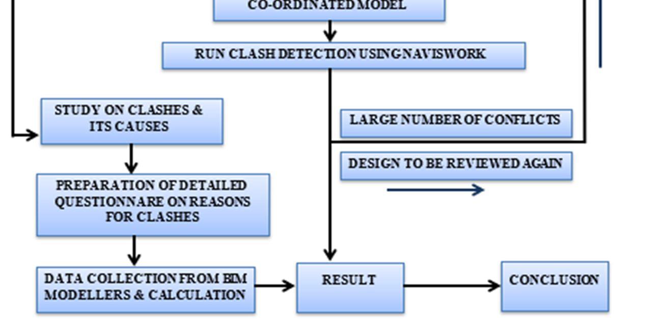
document was required the Arch or Structural element places clashing with MEP. This had to be further checked with clash detection software to know the intensity and the importance of clashes and the need for the particular change. Once there is a clear identification is done based on the reports the Internal coordination process to be carried out. After the three models are done, the files were exported as Nwc format of each file to Naviswork for clash detection to make a Co ordinated Model. Fig 7 shows the coordinated Model from Navisworks.

When using Autodesk’s Navisworks, a clash report is always generated between two design models. The Navisworks program was used to upload the first discipline's existing design model. Any two design models can be selected in order to produce potential conflicts between them in the coordinated model. Using Write Report option available in Navisworks it provides full report and
Select the necessary data required for the report and Write Report

While

photos that
Engineering Technology (IJRASET)
ISSN: 2321 9653; IC Value: 45.98; SJ Impact Factor: 7.538 Volume 10 Issue IX Sep 2022 Available at www.ijraset.com
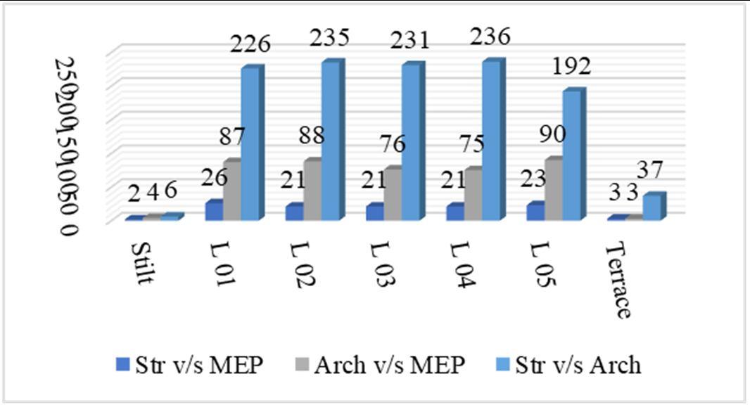
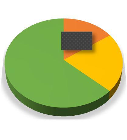
Based on the result, Fig 1 shows the maximum number of clashes are in structure and Architecture being 63%. This is mainly due to the minimum coordination that took place between Arch and structure as they were done parallelly. This shows that coordination is very crucial in the BIM modelling and it ill lead to majority of the clashes if unnoticed. And the others at 21% and 15% of Arch v/s structure and structure v/s MEP respectively. Level wise distribution of thee cashes are shown in Fig 9 this means that these models need multiple number of coordination before the issue of the drawings.
Table 2 illustrate the number of Clearance clashes that occurred in the clash detection test with the tolerance of 10mm. Clearance clash Verifies the minimal distance that must exist between two things. Majority of the clashes occurred in structure v/s Architecture. Total number of clashes are 10177. It is basically done to check the accuracy of the drawings.
Table 2. Clearance clash with tolerance 10mm
Structure v/s
Architecture v/s MEP Structure v/s Architecture
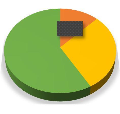
Figure 10 shows the percentage of clearance clash for all the levels. Similarly with respect to the hard clash the result shows that majority of it is in Structure v/s Arch at 59%.It is for similar reason as hard clash. By obstructing the space surrounding the object's physical volume, a soft collision may result. Instead of using the object's actual shape, the geometry is modelled based on the designer's perception. Sometimes the close proximity of two pieces will not allow for adequate building accessibility.
v/s
causing any disturbances.
reason for hard
Fig 10: Clearance clash (10mm) between three disciplines.
Table 3. Clearence Clashes with Tolerance 50mm
from

or more
in relation to other systems
for completion


result in serious
ignorant of a dimension or location
was done
International Journal for Research in
Science & Engineering Technology (IJRASET)
ISSN: 2321 9653; IC Value: 45.98; SJ Impact Factor: 7.538 Volume 10 Issue IX Sep 2022 Available at www.ijraset.com
It is crucial to understand the primary causes of conflicts that BIM professionals have when working in the BIM environment. The respondent was required to rate nine given reasons on a five point Likert scale question. The questionaries was sent through an online survey in terms of Google form for the BIM modellers to understand the reason why clashes occur. Below Table . Below are the question and the likart scale had option of choosing Strongly Agree, Agree, Disagree, Strongly Disagree and Uncertain as its options. And the results are in terms of Percentage. Total number of sent applications were 100 and the respondents were 48.
Table 4. Survey on Reasons for Clashes in BIM
Questionnaire
Strongly Agree Agree Strongly Disagree Disagree Uncertain
Due to Time Constraints 31.3 56.3 10.4 0 2 Due to Usage of Different File Formats by Different Teams of the Project 31.3 52.1 14.6 0 2
Inadequate Details on Object Modelling 35.4 60.4 14.6 2.1 2.1
Errors While Modelling the Design 20.8 54.2 16.7 4.15 4.15 Using 2D instead of 3D 29.2 52.1 14.6 2.1 2.1 Communication Issues Among Different team Members of Same Project 35.4 52.1 10.4 0 2.1
Scarcity of Skilled and Trained Professionals 18.8 70.8 8.3 0 2.1
Due to Design and Modelling Complexities 20.8 64.6 4.2 0 10.4
Due to Design Uncertainties 25 58.3 12.5 0 4.2 Balancing Between Model Accuracy versus Meeting the Deadline 27.1 64.6 8.3 0 0 Is it an Iterative Process? 16.7 72.9 6.3 0 4.1
Architectural Structural MEP Where Does Major Collison Occur? 18.8 33.3 47.9
Table 4 represents the major reason why the clashes happen while Modelling. The use of various file formats, a lack of time during the design stage a lack of appropriate object model information, and the complexity of the modelled objects are the primary causes of conflicts in the BIM tools. The outcome demonstrated that the computed values lack statistical significance. Reports state that construction companies encounter issues with data interchange since they do not adhere to a single neutral, interoperable standard. The process is iterative, there is a lot of back and forth required to reduce the number of clashes and make the model clash free. Major collision occurs in the MEP at 47.9% and with structural at 33.3%, the results of this as inconclusive in nature.The results highlight the need for greater openness during collaborations where designers from various backgrounds can work together concurrently to create.
In order to guarantee the quality of the BIM model that will be utilized in the following stages of the project lifecycle, this project describes the method of design clash detection, which is a component of a significant workflow of design coordination. If effectively used, the technique can assist designers in switching from clash detection to clash avoidance, which can result in significantly greater advantages. These findings demonstrate BIM's high level of accuracy and demonstrate how well it can be used to re document existing structures and identify conflicts between them. To show the workability that can be achieved by BIM enabled clash detection, the schema was developed using a qualitative and inductive research methodology (i.e., using literature and expert reviews).
Science & Engineering Technology (IJRASET)
ISSN: 2321 9653; IC Value: 45.98; SJ Impact Factor: 7.538 Volume 10 Issue IX Sep 2022 Available at www.ijraset.com
If the respondents in the initial sample group of 100 who did not answer to the survey had different viewpoints from those who did (46), there may have been an elevated likelihood of a non response bias. Under such conditions, extrapolating the results beyond the study's sample is frequently impossible. It was then validated by implementation on a case study of a significant Residential project. The schema involved identifying conflicts, categorizing conflicts, identifying typical conflicts within each category and its effects if they weren't resolved prior to construction. The findings showed that BIM Clash detection is a quicker, easier approach that also completely reduces the field of human errors during implementation. Design conflicts that arise within construction components are correctly identified by Navisworks. As the conflicts were not resolved between the three components to zero, the process need to be complete by the co ordination and then our system is ideal for use in a larger building project. The construction component collision detection was the main focus of this study. In order to resolve conflicts that have already occurred during building, more study is needed.
[1] Emad Kasra Kermanshahi1, Mahmood Bin Md Tahir, Nor Hasanah Abdul Shukor Lim, Ali Tighnavard Balasbaneh, Shervin Roshanghalb, (2020); “Implementation of Building Information Modeling for Construction Clash Detection Process in the Design Stage: A Case Study of Malaysian Police Headquarter Building”, “IOP Conf. Series: Earth and Environmental Science”, “IOP Publishing Ltd”.
[2] Jun Wang, XiangyuWang, Wenchi Shoua, Heap Yih Chong, Jun Guo, (2016); “Building information modeling based integration of MEP layout designs and constructability”, “Automation in Construction Volume 16”.
[3] Quan T Nguyen, Phuong Q Luu, Yen V Ngo, (2020); “Application of BIM in design conflict detection: a case study of Vietnam”, “IOP Conf. Series: Materials Science and Engineering”
[4] Racha Chahrour, Mian Atif Hafeez, Ahmad Mohammad Ahmad, Hashim Ibnauf Sulieman, Huda Dawood, Sergio Rodriguez Trejo, Mohamad Kassem, Khalid Kamal Naji, Nashwan Dawood (2020); “Cost benefit analysis of BIM enabled design clash detection & resolution”, “Taylor & Francis Journal”.
[5] Sanket D. Alone, (2020); “Clash Detection and Elimination using BIM”, “International Research Journal of Engineering and Technology (IRJET)”.