https://doi.org/10.22214/ijraset.2023.48754

ISSN: 2321-9653; IC Value: 45.98; SJ Impact Factor: 7.538

Volume 11 Issue I Jan 2023- Available at www.ijraset.com

https://doi.org/10.22214/ijraset.2023.48754

ISSN: 2321-9653; IC Value: 45.98; SJ Impact Factor: 7.538

Volume 11 Issue I Jan 2023- Available at www.ijraset.com
Abstract: Precast concrete segmental bridges (PCSBs) have been the most common design technology used in the last decades. In these studies Non-linear structural performances of externally prestressed, precast concrete segmental bridges (PCSB). PCSBs with externally prestressed tendons have become very popular in construction because of economical and safety reasons, fast and practical construction, and outstanding serviceability. External tendons technique is widely used because it allows to inspect the cables and to replace them or to reinforce the tendons in case of damage while such kinds of actions are difficult to be taken in case of internal prestressing. It is widely recognized that segmental bridges have better durability, lower life-cycle costs and higher quality for maintenance than other types of bridges. However, there is lack of reliable computational model for analyzing behavior of post-tensioned PCSBs. Experimental analysis of bridge segment required more cost, time and effort for the analysis and also take cake of quality of material, cast process, curing, and testing.
This research presents the results of stress and strain state of the local bearing area caused by a Prestressed cable anchor in reinforced concrete bridge segment. Nonlinear analysis of anchorage and rebar, concrete segment can be carried out by analytical solution calculated with the reference of ACI 318/19. ANSYS software is used for model and analyze the structure. The analysis process was carried out in 3 types : linear elastic analysis, nonlinear elastic analysis, and nonlinear analysis considering the destruction of concrete, and the value is compared with ANSYS software ( static structure).
In reinforced concrete and prestressed concrete, steel reinforcement is used to resist the tensile forces and stresses in the concrete. In prestressed concrete, compression is introduced in concrete elements to increase load capacity and improve behavior. The beneficial effects of prestressing have lead to the development of long span structures, especially long span bridge structures. There are two methods for prestressing concrete: pre-tensioning and post-tensioning. In pre-tensioning, prestressing steel (either rods or strands) are stressed (stretched), held in place, bonded to concrete which is cast after the steel is stressed, and released after the concrete reaches a specified strength.
When the prestressing steel is released, compressive force is applied to the concrete. Typically, as long as the concrete strength is strong enough to withstand the compressive stresses that develop when the load is applied, pre-tensioning increases the tensile capacity of the structural member.

Fueled by the desire to erect bridges with longer clear spans and smaller cross-sections, engineers introduced design and construction innovations such as segmental box girder bridge construction. In segmental box girder bridge construction, posttensioning is used to connect individual bridge segments together to create bridge spans. In post-tensioning, concrete elements (i.e. bridge segments) are cast with embedded post-tensioning anchorage devices. When the segments are assembled, prestressing steel (most commonly steel strands) are threaded through the anchors and ducts, stressed and locked in place. As a result, large compressive forces are introduced in the bridge segments at and near the anchors.
If the post-tensioned anchorage zone is not properly detailed and designed to withstand the forces and stresses which develop, failure of the anchorage zone can occur. If there is inadequate confinement reinforcement in the local zone (the vicinity immediately surrounding the anchorage device) cracking, crushing and spalling of concrete may occur.
To prevent failure in the anchorage zone, non-prestressed (or mild steel) is used to resist the tensile stresses. Due to the large forces active in the anchorage zones much mild steel is required. Steel congestion in the area may lead to problems related to poor concrete consolidation.

ISSN: 2321-9653; IC Value: 45.98; SJ Impact Factor: 7.538
Volume 11 Issue I Jan 2023- Available at www.ijraset.com
The main objective of this research was to investigate the use of steel fiber reinforced concrete (SFRC) in post-tensioning (PT) anchorage zones of bridge girders. The purpose of using SFRC is to enhance the overall performance and to reduce the amount of steel rebar required in the anchorage zone. Reducing steel congestion in post-tensioning anchorage zones can improve the constructability of post-tensioned bridge elements.
Results from an investigation by Haroon (2003) showed that the use of SFRC improved the local zone capacity and provided a reduction in secondary mild reinforcement. It was the intent of this study to consider both the behavior of the local zone and the general zone when steel fiber reinforced concrete is used. Also, It was desirable to implement a test program that considered material stress levels that are similar to those typically found in post-tensioned bridge members (such as concrete post-tensioned segmental box girders).
To achieve the objectives of this study, both experimental and analytical investigations were conducted aiming at reducing the amount of mild steel reinforcement required by the AASHTO code at the anchorage zone. The experimental part of the study involved laboratory testing of twenty-seven samples representing typical anchorage zone dimensions in post tensioned girders. The analytical study was conducted using non-linear finite element analysis in order to have a comprehensive stress analysis of the anchorage zones with and without fiber reinforcement and mild steel reinforcement. Inherent in the objective is the determination of the proper ratio of steel fibers that can be used without jeopardizing the constructability of the anchor zone. Meeting the objective of this study resulted in the development of a rational method to analyze and design the local and general zones reinforced with steel fibers.
As per the limitations obtained from literature review in the field of research, the problem statement and methodology that is required to fulfil the research work are discussed in the following sections.

This research work is aimed to find the analytical value of strut & tie of bridge segment as per ACI 318/19. The dimensions of bridge segment is shown in fig 4.1. The analytical value are obtain from the hand calculations were validated with the software value by using ANSYS Static software for analysis.
In this study, Analytical and Software both analysis were carried out with reference of ACI 318/19 code of practice. Analysis of the bridge Segment was calculated the following parameters with the data from the research paper of Takebayashi, Post-tentioning anchorage, strut and tie and the analysis process was carried out in 3 types : linear elastic analysis, nonlinear elastic analysis, and nonlinear analysis considering the destruction of concrete. The results were validated by compare with the software analysis results using ANSYS software.
A bridge segment is chosen, modeled and thoroughly analyzed under post tensioned loading conditions similar to what are encountered in the field. The purpose this analysis is to define the extent of the post-tensioning stresses around the anchorage zones in a full scale mode. Such a step is necessary to delineate the boundary conditions of the anchorage zone if smaller sections were to be considered.
Constitutive properties for finite element modeling including compressive strength, tensile strength. After the full scale analyses of the bridge segment, a scaled block containing two posttensioning anchors are separated from the web area of the bridge segment. This block is then analyzed using three dimensional finite element modeling to determine the boundary conditions at which stress distributions were not affected by the length of the block.
Once the geometry was input, the necessary properties of the segment had to be input in ANSYS. The necessary properties involved choosing the element that would be used to mesh the segment along with defining the material properties of the segment. The segment consists of concrete (with reinforcing steel), steel anchorages, and steel ducts. A complete list of the required material properties is provided in Table below.
Analytical solution of strut and tie is shown as per table from ACI 318/19


ISSN: 2321-9653; IC Value: 45.98; SJ Impact Factor: 7.538
Volume 11 Issue I Jan 2023- Available at www.ijraset.com


ISSN: 2321-9653; IC Value: 45.98; SJ Impact Factor: 7.538

Volume 11 Issue I Jan 2023- Available at www.ijraset.com
As per guidelines given in ACI 318/19 solution are find out by given formula.

fc' = 50 MPa
fy = 420 MPa
Phi = 0.75 for both strut and tie
Beta-s = 1.0
Beta-c = 1.0

Strut strength = Phi x 0.85 x Beta-s x Beta-c x fc' = 0.75*0.85*1.0*1.0*50 = 32 MPa
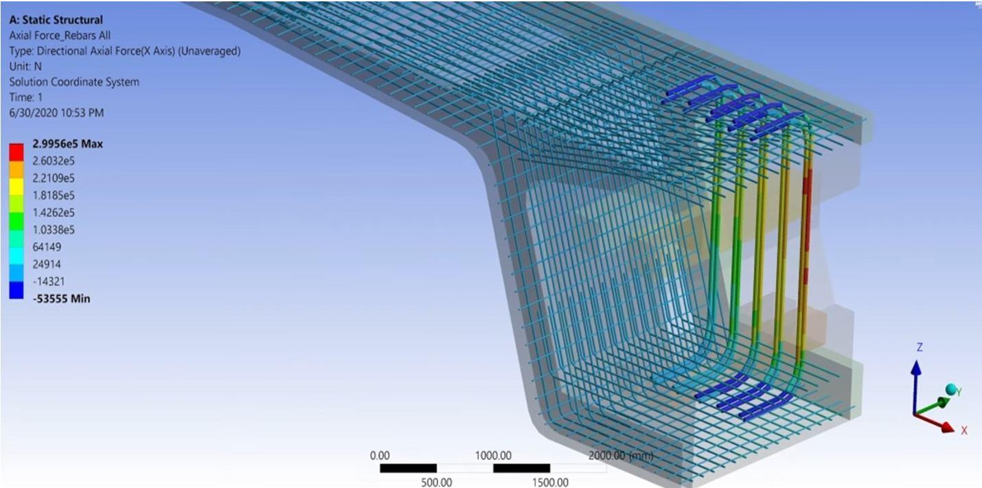
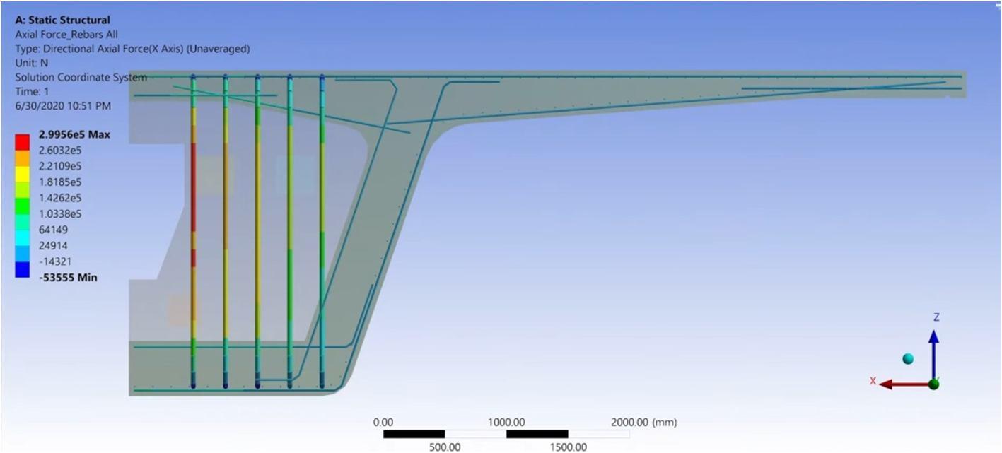
Tie Strength for rebar diameter 40 mm = Phi x fy x As = 0.75*420*pi()*40^2/4 = 395,840 N


ISSN: 2321-9653; IC Value: 45.98; SJ Impact Factor: 7.538
Volume 11 Issue I Jan 2023- Available at www.ijraset.com

A. General
In this ANSYS model after run the Analysis, we found the results of the models are shown with pictures below.


ISSN: 2321-9653; IC Value: 45.98; SJ Impact Factor: 7.538


Volume 11 Issue I Jan 2023- Available at www.ijraset.com


ISSN: 2321-9653; IC Value: 45.98; SJ Impact Factor: 7.538


Volume 11 Issue I Jan 2023- Available at www.ijraset.com


ISSN: 2321-9653; IC Value: 45.98; SJ Impact Factor: 7.538

Volume 11 Issue I Jan 2023- Available at www.ijraset.com


ISSN: 2321-9653; IC Value: 45.98; SJ Impact Factor: 7.538


Volume 11 Issue I Jan 2023- Available at www.ijraset.com


ISSN: 2321-9653; IC Value: 45.98; SJ Impact Factor: 7.538
Volume 11 Issue I Jan 2023- Available at www.ijraset.com


ISSN: 2321-9653; IC Value: 45.98; SJ Impact Factor: 7.538
Volume 11 Issue I Jan 2023- Available at www.ijraset.com

1) This research suggests that Prestressed cable anchor can be used successfully to reduce steel congestion in the anchorage zone without decreasing the capacity of the member.
2) Based upon this research, It is recommend that confinement reinforcing (spirals) be used in the local zone and bursting steel (steel ties) be used in the general zone. However, the spacing of this steel can be increased above the current design recommendations and the current ACI 318/19 recommendations for the approximate design method.
3) Based upon the load test results for the parameters used in the test specimens, it was possible to double the tie spacing for the bursting reinforcement.
4) This behavior of test segment over the complete analysis confirms the adequacy of design.
5) The segment showed substantial ductility in deflection and joint opening, structure with post tensioned will give sufficient warning before failure.
[1] ACI Building Code Requirements for Structural Concrete (2019).
[2] Anchorage Zone Reinforcement for Post-Tensioned Concrete Girders, National Cooperative Highway Research Program Report 356, Washington D.C. (1994).
[3] Prestressed Concrete Structures Englewood Cliffs: Prentice-Hall (1991).
[4] Anchorage Zones in Post-Tensioned Concrete Structures, The University of Texas at Austin (1992).
[5] Analytical Modeling of Fiber Reinforced Post-Tensioned Concrete Anchorage Zone, Florida State University (2006).
[6] Analysis and Design of Anchorage Zones in Post-Tensioned Concrete Bridges, The University of Texas at Austin.Hanson, (1990).
[7] Beams with openings under different stress conditions, Conference on Our World in Concrete and Structures, Singapore, (1977).
[8] Post-Tensioned Bridge Girder Anchorage Zones Enhancement With Fiber Reinforced Concrete (FRC), (2004).
[9] ANSYS, ANSYS User’s Manual Release 11, ANSYS, Inc.
[10] Application of Fiber Reinforced Concrete in the End Zones of Precast Prestressed Bridge Girders (2002).
[11] Behaviour of patch repair of axially loaded reinforced concrete beams, Cement & Concrete Composites 28 (2006).
[12] Finite element analysis: theory and application with ANSYS (2008).

[13] Tendon corrosion in precast segmental bridges,Transportation research record, Transportation Research Board, Washington, D.C. (1999).
[14] Modified skew bending model for segmental bridge with unbonded tendons, ASCE (2006).

[15] Structural behavior of single key joints in precast concrete segmental bridge (2007).
[16] Dry joint behavior of hollow box girder segmental bridge(2004).
