1 minute read
International Journal for Research in Applied Science & Engineering Technology (IJRASET)

from Multifunctional Control for PV Integrated Battery Energy Storage System with Enhanced Power Quality
by IJRASET


ISSN: 2321-9653; IC Value: 45.98; SJ Impact Factor: 7.538
Advertisement
Volume 11 Issue III Mar 2023- Available at www.ijraset.com
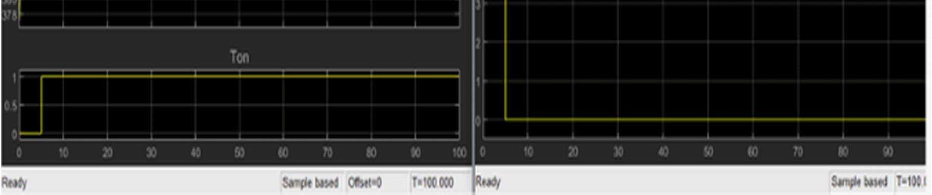
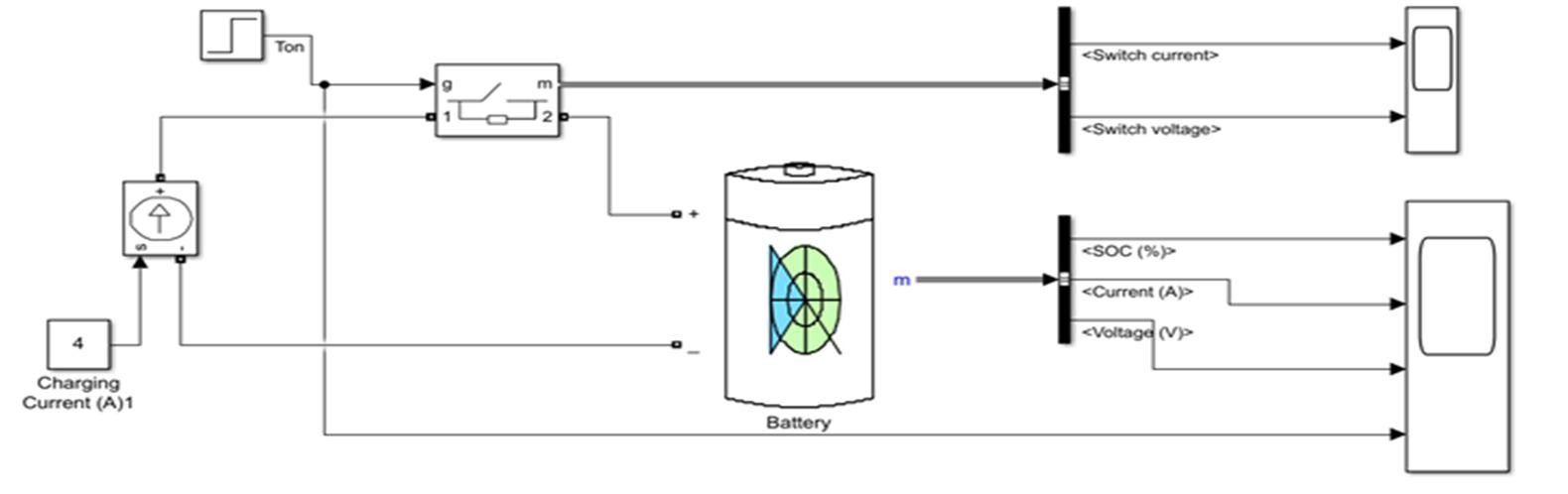
Figure11. Shows the Simulink model of Multifunctional Control for PV Integrated Battery Energy Storage System. Operating mode 1: when the grid and the PV generated the same powers to the load between t = 0 to 0.5 s assuming the PV power generating system is greater than the difference between the load and the grid power (PPV ≥ PLoad − Pgrid) and assuming the battery is not fully charged. The excess power of the PV array also simultaneously charges the battery bank. Battery SOC as shown in Fig. 12. Operating mode 2: when (PLoad ≥ 0.11 MW) the PV generated the nominal power to the load so the grid supplies power to the grid between t = 0.5...1 s, in this mode,the battery is able to provide power to ensure the stability of the DC-link voltage. Operating mode 3: when (PLoad ≤ 0.11 MW) the grid supplies power to the grid between t = 1...1.5 s . In this mode, the PV panels can simultaneously supply to power to the load, to the battery and to manage the DC-link voltage of the three-level NPC inverter
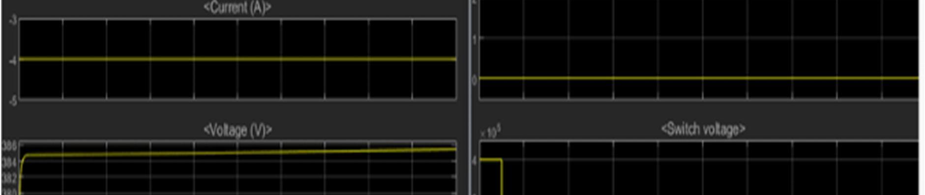
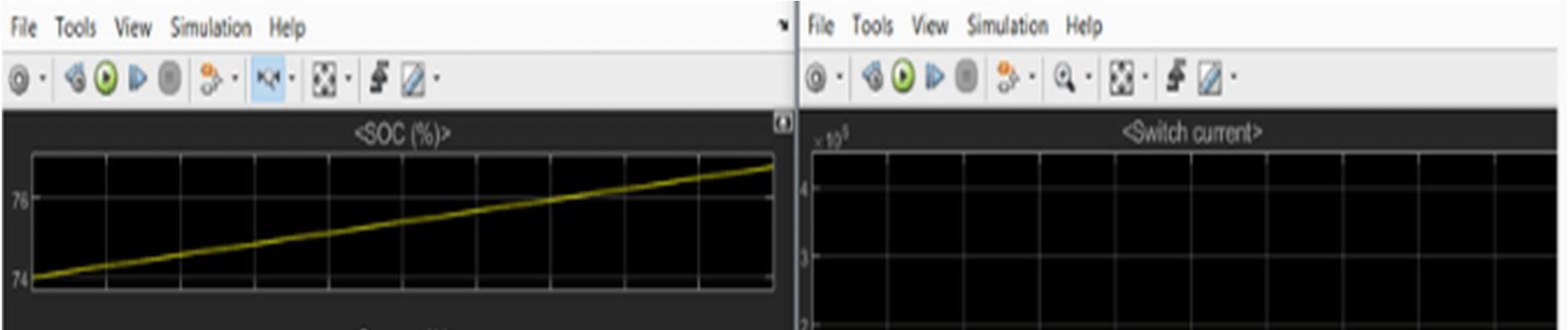
V. SIMULATION RESULTS
The SOC of a battery, that is, its remaining capacity, can be determined using a discharge test under controlled conditions. The voltage method converts a reading of the battery voltage to the equivalent SOC value using the known discharge curve (voltage vs. SOC) of the battery. The battery minimum state of charge is the relative state of charge below which the storage bank is never drawn, specified as a percentage of the total capacity. Most rechargeable batteries are not meant to be fully discharged. In fact, fully discharging some batteries can permanently damage them


