8 minute read
Multifunctional Control for PV Integrated Battery Energy Storage System with Enhanced Power Quality

from Multifunctional Control for PV Integrated Battery Energy Storage System with Enhanced Power Quality
by IJRASET

B. Murali Mohan1, S. Gurucharan2, V. Achyuth Reddy3, P. Balaji4 , B. Karthik Kuma
1,2,3,4 Electrical and Electronics Engineering Department, Annamacharya Institute of Technology & sciences, Rajampet, Andra Pradesh, India
Advertisement

Abstract: This modest paper presents a study on the energy quality produced by a multifunction system consisting of a Photovoltaic (PV) power source connected to a battery. A three-level inverter was used in the system studied for the purpose of improving the quality of energy injected into the grid and decreasing the Total Harmonic Distortion (THD). A Maximum Power Point Tracking (MPPT) algorithm based on a Fuzzy Logic Controller (FLC) is used for the purpose of ensuring optimal production of photovoltaic energy. In addition, another FLC controller is used to ensure DC bus stabilization. The considered system was implemented in the Matlab/Simpower environment. The results show the effectiveness of the proposed inverter at three levels in improving the quality of energy injected from the system into the grid.
I. INTRODUCTION
Global interest in clean and renewable energy sources (RESs) has been growing exponentially. Solar energy is gaining in importance as a renewable source due to advantages such as low maintenance, no noise, no fuel cost, and low wear and tear due to the absence of moving parts [1– 6]. The energy conversion efficiency of a PV array is low and varies with solar intensity and operating temperature [7]. The tracking control of the maximum power point is a key and complex issue. Therefore, to achieve the maximum efficiency possible, Maximum Power Point Tracking (MPPT) control is critical to the success of PV systems. To mitigate the problems involved, various tracking control strategies have been discussed in past literature with a view to obtaining maximum energy conversion efficiency of the PV array for all operation conditions, such as perturb and observe [3, 8] and incremental conductance [8–11]. These strategies have disadvantages such as difficulty, high cost, instability and complexity. To overcome these disadvantages, several researchers have used artificial intelligence approaches such as Fuzzy Logic Controller (FLC) [6, 12–17] and Artificial Neural Network (ANN) [18–22] to obtain maximum energy conversion efficiency. This study discusses the FLC method to deliver MPPT for a PV system. Fuzzy logic is robust and relatively simple to design, since it does not require information regarding the exact model or load level. Another element that plays a very important role in solar generation power systems is battery storage [2, 17].
Batteries are used to store superfluous energy derived from solar irradiance on sunnydays and for release on cloudy days or at night. Battery technology has made considerable advances, the rechargeable battery has been upgraded from a lead acid battery to a nickel-based batteryand from a nickel-based batteryto a lithium-ion (Li-ion) battery. Nowadays, Li-ion batteries are widelyadopted in portable electronic devices, such as smart phones, digital cameras and laptop computers. Lithium-ion batteries enjoy higher energy density, higher terminal voltage and higher power density than other rechargeable batteries. This study integrated a PV system with a Li-ion battery charging system connected to the grid via a three-level neutral point clamp (NPC) inverter. Multilevel converters are considered to be the most suitable power converters in renewable energy applications, especially in developing highpower generators [6]. Multilevel converters present many advantages when compared with the standard two-level conventional converters, such as improved output voltage waveform, reduced harmonic content, increased power rating, and decreased stress across the switches. However, their main disadvantage is the balancing of the capacitor voltages in the DC link [3].
II. MODELLING OF THE PV-BATTERY SYSTEM
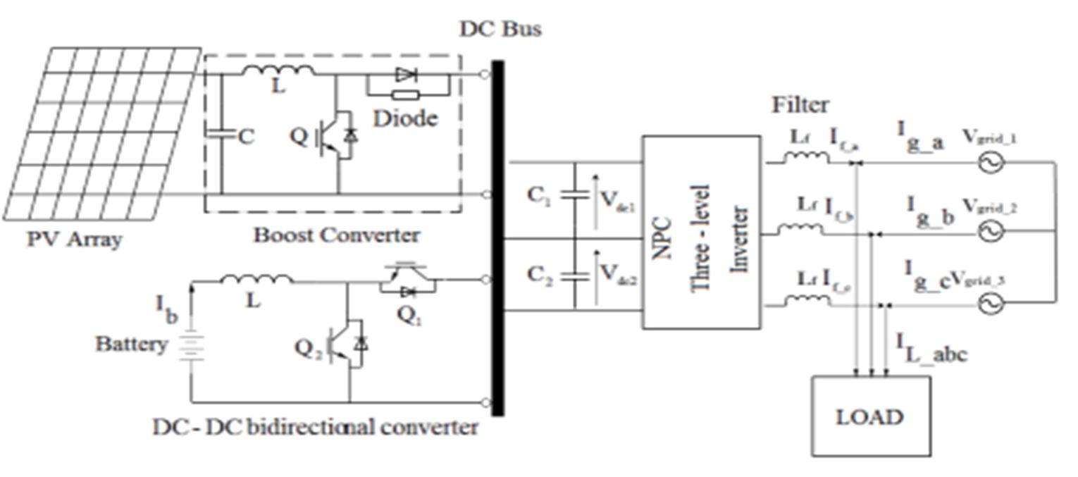
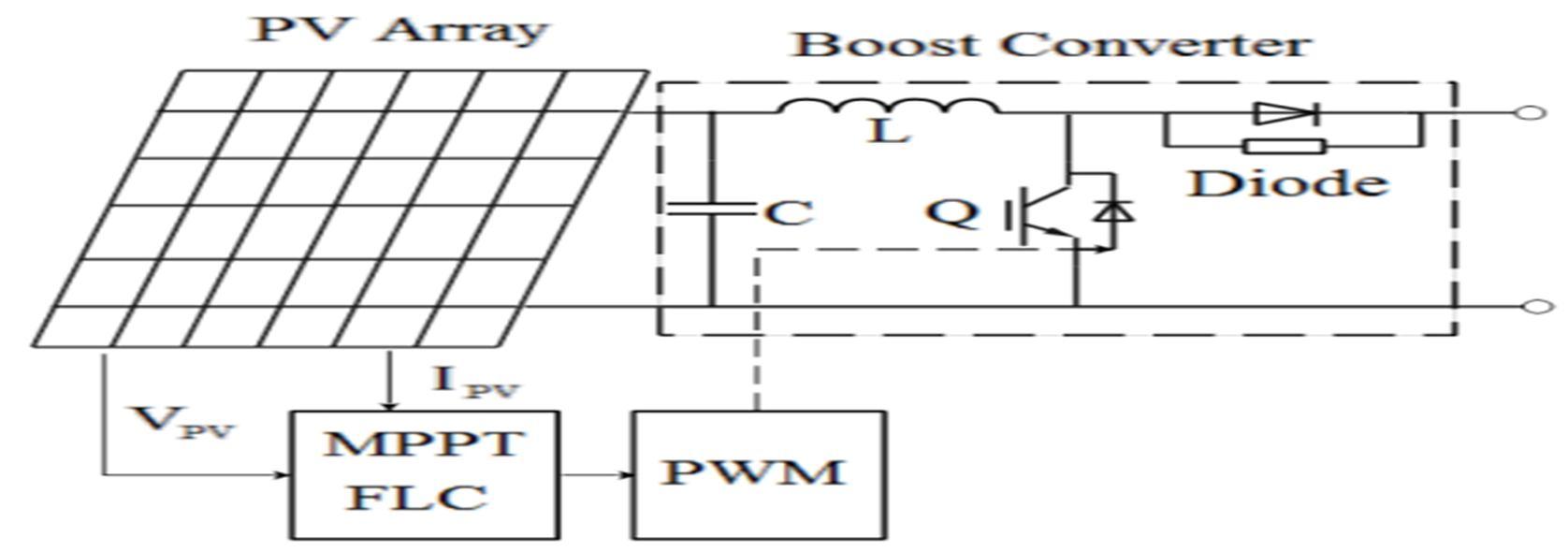
The proposed grid-connected PV-battery system is shown in Fig. 1. The PV array is connected to the DC bus via a boost converter controlled by a MPPT algorithm to extract the maximum power. The DC bus is then connected to the AC bus through the NPC three-level inverter.
ISSN: 2321-9653; IC Value: 45.98; SJ Impact Factor: 7.538
Volume 11 Issue III Mar 2023- Available at www.ijraset.com
The battery is connected to the DC link through a DC-DC bidirectional converter and contributes to the regulation of the DC link voltage and to power balance the supply and demand of power. A small L- filter is connected with the inverter output to eliminate high frequency harmonics.
A. Modelling of the PV System and Design of MPPT Control Strategy
The electric power generated from the PV array fluctuates with the operating conditions and field factors such as the sun’s position angle, irradiation levels and ambient temperature
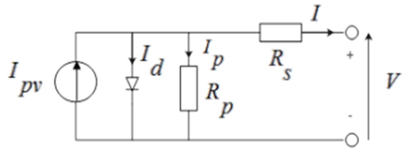
A solar cell can be represented as a current source model, as shown in Fig. 2. Applying Kirchhoff’s current law, the terminal current of the cell is [4]:
I = Ipv − Id − Ip (1)
Ip = V + RsI/ Rp (2)
The light generated current of the PV cell depends linearly on the solar irradiation and is also influenced by the temperature according to the following equation (3)
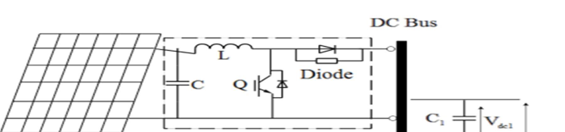
Fig. 3 shows the basic circuit configuration of a DC-DC boost converter with an MPPT controller. A capacitor is generally connected between PV panel and the boost circuit to reduce high frequency harmonics [36]. MPPT algorithms have been proposed to automatically find the PV panel operating voltage that produces the maximum power output. Several MPPT techniques exist in the literature ranging from the simplest methods such as Perturb & Observe [3, 8] and Incremental Conductance [8, 9] to more sophisticated and complex ones. In this paper, an MPPT algorithm based on fuzzy logic control (FLC) is proposed. Similar FLCbased MPPT controllers were proposed in [6, 17]. The basic scheme of a FLC is shown in Fig. 4.
B. Maximum Power Point Tracking (MPPT)
ISSN: 2321-9653; IC Value: 45.98; SJ Impact Factor: 7.538
Volume 11 Issue III Mar 2023- Available at www.ijraset.com
The inputs are the error E and error change dE; the output is the PWM duty cycle variation dD. Where KE, KdE and KdD are scaling gains selected to achieve the desired transient and steady-state response characteristics [6, 12–14, 16]. The universe of discourse for each input and output variable is divided into three fuzzy sets defined by triangular membership functions and labelled as NS (Negative Small), Z (Zero) and NB (Negative Big) as shown in Fig. 5. The fuzzy rules used to determine the controller output. The defuzzification is based on the popular center of gravity method.
C. Impact of Irradiance and Cell Temperature
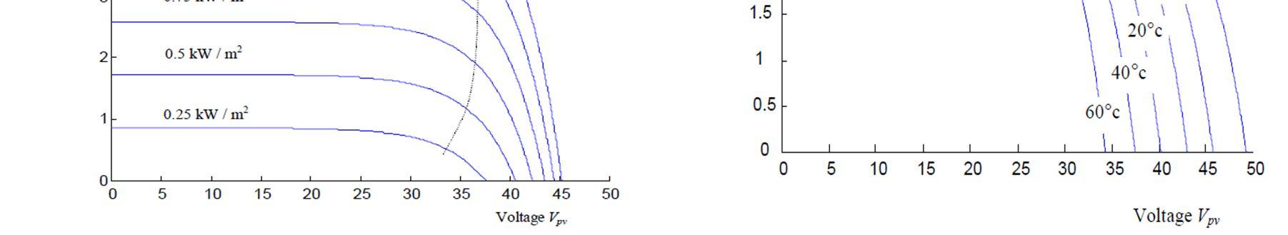
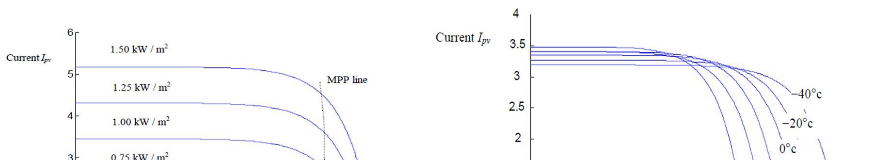
The impact of irradiance and cell temperature on Ipv-Vpv characteristic function is demonstrated in figures 4 & 5, separately in figure 4. Demonstrates that the energy resultant changes straight with the irradiance. Figure 5. Demonstrate that the utmost resultant energy from the cluster diminishes in light of the fact that the temperature increments.
D. Power Stage in Boost Converter
Figures 6 shows improved forms of both the boost and buck converters. Just the force stage is appeared; a total controller requires more hardware to direct the result. We will begin by taking a gander at the buck. Note that single side of the inductor is associated with yield hub. Since no DC current can course through the yield capacitor, the complete burden current moves through the inductor. The alternative side of the inductor is linked to the regular hub in middle of the MOSFET and diode.
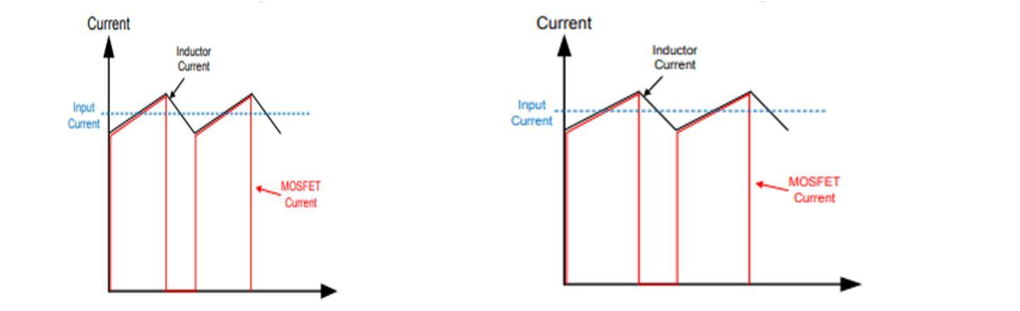
Figures 7 & 8 shows that the inductor and MOSFET current in CCM. On and off chance that we maintain a strategic distance from the, little three-sided swell, it is easy to see that the pinnacle MOSFET current is virtually similar as the heap current. This makes it simple for the controller producer to define the utmost burden current that the controller can flexible. Not with standing of the i/p or o/p V, the MOSFET can be measured for the most noteworthy burden current.
ISSN: 2321-9653; IC Value: 45.98; SJ Impact Factor: 7.538
Volume 11 Issue III Mar 2023- Available at www.ijraset.com
Likewise, as far as possible the present limits are often arranged just above this utmost value. So, the utmost MOSFET current rating of a buck is that the greatest burden current rating. As an illustration the LM43603 is evaluated for 3A on the info sheet. This is the utmost load I for this gadget. This isn’t the situation for a lift converter. Note from figures 6 that the inductor is associated from the info supply to the normal hub between the MOSFET and diode. Along these lines the height MOSFET current is presently almost adequate to the info current, not the heap current. We will see that the info I relies upon the info and yield V’s of the converter. The boost regulator remains rated supported the utmost MOSFET current but this doesn't represent the utmost load current, like the buck. The easiest approach to measure the information I of a boost controller is to utilize the energy balance condition.
For a DC/DC converter, the i/p and o/p energies are only the merchandise their particular I’s and V’s. Adding the 3-sided ripple current, we show up at below equation 5.
A. Li-Ion Battery Model
III. BATTERY ENERGY STORAGE SYSTEM (BESS)
The modelling approach is based on the equivalent circuit of the battery shown in Fig. 9. Where R represents the conducting resistance and the resistance from leading wires, R1 and C1 represent effects caused by mass transport, R2 and C2 represent effects caused by the charge transfer and the electrochemical double layer. The model will therefore include a State of Charge (SOC) controlled voltage source and its equivalent impedance.

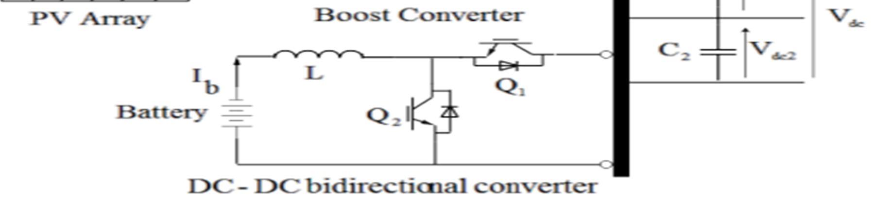
B. Battery Control System
The objective of the control system is to regulate the battery current in order to obtain the required power. Charging and discharging current limits and maximum SOC limitations are also included in the model. The BESS is connected to the DC grid via a bidirectional Buck-Boost DC/DC converter, as shown in Fig. 10. The BESS will operate in charging, discharging or floating modes depending on the energy requirements and these modes are managed according to the DC bus voltage at the BESS point of coupling. Consequently, the BESS is required to provide necessary DC voltage level under different operating modes of the microgrid. When charging, switch Q2 is activated and the converter works as a boost circuit; otherwise, when discharging, switch Q1 is activated and the converter works as a buck circuit. When the voltage at the DC link is lower than the voltage reference, switch Q1 is activated.
ISSN: 2321-9653; IC Value: 45.98; SJ Impact Factor: 7.538
Volume 11 Issue III Mar 2023- Available at www.ijraset.com
Alternatively, when the voltage at the DC link is higher than the voltage reference, switch Q2 is activated. The PV-battery system response to transient variations is characterized by an inherent time constant. In such cases, capacitors along the DC grid can act as virtual inertia to supply the shortfall or absorb the surplus of energy. Neglecting the losses in the power converters, battery, filtering inductors and transformer and also the harmonics due to switching actions, the power balance of the integrated hybrid distributed generation system (DGS) with energy storage is governed by:
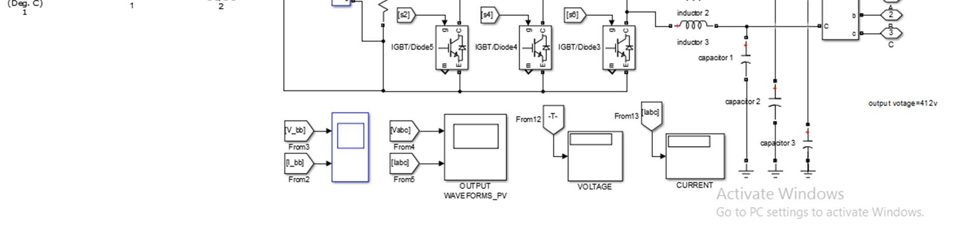
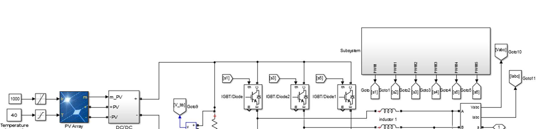
IV. SIMULATION IMPLEMENTATION
In this article, the proposed control scheme used MPPT to control the DC voltage of a three level (NPC) inverter connected to the hybrid (PV-battery) system integrated into the grid. It is evaluated using MATLAB/Simulink software under variable load conditions. The amount of power generated/supplied by the PV array depends on the solar irradiation G = 1000 W/m2 and temperature T = 293 K. The proposed system is operated in three possible operating modes depending on the variable load. Simulation blocks diagram representation as shown in Fig 11.