https://doi.org/10.22214/ijraset.2023.49233

11 II
February 2023
ISSN: 2321-9653; IC Value: 45.98; SJ Impact Factor: 7.538
Volume 11 Issue II Feb 2023- Available at www.ijraset.com

https://doi.org/10.22214/ijraset.2023.49233
ISSN: 2321-9653; IC Value: 45.98; SJ Impact Factor: 7.538
Volume 11 Issue II Feb 2023- Available at www.ijraset.com

Abstract: As the population grows daily, the amount of excellent, solid ground available for development decreases, necessitating the use of weaker or softer soil for the construction of buildings and other civil engineering projects. The building of structures built on the problematic broad black cotton soil is fraught with difficulties. It has poor geotechnical subgrade features, including swelling and imperviousness. In this study, an attempt is made to improve the different geotechnical characteristics of black cotton soil by mixing it with waste products like river sand, fly ash, and marble dust. These properties include index properties, swelling characteristics, consolidation characteristics, hydraulic conductivity characteristics, and strength characteristics. Due to the best possible use of these waste materials in the enhancement of various aspects of black cotton soil, these techniques therefore minimised the impact of waste materials on the environment. There are many different types of soil stabilisation, but typically, mechanical, and chemical stabilisation procedures are used to accomplish traditional soil stability. Stabilizers are the additives that are used to stabilise substances. For stabilisation, a variety of stabilisers are utilised, including fly ash, bitumen, rice husk, lime, cement, and other chemicals.
When dry, black cotton soils are extremely hard; yet, when wet, they entirely lose their strength. Widespread issues with expansive soils provide a number of difficulties for civil engineers. Numerous techniques are used to enhance the expanding soils' engineering properties. The study's findings are summarised as follows.
By raising the percentage of Terrasil and maintaining the values of rice husk ash and fly ash, which are 10% and 20% respectively, unchanged, the liquid limit percentage lowers by 0% to 0.08% and grows. When Terrasil is changed while leaving the values of rice husk ash and fly ash, which are 10% and 20% respectively, unchanged, the plastic limit percentage falls from 0% to 0.10 percent. When rice husk ash and fly ash are kept at their constant values of 10% and 20%, respectively, the plasticity percentage drops from 0% to 0.04% and then rises to a high of 0.06% at 30.07. The maximum value is reached before the optimal moisture content (OMC) first increases, then declines. achieved after 0.10% addition of Terrasil while maintaining the 10% and 20% values for rice husk ash and fly ash, respectively, and were equivalent to 27.64%. The compressive strength first increases and then decreases, the maximum value obtained was at 0.06% addition of Terrasil keeping constant value of rice husk ash and fly ash, i.e., 10% and 20% respectively, and were equal to 1.69 gm/cm2. The maximum dry density (MDD percentage) first increases up to 0.06% of Terrasil and then decreases.. The greatest value achieved was at 0.06% addition of Terrasil retaining constant value of rice husk ash and fly ash, i.e., 10% and 20% respectively, and were equal to 0.861kg/cm2. The shear strength initially increases and subsequently drops. As Terrasil's percentage rises while the amounts of fly ash and rice husk ash remain constant at 10% and 20%, respectively, the permeability commonly drops.

Keywords: Black Cotton Soil, Nano chemical, Terrasil, Rice husk
When it comes to a building that is constructed on land, the foundation is quite crucial. In order to sustain the entire building, it must be of extremely high quality. The soil quality surrounding the building must be taken into account for this to be possible. One is able to select the stabilising techniques based on the soil quality. The qualities for a better foundation are achieved during the course of this procedure. It's nothing new. Chinese, Romans, and other civilizations have all used this method of soil improvement. It began in India in the late 1970s. For the past 20 years, India has seen a noticeable surge in the construction of amenities. Pavement development is proceeding quickly as part of it. As a result, by raising the CBR value of the subgrades, the density of the pavement layers contributes to a growth that is both manageable and very desirable in our nation. The conversion of locally based dirt into more suitable material would be an economical alternative...
ISSN: 2321-9653; IC Value: 45.98; SJ Impact Factor: 7.538
Volume 11 Issue II Feb 2023- Available at www.ijraset.com
Due to a number of variables, it could be necessary to increase both their strength and durability. Strength of a structure may be increased by replacing the soil or building a structure with the quality of the soil in mind. The quality of the soil currently on the site can also be improved. The latter assisted in the creation of techniques for stabilising soil. When it comes to the number of development events, soil stabilising techniques that employ less expensive locally accessible materials have a major potential to lower the pavement early construction rate. However, they must use such lands that lack desired features like an engineering product. One of the most common applications for soil stabilisation is in the creation of sub-grades and sub-bases during the building of roadways. Over time, a variety of techniques have been employed to preserve soils with strength issues. Stabilization has recently become stronger and is getting better.
It is activity of changing the soil’s residential qualities via methods of mechanical, chemical nature to make it better in every sense of the word. The idea behind it is to make the soil viable for engineering purpose. The betterments can be in the tensile strength, capacity to bear weight and so on. Creation of hydrophobic surfaces can be done to prevent roads etc. from failing. A number of substances can be used for stabilization process like biopolymers, fiber, chlorides of calcium and magnesium etc. Furthermore, new non typical ingredients are also used like copolymer and polymer-based products. The first step and the step that determines the success of the entire process is the testing of the soil. This step forms the basis of our entire process as it helps choose the methods and techniques which will help us achieve the goal. The main principles for the stabilization are as follows:
1) Assessing the various qualities/properties of the soil where the structure needs to be made.
2) Determining the thing that needs to be change in the soil so as to make it better for structure construction and also evaluating how economical can it be.
3) Creation of a sample with the required properties and testing it for the intended values in order to achieve stabilization
The focus when construction is done is to achieve a strong structure that will stand the test of time. Thus, stabilization of soil is of importance for the structures to stand. If at some place soil isn’t feasible for construction replacing it can be quite expensive hence soil stabilization is the best alternative. The advantages are:
Workability increases.
Durability increases.
Strength can be increased.
Cost efficiency.
Energy efficiency.
More efficient structures.
Mechanical Method Overstabilization: Soils of varying gradations are mixed together in this treatment to acquire the desired residential or commercial soil property.
Additive Method: Means adding manmade products to the soil, which enhances the quality of the soil in the right quantities. It is possible to use materials such as cement, lime, bitumen, fly ash, and so on. Two methods of oriented and random fiber reinforcement can be performed.
Black cotton soil also goes by the names swelling soil or shrink soil. This is due to its capacity to change as per the moisture content. These soils are best when it comes to the purpose of cultivation, however the same cannot be said for construction. Because of the changes to it due to moisture content it may result in damage to the structure built on it which can be so extreme at times that it may collapse. This soil type is dominant in the southern part of the country like states of Maharashtra, MP, Andhra Pradesh to name a few. They are also found around the river valleys in these regions. These soils are rich in minerals thereby making them highly fertile and having property of water retention the s soils tend to be best suited for cultivation of fruits and vegetables, cereals, cotton etc.
ISSN: 2321-9653; IC Value: 45.98; SJ Impact Factor: 7.538
Volume 11 Issue II Feb 2023- Available at www.ijraset.com
The river valleys of the south i.e., of the rivers Tapi, Narmada Godawari, Krishna the depth of this soil is huge. To make this soil fit for the purpose of construction thus, measures need to be taken. Complete change of soil in a region before building is an option but it is very expensive as already mentioned. Hence, alternative has been explored in this dissertation.
1) The main objective of the present work is to study is to enhance the properties of Soils.
2) To study the effects of Terrasil and on a constant ratio of fly ash and rice husk ash on the index properties of expansive soils.
3) To study the effects of Terrasil and on a constant ratio of fly ash and rice husk ash on the engineering properties of expansive soils.
4) Feasibility of Terrasil, fly ash and rice husk ash as a stabilizer in expansive soils.
5) Increasing the bonding between grains, thus increasing the mechanical strength.
6) Filling the voids that cannot be eliminated.
7) To utilize industrial as well as agricultural waste products in the process of road construction.
Praveen Patel and Dr. H.K. Mahiyar(2014)experimentally examined the effect of stabilization on soil utilizing rice husk ash , lime and fly ash . They noticed that on adding lime, liquid limitation and plastic limit reduces whereas on including fly ash and rice husk, both increases. CBR value increases when content of rice husk and fly ash boosts. Best amount of the additives was found to be 20% and that of lime limited to 8%. UCS worth increases with the increase in percentages. On developing roadway treated with above percentages of numerous admixtures, a 60% decrease in density of sub-base layer, and 40.7% reduction in DBM. Prabhakar et al. (2020) presented an idea of adding dust from quarries and sand from foundry for the purpose of stabilization of soil to it. Need being increasing the weight bearing quality. Standard tests were carried out on each. Then the percentages of the additives were altered in percentage and each of the samples create were tested for various properties and a comparison was made. It was seen that best results were achieved at 15% presence of both the aforementioned additives.
This chapter describes the research methodology used to analyse the engineering properties of black cotton soil of traditional & at a different dose (0%, 0.02%, 0.04%, 0.06%, 0.08% and 0.10%) of Terrasil, RHA of 10% and FA of 20% to meet this goal. During the investigation the following tests are carried out.
1) The consistency limits
a) Liquid
b) Plastic
c) Plasticity index
2) Specific gravity Test
3) Standard Proctor Compaction Test
4) Unconfined Compressive Strength Test
5) Shear Strength Test
6) Permeability Test
A. Consistency Limits
The tests for limits of Liquid, Plastic and Plasticity index are given below:
1) Determination of Limit of Liquid
This limit of liquid of soil is the point at which it starts to behave like liquid. Tests, 3-4 in number are carried out. No. of blows N in each test is figured out and results are plotted. The list of equipment used to carry out these tests are listed below.
a) Apparatus Used
Arthur Casagrande’s apparatus liquid limit device
Grooving tools
Oven
Evaporating dish / glass sheet
ISSN: 2321-9653; IC Value: 45.98; SJ Impact Factor: 7.538
Volume 11 Issue II Feb 2023- Available at www.ijraset.com
Spatula
425µ ISisieve
Weighing3balance, 3precisioni0.01gm
Washbottle
b) Procedure
Ist the drip of the mug is adjusted which needs to be 1 cm at p.o.c at base.
120 gm. of sample is taken and passed 425μsieve.

Water is added to the sample and blended for a maximum of 30 mins and a minimum of 15 mins. A consistent mixture is achieved.
Then the mixture is placed in amp conditions for quite some time.
A portion of this sample is then taken and remixed. It is then to be put in the cup to have a max depth of 1cm.
Next is to cut a groove in the sample.
The device handle is then turned at 2rps. Blows are to be counted till 2 halves of sample are achieved due to stream.
The next step is collecting of sample and placing in an airtight container and determination of water content.
The soil left from the sample needs to be added to the portion that was left earlier.
Water content is then changed by either addition of water or soil is kneaded.
Steps 4 to 10 are reperformed and N is determined. A curve is plotted between N & w.
The limit of liquid is then identified corresponding to N = 25.

This limit is basically the point at which the soil starts to crumble when 3mm dia threads are rolled.
Equipment Used
a) Porcelain cup (dia = 120mm) or glass plate (450 mm & 10 mm)
b) The ground glass plate about200 mm x 150 mm.
c) The Metallic rod 3 mm dia. and 100 mm long.
d) The oven .
e) The spatula.
f) The moisture content can.
Practice
30 gm. of sample is taken and passed 425μsieve.
Water (distilled) is added to the sample and blended. A consistent mixture is achieved enough to form a ball.
Then the mixture allowed to rest for quite some time.
8 gm of this sample is taken and rolled 80 – 90 strokes p.m. on the plate to form 3 mm dia threads.
ISSN: 2321-9653; IC Value: 45.98; SJ Impact Factor: 7.538
Volume 11 Issue II Feb 2023- Available at www.ijraset.com
Lesser than 3 mm dia means presence of more water. Kneading the sample more is what needs to be done if this is the case.
This process is repeated till crumbling takes place.
Crumbled soil needs to be collected and placed in an air- tight container.
Repeat the steps for a couple of more samples.
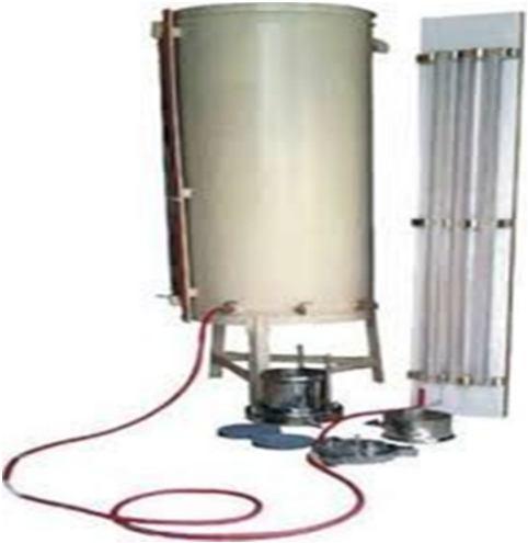
B. Determination of Permeability
The device used for this measurement is a permeameter. The coefficient being:
K= log cm/sec
C. Equipment Used
1) Permeameter mould, internal size= 100mm, effective height =127.3 mm, capability= 1000 ml.
2) Collar 100 mmdia& 60 mm height.
3) Plate
4) Base
5) Cape
6) Compaction Equipment
7) Water supply
8) Vacuum Pump
9) Collection chamber 10) Stopwatch
11) Funnel
12) The thermometer
13) The weighting balance with accuracy 0.1 gm
14) The filter papers
15) The graduated glass standpipe, 50 to 200 mm diameter.
16) The Supporting frame for the standpipe and the clamp.
D. Practice
1) Get rid of collar. Measure the dimensions and weigh it.
2) Apply a little grease on the inside to the mould.
3) Fix the mould in base and collar.
4) 2.5 g. of sample is taken.
5) Remove the collar and base plate
6) A small portion from sample is taken to find water content.
7) Saturate the porous discs (stones)
8) Place a porous disc on a drain base and keep a filter paper on a porous disc.
9) Put the mould with soil on base of the drain, after introducing a washer in between
10) Hygiene mould based edges and applies grease in the grooves surround them.
11) Finally put a filter paper, porous disc and connect the drain cap using washer.
ISSN: 2321-9653; IC Value: 45.98; SJ Impact Factor: 7.538
Volume 11 Issue II Feb 2023- Available at www.ijraset.com
12) At the base now connect the water tank to the exit and allows water to move up hill as long as the sample is saturated. On the sample top the free water gather for a depth of about 100 mm. Alternatively by subjecting the specimen to a steadily rising vacuum with the bottom exist closed, the soil of low permeability can be filled to extract air from the voids. Slowly raise the vacuum to 7000 mm of mercury and depend on the soil form to manage it for 15 min. or more. Close both the outlet after sample is filled.
13) With the anticipated water the empty portion of the mould is filled with no effect on soil.
14) At end remove the tank from the exist.
15) Put water in standpipe
16) By removal of stop cock allow the water to remove all air in the mould.
17) Reinsert the cock.
18) Select h1 and h2. Calculate? h1h2.
19) This step involves fall from h1 to h1 h2 and from that to h2.
20) Replication of the 19 step at least two times, after altering the h1 and h2.
21) Halt the water flow and parts need to be detached.
22) For the water content determination take now a small amount of the soil specimen.
The strength of unconfined compressive is given as:
Equipment Used
1) Unconfined compression apparatus
2) Proving ring
3) Dial gauge
4) Balance
5) Oven where A= A0
1– ɛ
6) Stopwatch
7) Sampling tube
8) Mould
9) Sample extractor
10) Knife
11) Vernier caliper
Practice
Figure.4: Apparatus for Unconfined Compressive Strength and Shear Strength

Prepare the soil specimen at the desired water content and density in the large mould.
Push the sampling tube into the big mould, and remove the sampling tube filled with soil. For undisturbed sample, push the sampling tube into the clay sample.
Saturate the soil sample in the sampling tube by an ideal method
Coat the split mould gently with a thin layer of grease. Weigh the mould.
Extrude the sample out of the tasting tube into the splitting mould; utilize the sampling e tractor and the knife.
Cut the two ends of the specimen in the split mould and weigh the mould with the specimen.
Get rid of the specimen from the split mould by splitting the mould into 2 parts
ISSN: 2321-9653; IC Value: 45.98; SJ Impact Factor: 7.538
Volume 11 Issue II Feb 2023- Available at www.ijraset.com
Determine the length and size of the specimen with Vernier callipers.
Place the specimen on the bottom plate of the compression device, change the upper plat e to make contact with the specimen
Change the dial gauge and providing ring gauge to zero.
Apply the compression load to cause an axial strain at the rate ofi1/2 to 2% per minute.
Record the dial gauge reading, and the offering ring reading everythirty seconds up to a stress ofi6%. The reading may be taken after every 60 seconds for stress in between 6% to 12% and every 2 minutes oriso beyond 12%
Continue the test till failure surface have plainly established or up until an axial strain of 20% is reached.
Procedure the angle in between the failure surface areas and the horizontal, if possible.
Take the sample for the failure zone of the specimen for the water material decision.
F. Standard Proctor Compaction Test
Compaction simply means to decrease air in the soil and make it dense. It shows the dryness in soil. Between the dry density and water material a curve is strained to obtain the max dry density & the optimum water content. M represents total mass, V represents the volume of soil & w represents the water content
1) Apparatus Used
Figure 5: Standard Proctor Compaction Test Apparatus.
a) The 1000ml capacity-based compaction mould
b) Rammer mass 2.6 kg
c) Detachable base plate
d) Collar, 60 mm high
e) 4.75 mmIS sieve
f) Oven
g) Desiccator
h) Weighing balance with 1 gm accuracy.
i) Large mixing pan
j) Straight edge
k) Spatula
l) Graduated jar
m) Mixing tools, spoons, trowels etc

2) Practice
a) Take about 20 kg of air-dried soil. Sieve it through 20mm and 4.75 IS sieves.
b) Determine the percentage kept on 20mm screen, and 4.75 mm screen and the portion pas sing 4.75 mm sieve.do not use the oil retained on 20mm sieve.
c) Figure out the ratio of portion kept and that passing 4.75 mm screen.
d) If portion retained on 4.75 mm sieve is greater than 20, utilize the large mould ofi150m m diameter.
e) If it is less than 20%, the basic mould ofi100mm size can be utilized. The following procedure is for standard mould.
f) Mix the soil retained on 4.75 mm screen and the passing 4.75 mm screen in the proportions determined in step 2 to obtain about 16 to 18 kg of soil specimen.
g) Clean and dry the mould and the base plate to the closest 1 gm.
ISSN: 2321-9653; IC Value: 45.98; SJ Impact Factor: 7.538
Volume 11 Issue II Feb 2023- Available at www.ijraset.com
h) Take about 16 to 18 kg of soil specimen. Include water to it to bring the water c material to about 4% if the soil is sandy and to about 8% of the soil is clayey. Keep the soil in an airtight container for about 18 to 20 hours for maturing. Mix the fully grown soil completely. Divide the processed soil into 6 to 8 parts
i) Attach the collar to the mould. Place the mould on a strong base.
j) Take about 21/2 kg of the processed soil, and position it in the mould in 3 layers.
k) Take about one third the amount first, and compact it by providing 25 blows of the ram mer. The blows need to be uniformly dispersed over the surface area of each layer. The t op of the very first layer should be scratched with a spatula before positioning the 2nd layer. The 2nd layer must likewise be compacted by 25 blows of rammer. Similarly, position on the 3rdilayer and compact it. The amount of soil used must be just sufficient to fill the mould and leaving about 5mm above the top of the mould to be struck off when the collar is gotten rid of.
l) Get rid of the collar and cut off the excess soil forecasting above the mould using a straight edge. Clean the base plate and the mould from outside. Weigh it to the nearest gm
m) Eliminate the soil from the mould. The soil might also be ejected out. Take the soil sample for the water material decision from the top, middle and bottom parts.
n) Add about 3% of water to a fresh part of the processed soil and repeat the Steps 10 to 1 4.
1) Liquid Limit And Plastic Limit At 0% Of Terrasil,0% RHA And 0% FA

The Conventional sample of expensive soil on index-based properties [ Liquid limit & Plastic limit] of examining soils has been shown in the following figure and table
Table No. .1 –Liquid Limit and Plastic Limit for Conventional Sample
ISSN: 2321-9653; IC Value: 45.98; SJ Impact Factor: 7.538
Volume 11 Issue II Feb 2023- Available at www.ijraset.com
Terrasil,
The effect of Terrasil at 0.02%,10% RHA and 20% FA dosage on index properties (Liquid limit& Plastic limit) of examining soils has been shown in Table .2.
Table No. 2 Liquid Limit & Plastic Limit at 0.02% of Terrasil, 10% RHA and 20% FA
Figure No.: 7 Liquid Limits at 0.06% of Terrasil ,10% RHA and 20% FA Hence: Liquid Limit = 56.42%, Plastic Limit = 26.35 Liquid Limit and Plastic Limit at 0.08% of Terrasil ,10% RHA and 20% FA The effect of 0.08% of Terrasil,10% RHA and 20% FA dosage on index properties (Liquid limit and Plastic limit) of examining soils has been shown in table .5.
ISSN: 2321-9653; IC Value: 45.98; SJ Impact Factor: 7.538
Volume 11 Issue II Feb 2023- Available at www.ijraset.com
Figure No.: 8 Liquid Limits at 0.08% of Terrasil ,10% RHA and 20% FA Hence: Liquid Limit = 53.83%, Plastic Limit = 25.95
3) Liquid Limit and Plastic Limit at 0.10% of Terrasil,10% RHA and 20% FA
The effect of 0.10% of Terrasil,10% RHA and 20% FA dosage on index properties (Liquid limit and Plastic limit) of examining soils has been shown in Table .6.
Table No.: .6 Liquid Limit and Plastic Limit at 0.10% of Terrasil ,10% RHA and 20% FA
ISSN: 2321-9653; IC Value: 45.98; SJ Impact Factor: 7.538
Volume 11 Issue II Feb 2023- Available at www.ijraset.com
Figure No.: 9 Liquid Limits at 0.10% of Terrasil ,10% RHA and 20% FA Hence: Liquid Limit = 54.88%, Plastic Limit = 25.60

The consequence of Terrasil at diverse quantity on index properties (Liquid limit, Plastic limit & Plasticity index) of examining soils has been shown in Table 7 Table No.: 7 Liquid Limit, Plastic Limit and plasticity index at usual and numerous %ageof Terrasil
The soil specific gravity is described as the unit weight of the soil mass divided by the unit weight of distilled water at 4°C. It is sometimes required to compare the density of the soil solids to the density of water. This comparison is in the form of ratio and is termed as the specific gravity of the soil. The specific gravity of soil (IS: 2720 part- 2).
Wt. of pycnometer W1 = 573 gm.
Wt. of pycnometer + soil sample W2 = 1073 gm.
Wt. of pycnometer + soil sample + water W3 = 1832 gm. Wt. of pycnometer + water W4 = 1530 gm.
Specificgravityofsoil G= W2–W1 (W4–W1)–(W3–W3)
Hence: Remarks
ISSN: 2321-9653; IC Value: 45.98; SJ Impact Factor: 7.538
Volume 11 Issue II Feb 2023- Available at www.ijraset.com
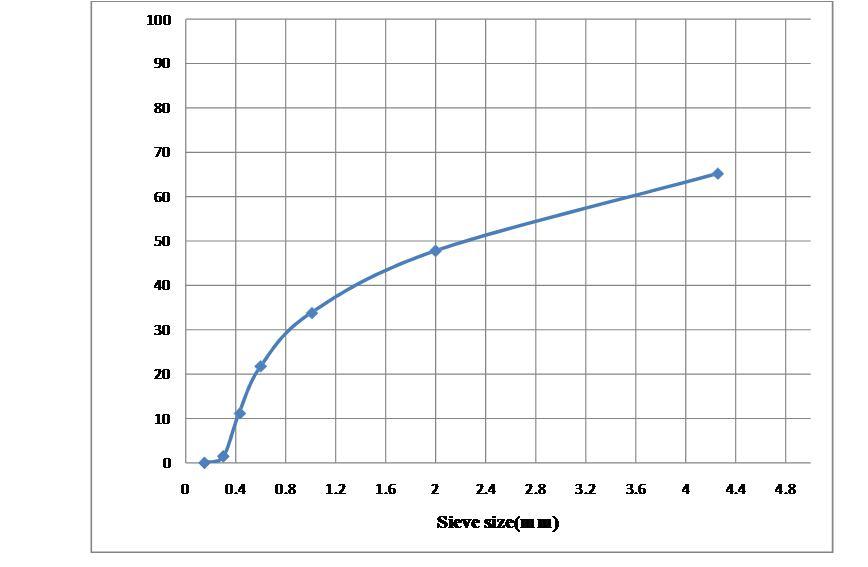
D10 = size at 10% finer by weight =0.45mm
D30 = size at 30% finer by weight =0.91mm
D60 = size at 60% finer by weight =3.56mm
The investigation while conducting this test is described in Table .9.
ISSN: 2321-9653; IC Value: 45.98; SJ Impact Factor: 7.538
Volume 11 Issue II Feb 2023- Available at www.ijraset.com
Result: Max dry density ( ρd) = 1.47 gm/cm3& Optimum moisture content = 21.85%

1) Standard Proctor Compaction Test Of Sample With 0.02% Terrasil, 10% RHA And 20% FA
The effect of 0.02% Terrasil, 10% RHA and 20% FA quantity on Standard proctor compaction test of sample of examining soils has been shown in Table .10
Table no. .10 Standard proctor compaction test of sample with 0.02% Terrasil, 10% RHA and 20% FA
ISSN: 2321-9653; IC Value: 45.98; SJ Impact Factor: 7.538
Volume 11 Issue II Feb 2023- Available at www.ijraset.com
Result: Max dry density ( ρd) = 1.53 gm./cm3& Optimum moisture content = 23.6%
2) Standard Proctor Compaction Test Of Sample With 0.04% Terrasil, 10% RHA AND 20% FA: The effect of 0.04% Terrasil, 10% RHA and 20% FA amount on Standard proctor compaction test of sample of examining soils has been shown in Table .11.
Table 11 Standard proctor compaction test of sample with 0.04% Terrasil, 10% RHA and 20% FA
Figure No. 13 Standard proctor compaction test of sample with 0.04% Terrasil, 10% RHA and 20% FA Result: Max dry density ( ρd) = 1.65 gm./cm3& Optimum moisture content = 22.42%
3) Tandard Proctors Compaction Test Of Sample With 0.06% Terrasil, 10% RHA AND 20% FA : The effect of 0.06% Terrasil, 10% RHA and 20% FA quantity on Standard proctor compaction test of sample of examining soils has been shown in Table .12.
Table No. .12 Standard proctors compaction test of sample with 0.06% Terrasil, 10% RHA and 20% FA
ISSN: 2321-9653; IC Value: 45.98; SJ Impact Factor: 7.538
Volume 11 Issue II Feb 2023- Available at www.ijraset.com
Figure No. 14 Standard proctor compaction test of sample with 0.06% Terrasil, 10% RHA and 20% FA
Result: Max dry density ( ρd) = 1.69 gm/cm3& Optimum moisture content = 23.13%
4) 5STANDARD PROCTOR COMPACTION TEST OF SAMPLE WITH 0.08% TERRASIL, 10% RHA AND 20% FA
The effect of 0.02% Terrasil, 10% RHA and 20% FA amount on Standard proctor compaction test of sample of examining soils has been shown in Table 13.
Table 13 Standard proctor’s compaction test of sample with 0.08% Terrasil, 10% RHA and 20% FA
ISSN: 2321-9653; IC Value: 45.98; SJ Impact Factor: 7.538
Volume 11 Issue II Feb 2023- Available at www.ijraset.com
Result: Max dry density ( ρd) = 1.61 gm./cm3& Optimum moisture content = 25.9%
5) 5standard Proctors Compaction Test Of Sample With 0.10% Terrasil, 10% RHA AND 20% FA:
The effect of 0.10% Terrasil, 10% RHA and 20% FA dose on Standard proctor compaction test of sample of examining soils has been shown in Table .14.
Table no.: .14 Standard proctor compaction test of sample with 0.10% Terrasil, 10% RHA and 20% FA Test

The variable head Permeameter is used to measure the permeability of relatively less previous soils. The coefficient of permeability is given by
K=. log cm/sec
Where h1 = initial head: h2 = final head; t = time interval; a = cross sectional area of the standpipe; A =cross sectional area of the specimen, L = length of specimen.
ISSN: 2321-9653; IC Value: 45.98; SJ Impact Factor: 7.538
Volume 11 Issue II Feb 2023- Available at www.ijraset.com
Here the Length of specimen 12 cm, Diameter of specimen 10 cm , Area of specimen A = 78.5 cm2, Diameter of stand pipe = 1 cm and Area of stand pipe a= 0.785 cm2 Table 15: Coefficient of Permeability
F. Summary Of Various Test Results At Different %Age Of Terrasil
Table 16: Various test results at different %age of Terrasil
Following are the conclusions drawn from the numerous tests that were conducted experimentally while adding Terrasil, maintaining the two additives' levels constant at 10% and 20%, respectively.
1) By raising the proportion of Terrasil, the liquid limit percentage rises from 0.08% to 0.08%.
2) Depending on the amount of Terrasil, the plastic limit percentage drops from 0% to 0.10%.
3) The plasticity percentage rises from 0.04% to 0.06%, with the maximum value being 30.07 at 0.06%.
4) The OMC shows an early increase and a subsequent reduction, with the maximum value being recorded at 27.64% at 0.10% additive.
5) Terrasil's maximum dry density (MDD percentage) predominantly increases up to 0.06% before declining. The highest result, 1.69 gm/cm2, was attained at a Terrasil addition of 0.06%.
6) The compressive strength increases initially before declining; the highest value was attained after a Terrasil addition of 0.06%, which was equivalent to 1.772 kg/cm2.
7) Shear strength was 0.861 kg/cm2 when chemical additive was used at a level of 0.06%. There were rises at initially, followed by declines 8. With an increase in Terrasil content, the permeability typically falls.
To create the finest stabilising mixture possible, fly ash and rice husk ash can be combined with another addition, such as lime, murrum, cement, and other similar materials, and their quantities can be changed.
ISSN: 2321-9653; IC Value: 45.98; SJ Impact Factor: 7.538
Volume 11 Issue II Feb 2023- Available at www.ijraset.com
[1] Amarjit Singh (1967). Use of lime-fly ash in soil stabilisation for roads, Jl. Of Indian Roads Congress, vol-XXX-1,143.
[2] Amos,D.F. and Wright,J.D.,1972, The effect of soil fly Ash on soil physical characteristics, Proc. Of Third Mineral Waste Utilisation Symposium, Chicago, pp. 95- 104.
[3] Bell, F.G., 1993, Engineering treatment of soils, E & FN Spon Publishers, London.
[4] Bhoominathan,A. and Hari,S.,1999, Behaviour of fly ash under static and cyclic loading, Proc.of Indian Geotechnical Conference, Calcutta,pp.324-326.
[5] Bose, B. (2012), “Geo-engineering Properties of Expansive Soil Stabilized with Fly Ash”, Electronic Journal of Geotechnical Engineering, Vol. 17, pp. 13391353.
[6] Cokca, E. (2001), “Use of Class C fly ash for the stabilization of an expansive soil”, ASCE Journal of Geotechnical and Geoenvironmental Engineering. Vol. 127, Issue 7, pp. 568–573.
[7] Cokca,E.,2001, Use of class-C fly ashes for the stabilisation of expansive soil, Jl.of Geotechnical and Geo environmental engg.,vol.127,pp.568-573.
[8] Gayathri, M., P. Singh, and M. Prashanth, Soil Stabilization using Terrasil, Cement and Flyash. i-Manager's Journal on Civil Engineering, 2016. 6(4): p. 31.
[9] Hakari, U.D.and Puranik,S.C.,2010,Evaluation of swell potential and identification of expansive and problematic soils in civil engineering works by newly developed matrices based on index and grain size properties, Electronic Journal of Geotechnical Engineering (EJGE),vol.15,pp.1712-1726.
[10] Holtz, W. G., and Gibbs, H. J. (1956), “Engineering properties of expansive clays” Transactions ASCE. Vol. 121, pp. 641–677.
[11] Indraratna,B.,Nutalaya, P. and Kuganenthria, N.,1991, Stabilisation of a dispersive soil by blending with fly ash, Qtrly Jl. of Engineering Geology, vol.24,pp.275-290.
[12] Johnson, R. and K. Rangaswamy. Improvement of Soil Properties as a Road Base Material Using Nano Chemical Solution. in 50th Indian Geotechnical Conference. 2015.
[13] Kumar, A., Walia, B.S., and Bajaj, A. (2007), “Influence of Fly Ash, Lime and Polyester Fibers on Compaction and Strength Properties of Expansive Soil”, Journal of Materials in Civil Engineering, Vol. 19, Issue 3, pp. 242-248
[14] Lekha, B., S. Goutham, and A.R. Shankar. Laboratory investigation of soil stabilized with nano chemical. in Proceedings of Indian Geotechnical Conference. India December. 2013.