ISSN: 2321 9653; IC Value: 45.98; SJ Impact Factor: 7.538

Volume 10 Issue X Oct 2022 Available at www.ijraset.com


ISSN: 2321 9653; IC Value: 45.98; SJ Impact Factor: 7.538

Volume 10 Issue X Oct 2022 Available at www.ijraset.com
1
3
Abstract: Cranial implants are utilised during the medical surgery known as cranioplasty to fill the deficiency and preserve the cranium's aesthetic, which eventually aids in fulfilling the patients' metabolic demands. There are several materials, each with unique benefits and drawbacks categorised into biological and synthetic material. The research of various structures that may be used in biomedical implants to replicate the structure or qualities of bone has been facilitated by the development of specific materials throughout history and improvements in manufacturing processes. One of the cellular structure types that is frequently utilised in biomedical implants is the lattice structure. This work models a cranial implant based on lattice structures. Body centered cubic (BCC), Face centered cubic (FCC), and fluorite were the three lattice structures that were selected. The effects of external load on cranial implants are next examined while considering two polymeric materials, Polymethylmethacrylate (PMMA) and Polyetheretherketone (PEEK).
Keywords: Cranioplasty, Cranial Implants, Cellular structure, FEA analysis, PEEK, PMMA
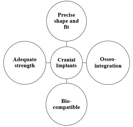
The brain, one of the body's most complex organs, controls and governs most physical processes, including motor coordination, memory, the operation of other organs, etc. It is surrounded by eight cranial bones that are connected by sutures. When the cranial bones become abnormal due to certain conditions like brain tumours, infections, or accidents, a surgical procedure called a craniectomy is performed. This procedure is also referred to as the primary surgery in cases of tumours or aneurysms. When restoring broken bones after an accident is not possible, cranial implants are utilised to repair the gap and protect the brain [1]. This surgical process is called cranioplasty. Major function for performing cranioplasty is to maintain the metabolic demands, intracranial pressure, control the alteration in cerebral spinal fluid, reducing the risk of trephined syndrome and sinking flap [2]. There are different types of cranial implants of different types of materials are used during the history. Each material has its advantages and disadvantages in terms of usage, manufacturability, cost, bone integration etc. Implants are basically divided into two categories i.e., Biological and Synthetic Implants. Biological implants are those in the implants is made from the bones of host or any other host or animal parts. Earlier these implants are used but there is lot of issue in terms of infection, immune response, and collection of bones but still the autografts are done in which the bone is harvested from the host and implanted on the site. Synthetic implants are used as they are less prone to infection and due to their acceptable properties of different materials, they became prominent. Aluminium was the first metal to be used as a cranial implant. Synthetic implants are further divided in terms of material i.e., metal, polymer, Ceramic [3] An ideal cranial implant (Fig.1) material should possess properties such as, ideal fit as per defect size, radiolucent, better bone acceptance, non reactive, chemically stable, cost effective, easy to manufacture. Till this time the researchers are working on different type of materials but still there is no ideal material. Most favourable material used in market are Titanium alloys, Polymethyl Methacrylate (PMMA), Polyetheretherketone (PEEK) [4]
Fig. 1 Properties of cranial implants

ISSN: 2321 9653; IC Value: 45.98; SJ Impact Factor: 7.538 Volume 10 Issue X Oct 2022 Available at www.ijraset.com

Earlier the implants are manufactured by using the traditional methods such as casting, forging, machining etc. In recent times the advancement in the technology and certain drawbacks in the traditional methods has led to the minimal usage of these old techniques. With the use of additive manufacturing technology in manufacturing of biomedical implants the researchers started working on the different types of cellular structures which were very complex in manufacturing but became easy with this technology [5]. The concept of cellular structures was introduced by Gibson and Ashby Evans. They considered foams, honeycombs, and lattice structures. Open and closed cell foams are the two forms of foam. In foams, the unit cell form and cell wall orientation are created at random space. Due to the arrangement of identical cell shapes, honeycomb structures have uniform size, shape, and geometry. Numerous alternative cell shapes exist, including tetrahedrons, hexachiral, and tetrachiral. Auxetic structures are now being researched and developed, which has enhanced their functionality and broadened their range of applications. Lattice structures are essentially a subset of cellular structures in which the arrangement of the unit cell is irregular or periodic. These have more design freedom than foams and honeycomb structures, making them superior. It may be customised to meet needs and improve mechanical performance while maintaining a specific porosity level [6,7]. Bungo Otsuki (2006) and colleagues produced several titanium dental scaffolds with variable pore diameters and complicated 3D structures, implanted them on rabbit femoral condyles, and monitored them over six to twelve weeks. The relationship between bone development and porosity was better understood thanks to this study [8]. Lattice structure possess properties such as high specific stiffness and strength, high energy absorption, high surface area, lightweight, porous. Mostly lattice structures are currently used in orthopaedic implants which has provided satisfactory results [9]. This research paper aim is to model and analyse the performance of lattice structure based cranial implants. Different type of lattice structures unit cell was considered for this study shown in Fig 2, Body centred cubic (BCC), Face centred cubic (FCC) and Fluorite. The von Mises stress and deformation produced in the implant with PEEK and PMMA material properties under the effect of load is studied.
Fig. 2 Unit cell of Lattice structures

Firstly, a solid CAD model of an implant is made in shape of elliptical dome to mimic the curvature of cranial bones. A medium sized cranial implant [10] is developed using Solidworks 2021 student edition of dimensions (120X75X8) mm and implant thickness is considered 1.5 mm [11]
Fig. 3 Solid Implant model

ISSN: 2321 9653; IC Value: 45.98; SJ Impact Factor: 7.538 Volume 10 Issue X Oct 2022 Available at www.ijraset.com

After the solid CAD file is modelled, the file is then transferred into nTopology software and a workflow is generated for the generation of selected lattice structure. Considered beam thickness is 0.75mm, it is the diameter of every strut present in unit cell. Final sample design outcomes are shown in Fig. 4.

For the analysis polymer based material is considered, Polymethylmethacrylate (PMMA) and Polyetheretherketone (PEEK). PMMA is considered as this material is cost effective and properties are kind of like bone. A study was conducted by Gary J Huang in which 20 patients received 22 PMMA implants. During a 2 year period, the patient was regularly checked and analysed and it was found that there were no cases for infections in anyone or leakage of CSF due to poor fit. Only 2 major and 1 minor complication was noted [12] PEEK material is considered for cranial implants as it has high strength, stiffness, durability, chemically inert but it is not cost effective as PMMA. The complications rate of PMMA and PEEK are mostly similar [13]. The properties of materials considered during analysis is shown in Table 1 Assumption is taken that both materials are isotropic in nature [14]
Table 1. Properties of selected materials
Physical property PEEK PMMA Youngs Modulus (MPa) 4000 3000 Poisson's ratio 0.4 0.38
Density (kg/mm3) 1360 X 10 9 1180 X 10 9 Yield Strength (MPa) 95 83
This type of study is conducted when experimental solutions are not possible due to the complex geometry. This type of tools helps us in understanding the design whether it will be feasible or not before developing. For conducting the analysis, nTopology software is used as the lattice structures have very sharp and intricate features and this tool is basically developed for the development and study of these structures. Meshing of these structures in any other FEA tool requires high computation power and time while in this tool there is a dedicated block for meshing of these type of structures which basically converts the and divides the numbers of struts into basic 1D elements as per the element size. Load considered was 400N [15] on the top surface area of implant and the outer border which is fixed to the bone with different types of methods is considered fixed as shown if Fig. 5.
Fig. 5 Boundary conditions

ISSN: 2321 9653; IC Value: 45.98; SJ Impact Factor: 7.538 Volume 10 Issue X Oct 2022 Available at www.ijraset.com
Total three numbers of cranial implants were modelled. All the modelled lattice based cranial implants are studied with two different materials under the same load and boundary conditions. The von Mises stress values and deformation values are shown in Table 2 and 3 respectively.
Table 2. von Mises stress results Unit cell PEEK PMMA von Mises stress (MPa)
BCC 22.1 23.21 FCC 22.14 22.34 Fluorite 16.81 16.93
Table 3. Deformation results Unit cell PEEK PMMA Deformation (mm)
BCC 0.45 0.6 FCC 0.273 0.364 Fluorite 0.179 0.238
From table 1 and 2, PEEK material shows lesser generated stress and deformation values in comparison to PMMA. Minimum stress and deformation are generated by Fluorite structure. The results obtained after the analysis are satisfactory as the stress values generated by all structures are under the yield strength of both materials means it is safer to use and the deformation values are also so minimum that will be absorbed by the cerebral spinal fluid which is between the cranium and the brain in which it floats without causing any harm to the brain. Graphical representation of results is shown in Fig. 6.

Fig. 6 von Mises stress and deformation values for both materials
The fluorite unit cell structure exhibits low stress values and deformation, according to the study that was done. The computed stress levels for PEEK and PMMA only slightly differ from one another. When it came to overall deformation, PEEK material performed better. The produced stress levels fell short of the yield strength value, demonstrating the safety of implants by preventing plastic deformation and ideally, they regain their initial position. Both polymer materials can be utilised in place of metallic components like titanium since they are both reasonably priced and provide enough brain protection. The cranial implants are made porous, light weight, and with strong structural integrity by integrating these structures into them. Integrating lattice elements with cranial implants can provide a different approach to creating implants that are more successful and comfortable for patients.
The authors would like to express their gratitude to nTopology team for providing the educational license for the research work.

ISSN: 2321 9653; IC Value: 45.98; SJ Impact Factor: 7.538 Volume 10 Issue X Oct 2022 Available at www.ijraset.com
[1] Basel A. Khader, Mark R. Towler. Materials and techniques used in cranioplasty fixation: review. Materials Science and Engineering C66, 315 322, 2016.
[2] Alkhaibary A, Alharbi A, Alnefaie N, Oqalaa Almubarak A, Aloraidi A, Khairy S. Cranioplasty: A Comprehensive Review of the History, Materials, Surgical Aspects, and Complications. World Neurosurgery, 2020.
[3] Shah AM, Jung H, Skirboll S. Materials used in cranioplasty: a history and analysis. Neurosurg Focus, Volume 36(4), 2014.
[4] Aydin, S., Kucukyuruk, B., Abuzayed, B., Aydin, S., & Sanus, G. Z. Cranioplasty: Review of materials and techniques. Journal of neurosciences in rural practice, Volume 2, Issue 2, 2011.
[5] Tobias Maconachie, Martin Leary, Bill Lozanovski, Xuezhe Zhang, Ma Qian, Omar Faruque, Milan Brandt, “SLM lattice structures: Properties, performance, applications and challenges,” Materials & Design, Volume 183, 2019, doi: 10.1016/j.matdes.2019.108137.
[6] Chen Pan, Yafeng Han, Jiping Lu, “Design and Optimization of Lattice Structures: A Review,” Applied Sciences, Volume 10(18):6374, 2020, doi: 10.3390/app10186374.
[7] Y. Tang, G. Dong, Q. Zhou, and Y. F. Zhao, “Lattice Structure Design and Optimization with Additive Manufacturing Constraints,” IEEE Transactions on Automation Science and Engineering, vol. 15, no. 4, pp. 1546 1562, Oct. 2018, doi:10.1109/tase.2017.2685643.
[8] Otsuki B, Takemoto M, Fujibayashi S, Neo M, Kokubo T, Nakamura T, “Pore throat size and connectivity determine bone and tissue ingrowth into porous implants: three dimensional micro CT based structural analyses of porous bioactive titanium implants,” Biomaterials,2006, 27:5892 900, doi: 10.1016/j.biomaterials.2006.08.013.
[9] Park KM, Min KS, Roh YS, “Design Optimization of Lattice Structures under Compression: Study of Unit Cell Types and Cell Arrangements,” Materials (Basel), 2021, doi: 10.3390/ma15010097.
[10] Uygur S, Eryilmaz T, Cukurluoglu O, Ozmen S, Yavuzer R. Management of cranial bone defects: a reconstructive algorithm according to defect size. Journal of Craniofacial Surgery: Volume 24, Issue 5, page no. 1606 1609, 2013.
[11] Moiduddin K, Mian SH, Umer U, Alkhalefah H., “Fabrication and Analysis of a Ti6Al4V Implant for Cranial Restoration”, Applied Sciences, 2019.

[12] Huang GJ, Zhong S, Susarla SM, Swanson EW, Huang J, Gordon CR. Craniofacial reconstruction with poly (methyl methacrylate) customized cranial implants. J Craniofacial Surg. 2015 Jan;26(1):64 70.
[13] Zhang J, Tian W, Chen J, Yu J, Zhang J, Chen J. The application of Polyetheretherketone (PEEK) implants in cranioplasty. Brain Research Bulletin, 2019.
[14] V Phanindra Bogu, Y. Ravi Kumar, Asit Khanra, Modelling and structural analysis of skull/cranial implant: beyond mid line deformities, Acta of Bio Engineering and Biomechanics, 2017.
[15] Jagoda Maciejewska and Hubert Jopek, An Analysis of Auxetic Cranioplasty Implant, Vibrations in Physical Systems, Volume 31, pages 2020315 1 2020315 8, 2020.
