ISSN: 2321-9653; IC Value: 45.98; SJ Impact Factor: 7.538 Volume 10 Issue XII Dec 2022- Available at www.ijraset.com


ISSN: 2321-9653; IC Value: 45.98; SJ Impact Factor: 7.538 Volume 10 Issue XII Dec 2022- Available at www.ijraset.com

Abstract: In this paper the 3D assembly of the universal joint was realized using Autodesk Inventor Professional 2022 and finite element analysis was performed, in order to determine the state of stress and deformation, by applying restrictions and loads conditions. The materials chosen, for assembly parts, was in accordance with the specialized literature. Initially, high Von Mises stress values were obtained, higher than the admissible limits of the chosen materials. After the changes repeated of the cardan fork geometry, mainly of the fillets and chamfers, the Von Mises stress values dropped below the admissible limits of the chosen materials, registering a maximum in the same area as at the beginning of the analysis, at the cardan cross.
Keywords: Universal joint, Solid modeling, Static analysis, Autodesk Inventor
The power transmission system consists of several components, such as the universal joint assembly, differential transmission, etc. The cardan assembly consists of two forged steel yokes (forks) that join the two shafts. Spider hinges are used to connect two yokes together so that the faces of both yokes are at right angles to each other. A universal joint (U-joint) is a joint in a rigid rod that allows the rod to move up and down as it rotates to transmit power by changing the angle between the transmission output shaft and the drive shaft. The most common types of U-joints used in the automotive industry are the hook or cardan joint. A basic U-joint consists of a drive yoke, driven yoke and cross spider. Each link part of the spider are assembled in a needle bearing together with the two yokes [1]. In the transmission system of a motor vehicle, the main transmission shaft, the propeller shaft and the differential pinion shaft are not in one line, and therefore the connection between them is made by the universal coupling. One universal joint is used to connect the main drive shaft and the propeller shaft, other universal joints are used to connect the other end of the propeller shaft and the differential pinion shaft [2]. The universal joint, on the other hand, consists of two forged steel yokes or forks joined to the two shafts being engaged and located at right angles to each other.
S. Kinme et al. [3] offered solutions for the repeated optimization of the shape of the analyzed cardan joint, finally obtaining a shape with high rigidity and with a low cost.
H. Bayrakceken et al. [4] presented spectroscopic analysis, metallographic analysis and hardness measurements performed on the universal joint yoke and a drive shaft of an automotive transmission system. To determine the stress resistance, they used the finite element method analyzing the section where the maximum stresses were recorded.
Farzad Vesali et al. [1] analyzed the dynamics of universal joints and proposed some practical methods to improve their performance. The forces in the joint bearings are calculated using an analytical method that is also supported by numerical modeling. Such models are also used to calculate the magnitude of excess loads on the cardan joint.
S. G. Solanke and A. S. Bharule [5] investigated stress distribution for the optimization of universal joint yoke under variable stress conditions. The yoke is analyzed under the action of torque loads from the steering, observing the stress concentration region.
Naik S. Giridhar et al. [6] analyzed the cardan joint for the demand conditions taken from the specialized literature, the power transmission system being the system that causes the vehicles to move by transferring the torque produced by the engines to the wheels after some modifications.
P. G. Tathe et al. [7] analyzed the failure of a cardan joint of a power transmission of a car. To determine the stress conditions at the damaged section, they used the finite element analysis method, and the validation process was done through physical experimentation. The power transmission system of an automobile consists of several components that sometimes experience failures that lead to damage to the transmission system.
Kamal Kashyap and D. G. Mahto, [8] presented a finite element analysis predicting the behavior of universal joint under different loads. The joint of universal joints (universal coupling) is very important for the transmission of power from one shaft to another. Sometimes deterioration in this assembly occurs due to improper design and analysis
ISSN: 2321-9653; IC Value: 45.98; SJ Impact Factor: 7.538 Volume 10 Issue XII Dec 2022- Available at www.ijraset.com

Ritesh P. Neve [9] analyzed the universal joint by performing certain modifications of the existing geometry and analyzes for identical stresses and boundary conditions. A universal joint is a joint that allows the rod to twist in any direction and is commonly used on shafts that transmit rotary motion. Other researchers analyzed the rigid flange coupling because it is performed similarly to the universal joint. In their work, they used ANSYS software, in the study of the finite element method, for different torque conditions and different loads, and made checks by hand calculation. Studies were also done for the stress resistance limits of the joint yoke, calculated by the analytical method, and then the obtained result was verified by the numerical method. It is shown that small variations in the geometry of the joint yoke lead to a significant reduction in the stress level. The iterative procedure of shape corrections and the repetition of numerical stress calculations were performed to identify the favorable relationship between the geometric parameters of the universal joint yoke.
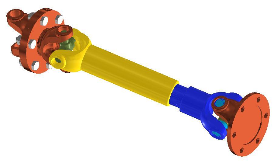
Solid modeling of the all parts of the universal joint and the assembly was done using Autodesk Inventor version 2022. The solid model of the universal joint and drive shaft assembly are shown in Fig. 1


Fig. 1 Universal joint and drive shaft assembly
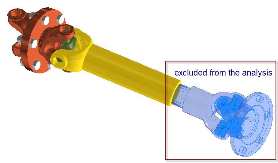
In this study, the cardan assembly was modeled and analyzed using the finite element analysis method using Autodesk Inventor 2022. In order to reduce the system requirements, some of the component parts of the assembly Fig. 2 were excluded from the finite element analysis The static analysis was chosen as the type of analysis
Fig. 2 The parts excluded from the analysis
Regarding the choice of materials, it is specified that some of them were assigned automatically by the software, reference is made here to the materials for the elements that were used from the program library: needle bearing, washers, etc. the others being specified for each individual element. Materials were used in accordance with the data presented in the specialized literature, materials with properties shown in Table 1.
TABLEI
Parameters
Young’s Modulus [MPa] Poisson's Ratio Shear Modulus [MPa]
Stainless Steel Steel Alloy
193000 0.30 86000
205000 0.3 80000
Stainless Steel AISI 304
195000 0.29 86000
Stainless Steel AISI 430
199947 0.29 77220.9
Steel AISI 1020 107 HR
207000 0.33 77820
Parameters
Mass Density [Ns2/mm4]
Tensile Strength [MPa] Yield Strength [MPa] Thermal Expansion Coefficient
Thermal Conductivity N/(sec oC)
Specific Heat mm2/(sec2 oC)
Stainless Steel Steel Alloy
8E-09 540 250 1.04E-05 1.62E+01 4.77E+08
7.73E-09 400 250 1.2E-05 4.5E+01 4.8E+08

ISSN: 2321-9653; IC Value: 45.98; SJ Impact Factor: 7.538 Volume 10 Issue XII Dec 2022- Available at www.ijraset.com
Stainless Steel AISI 304
8E-09 505 215 1.73E-05 1.62E+01 5E+08
Stainless Steel AISI 430
7855E-09 413.683 289.578 1.17E-05 2.49E+01 4.6E+08
Steel AISI 1020 107 HR
7.87E-09 441 260 1.17E-05 5.19E+01 4.86E+08
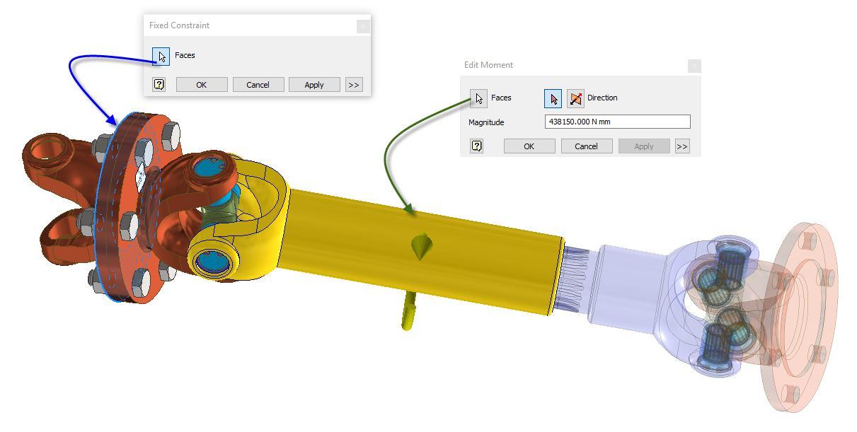
Restrictions have been imposed on the connection flange of the assembly and the maximum moment was applied on the shaft, as show in Fig. 3
The calculation moment, MC, used in the analysis of the state of stresses and deformations of the assembly study, is determined taking into account the hypothesis in which an engine produces the maximum moment MM, in the first gear. The value of the applied moment was 438.15 N·m
This calculation moment is given by the equation: 1cv M c i M M (1) where: MM – maximum moment; icv1 – the transmission ratio of the first gear
Fig. 3 A restrictions and load condition
To generate the mesh, the automatic generation mode was used with parabolic element order, the assembly model being meshed into 200489 elements and 355164 nodes, Fig. 4
Fig. 4 The assembly meshing


ISSN: 2321-9653; IC Value: 45.98; SJ Impact Factor: 7.538 Volume 10 Issue XII Dec 2022- Available at www.ijraset.com

The following figures show the results obtained from the FEM analysis for the assembly. Following the finite element analysis, high values were recorded for the Von Mises stresses of approximately 393 MPa, higher values compared to the material's yield strength of 250 MPa, Fig. 5 The maximum value was recorded at cardan fork model, detail, Fig. 6.

In order to record lower values of the Von Mises stress, successive changes of the cardan fork fillet were made. Following the modifications and successive runs of the FEM analysis of the assembly, the maximum value of the Von Mises stresses decreased to 213.9 MPa, Fig. 7, this time being in accordance with the properties of the analyzed materials. The maximum value was also recorded at one of the cardan fork connections


Fig. 7 Von Mises stress – after changes
The total deformations were also analyzed. The value of the total deformation after the changes made was 0.294 mm, Fig. 8

Fig. 8 Displacement – after changes
The minimum safety factor was 1.15, Fig. 9
Fig. 9 Safety factor – after changes
ISSN: 2321-9653; IC Value: 45.98; SJ Impact Factor: 7.538 Volume 10 Issue XII Dec 2022- Available at www.ijraset.com
The purpose of this work was to carry out a study of the behavior under the action of loads of a cardan transmission. In order to determine the state of stresses and strains, the 3D models of the components of the cardan transmission were made with the help of the Autodesk Inventor Professional 2022.
As a result of the study, initially, high Von Mises stress values were obtained for the modeled assembly. Since these values were higher than the admissible limits of the chosen materials, a series of changes followed in the geometry of the cardan fork, the place where the maximum values were recorded, in order to obtain satisfactory results. After these changes, mainly of the fillets and chamfers, the stress values dropped below the admissible limits of the chosen materials, registering a maximum in the same area as at the beginning of the analysis, at the cardan cross.
The study can be continued with a more complex analysis by using other materials under the same stress conditions and by studying fatigue analysis of the cardan assembly.
[1] V Farzad, M. A. Rezvani, “Dynamics of Universal Joints, its Failures and Some Propositions for Practically Improving its Performance and Life Expectancy”, Journal of Mechanical Science and Technology, 26 (8) 2439~2449, 2012
[2] S. Mohammad, A. Sheikh, “Analysis of Universal Coupling Under Different Torque Condition”, International Journal of Engineering Science & Advanced Technology, Volume-2, Issue-3, 690 – 694, 2012
[3] S Kinme, T. Kamikawa, A. Nishino, K. Ikeda and S. Inoue, “Development of Stamped Yoke for High Rigidity Intermediate Shaft” Koyo Engineering Journal, English Edition 165, 2004
[4] H Bayrakceken, S. Tasgetiren, I. Yavuz, “Two cases of failure in the power transmission system on vehicles: A universal joint yoke and a drive shaft.” Afyon 03200, Turkey 16 November (2005)
[5] S G. Solanke and A. S. Bharule, “An Investigation on Stress Distribution for Optimization of Yoke in Universal Joint Under Variable Torque Condition”, International Journal of Mechanical Engineering and Robotics Research Vol.3, No.2, April ISSN 2278 – 0149, 2014
[6] N S. Giridhar, S. Hetawal and P. Baskar, “Finite Element Analysis of Universal Joint and Propeller Shaft Assembly.” International Journal of Engineering Trends and Technology (IJETT)– Volume Number 5- Nov(2013).
[7] S S. Kulkarni, P.G. Tathe and Prof. D.S. Bajaj, “Failure Analysis and Optimization in Yoke Assembly Subjected By Torsion And Shear”, International Journal of Advanced Engineering Research and Studies E-ISSN2249–8974. July-Sept (2014)

[8] K. Kashyap and D. G. Mahto, “Analysis of Hooks Joint Using Ansys by Von-Mises Method” International Journal of Engineering and Advanced Technology (IJEAT) ISSN: 2249 – 8958, Volume-3, Issue-3, February (2014).
[9] R. P. Neve, “Material Optimization and Weight Reduction of Universal Joint Yoke Using Composite Material”, IOSR Journal of Mechanical (IOSR-JMCE) ISSN: 2278-1684,p-ISSN: 2320-334X, Volume 12, May - Jun. (2015).
