10 IX September 2022 https://doi.org/10.22214/ijraset.2022.46876
ISSN: 2321 9653; IC Value:
at www.ijraset.com

ISSN: 2321 9653; IC Value:
at www.ijraset.com
Ramakrishnan P. A1, Ajith Ramesh2, C. S. Sumesh3
1, 2, 3Department of Mechanical Engineering, Amrita School of Engineering, Coimbatore, Amrita Vishwa Vidyapeetham, India

Abstract: High speed machining of Nickel based alloys has gained a lot of research interest since the last decade owing to their applications in areas like power generation, aerospace, marine propulsion, and nuclear reactors. For the realization of an advanced ultra supercritical (A USC) thermal plant, operating at service temperatures of about 700 to 760oC and pressures of around 24 MPa, the use of Nickel based super alloys is indispensable. Some these parts used for the application may be required to be machined before use, although the machinability of these materials is relatively poor. Chip morphological studies are performed for better understanding of cutting force and surface finish of the alloys. In this work, authors have tried to study the effect of machining parameters like cutting speed, feed rate, rake angle, and nose radius on chip morphology like peak height, valley height, tooth height, tooth pitch, and segmentation frequency. The results of chip morphology studies indicate the need for saw tooth chips for better machining. Accordingly, Inconel 740H is found to have better machinability than Haynes 282 for the used range of machining parameters. Moreover, higher cutting speeds, lower feed rates, and positive rake angles are found to yield optimum conditions for an improved machinability.
Keywords: Advanced-ultra supercritical alloys; Finite element modeling; Chip morphology; high speed machining; Arbitrary Lagrangian Eulerian; failure energy; cutting force; surface finish, machinability
Increasing worldwide restrictions on reducing green house emissions such as NOx, SOx and CO2, demand an improved thermal efficiency of all coal fired power plants. The focus is on developing new power plants operating on A USC technology and renovation of all existing thermal plants incorporating this technology. The key ingredient of this technology is improved boiler efficiency [1]. The range of boiler operating temperature is about 700 to 760oC and pressures of about 24 MPa. High temperature creep strength and high coal ash corrosion resistance are the key requirements for the boiler material. The alloys with high percentage of nickel and chromium have these characteristics at high temperatures and extreme operating pressures [2]. According to Robert et al. [1], the Nickel based super alloys like Inconel 740H and Haynes 282 are equally qualified for the A USC applications. High Speed Machining of these materials is inevitable for use in such applications since it is the only solution for enabling material removal in the ductile regime. However, these alloys are categorized as ‘hard to machine’ materials, owing to their low thermal conductivity and the heat generated due to friction that leads to a progressive hardening [3,4]. Therefore, a proper identification of machining conditions is of top priority for the ease and successful machining of these alloys Stenberg et al. [5] extensively used numerical tools to model and analyze the machining operations to find the optimal process parameters and machining induced residual stresses. The cost incurred in doing experiments can be extensively reduced using numerical tools. Moreover, the detailed responses such as deformation, chip removal, stress and temperature distribution, and chip morphology can be predicted in detail only by numerical tools [6]
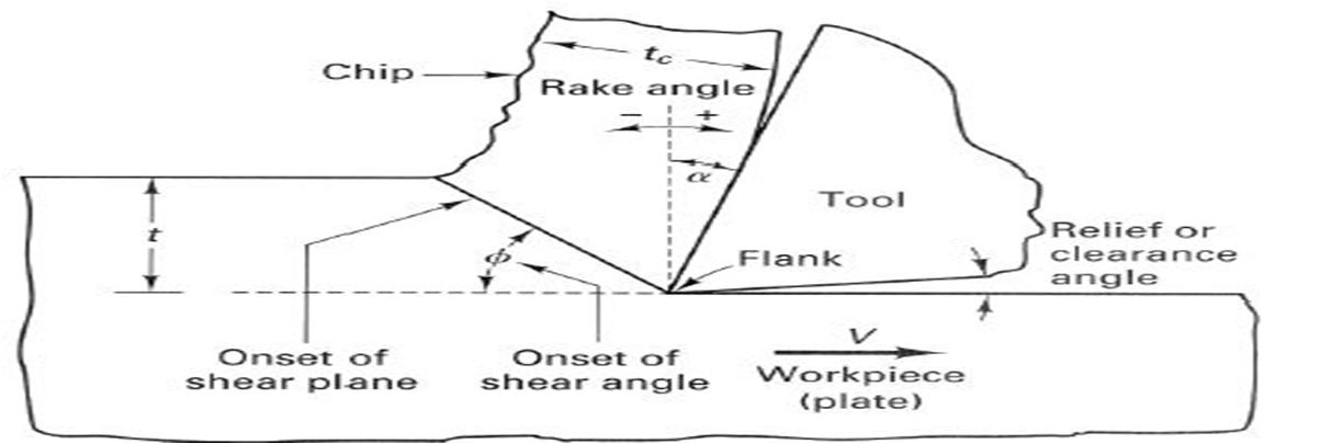
Fig. 1 Schematic of a 2D orthogonal machining process [7]

International
in
Science & Engineering Technology (IJRASET
ISSN: 2321 9653; IC Value: 45.98; SJ Impact Factor: 7.538
Volume 10 Issue IX Sep 2022 Available at www.ijraset.com
Table 1 Correlation of Orthogonal machining with turning [6] Turning Orthogonal Machining
Spindle speed , RPM
Feed rate , mm / rev
Depth of cut , mm
Cutting speed , m / min
Depth of cut , mm
Out of plane thickness , mm
Cutting Force , N Cutting Force , N Feed force , N Thrust force , N
Nose radius, mm Nose radius, mm Rake angle, degree Rake angle, degree
Investigation on the effect of process parameters on the machining process is one of the major outcomes of this research work. Full factorial design is used to obtain all possible combinations of process parameters, and Analysis of Variance (ANOVA) is used to analyze the effect of parameters on the cutting responses.
The prime objective of this work is to develop a detailed FE model for high speed machining of Inconel 740H and Haynes 282 alloys, and identify the optimal values of process parameters that would enable machining in a ductile regime.
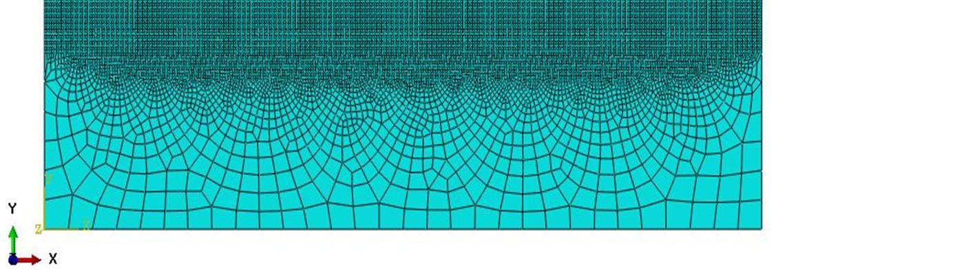
The model is developed using a commercially available FE package Abaqus/Explicit. The specimen is modeled as 2D deformable and the cutting tool is modeled as analytically rigid. The machining process is treated as a coupled thermo mechanical problem, with the domain meshed using CPE4RT elements (4 noded plane strain, thermally coupled quadrilateral element, with bilinear displacement and temperature).The primary degrees of freedom are evaluated at the nodes, and secondary and tertiary degrees of freedom are evaluated at the integration points. The elements use reduced integration scheme to lower the computational expensiveness.
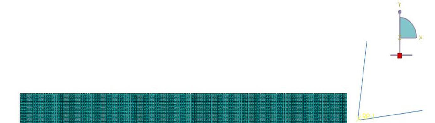
The workpiece model (Figure 2) is partitioned in such a way that, a structured mesh is used in areas where the response is measured and a free mesh is used in the remaining part of the domain. This, again, helps in reducing the computational cost. The tool and workpiece are initially maintained at a room temperature of 200C. Appropriate boundary conditions are applied on the workpiece and the tool, with the bottom and left edges of the workpiece being fixed with respect to all degrees of freedom, and the cutting tool assigned with an appropriate translation velocity derived from the concepts of orthogonal machining. The temperature distribution arising from the cutting operation is computed during the simulation. In order to effectively capture the machining responses at the primary shear zone, a minimum of 10 elements are used along the depth of cut with a good aspect ratio.
A surface to surface interaction is defined between the tool and the workpiece. As per contact criteria [13 14], tool is defined as the master and workpiece is defined as the slave. The contact algorithm used here is, penalty contact with a coulomb friction model.
ISSN: 2321 9653; IC Value: 45.98; SJ Impact Factor:
10 Issue IX Sep 2022 Available at www.ijraset.com
developed for high speed machining of advanced ultra super critical alloys (Inconel 740H and Haynes 282). Initially, the model
In the presented work, a detailed finite element model

validated for the titanium alloy (Ti 6Al 4V) by comparing the obtained results with the numerical
[6].
1)
model is then extended for the case of A USC alloys.
obtained at the primary shear zone (tool workpiece interface) as shown in figures 3 The type of
The model results indicate that the maximum value
in nature for the cutting conditions mentioned The results indicate a peak value of
Mises stress
developing at the primary shear zone.
The model results
International
Science & Engineering Technology (IJRASET
ISSN: 2321 9653; IC Value: 45.98; SJ Impact Factor: 7.538 Volume 10 Issue IX Sep 2022 Available at www.ijraset.com
a) Primary Validation of Model: The results obtained for Ti 6Al 4V alloy are correlated with the results from A. Ramesh et. al [6], corresponding to a spindle speed of 1600 rpm and a depth of cut of 2.75 mm. Table 2 demonstrates the model validation for two different cases of feed rates. The validation, results in a percentage of deviation of less than 4, which clearly indicates sufficient model accuracy.
TABLE 2
Primary validation of model for Ti 6Al 4V alloy Spindle speed = 1600 rpm (cutting speed = 125 m/min), Depth of cut = 2.75 mm Feed Rate Case 1: 0.1 mm/rev Case 2: 0.2 mm/rev
Cutting force: simulations 302.4 N 542.5 N Cutting force: literature [6] 292.5 N 522.6 N
% Deviation of results 3.4 3.8
With the success attained in modeling orthogonal machining of titanium alloy, the developed model is further extended for the case of A USC alloys.
2) Results for A USC Alloys Haynes 282: As mentioned above, the developed model is extended for the case of Haynes 282 with appropriate modifications to the thermal and physical properties The following set of parameters for machining and tool geometry is selected (Table 3) based on the motivation from Marcos Rodriguez Millan et al [16]
TABLE 3
Cutting parameters and tool geometry
Parameters Levels
Cutting Speed (Vc), m/min 90 (950 rpm); 180 (1900 rpm); 250 (2650 rpm)
Feed Rate (f), mm/rev 0.05; 0.1; 0.15 Rake Angle (α), degree 5; 0; 8 Nose Radius (r), mm 0.01; 0.025 Depth of Cut (d), mm 2
As indicated in table 3, three levels of cutting speed, feed rate, and rake angle, and two levels of nose radius are selected for performing the simulations. The depth of cut is maintained at a constant value of 2 mm. For obtaining an effective combination of process parameters, a full factorial design of experiments (DOE) approach is used (Tool used: Minitab).
Fig. 5
Mises
distribution in
180 m/min, f = 0.05 mm/rev, d = 2 mm,
= 0
, r = 0.025
ISSN: 2321 9653; IC Value: 45.98; SJ Impact Factor: 7.538 Volume 10 Issue IX Sep 2022 Available at www.ijraset.com
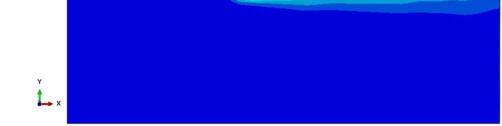
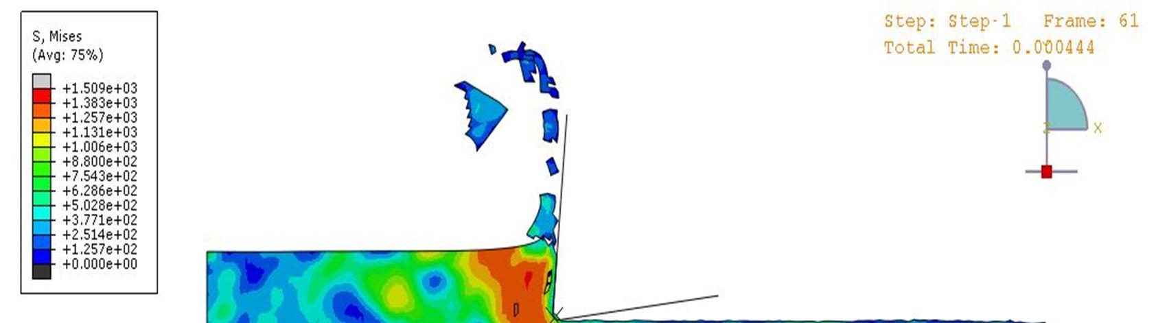
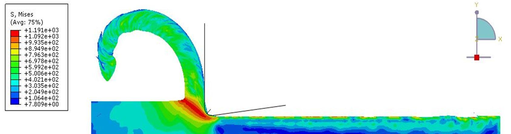
The contour plots for Von Mises stress distribution in Haynes 282 are shown in figures 5. The trend in the effective stress distribution is found to be similar as in the case of Ti 6Al 4V. However, a reduction of about 22% in the peak value is observed in Haynes 282 compared to the titanium alloy. It has to be understood that, a much higher value of cutting speed is used for the case of Haynes 282.
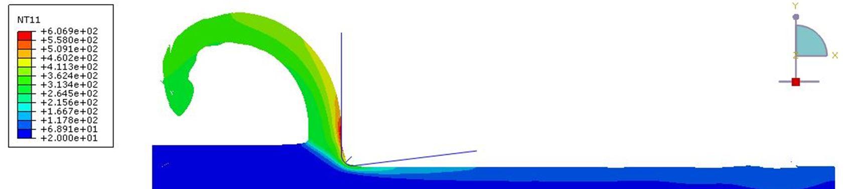
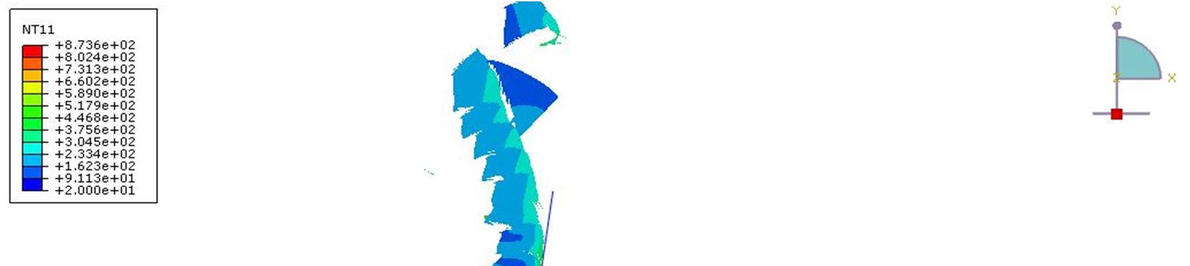
The trend in the temperature distribution is also found to be similar as in the case of the titanium alloy. Figure 6 shows the temperature distribution for varying process parameters. The peak value of temperature at the secondary shear zone is found to vary in the range of 600oC to 640oC.
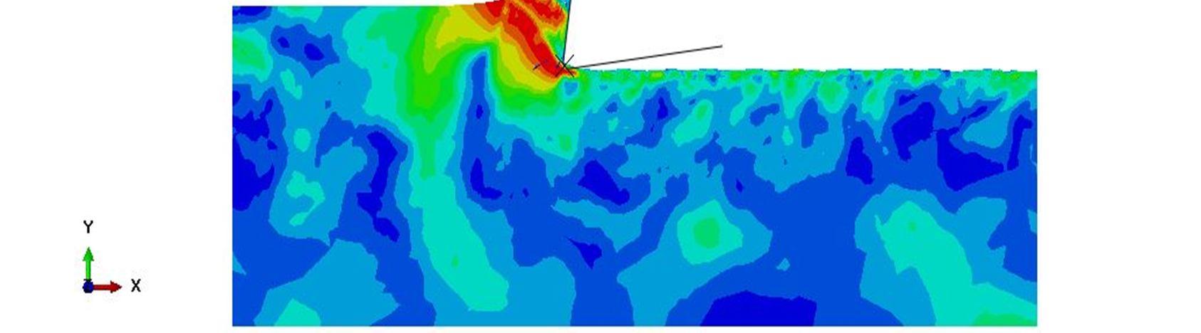
Fig. 6 Temperature distribution in Haynes 282: Vc= 180 m/min, f = 0.05 mm/rev, d = 2 mm, α = 0o, r = 0.025 mm
The numerical results indicate a continuous chip flow for the case of Haynes 282 corresponding to lower feed rates, smaller nose radii, and positive rake angles when machining is performed in the high speed range
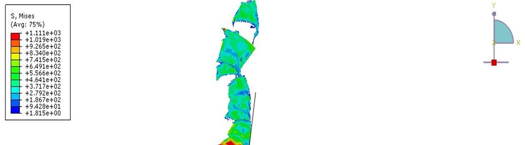
3) Results for A USC Alloys Inconel 740H: As mentioned, the developed model is extended for the case of Inconel 740H as well, with appropriate modifications to the properties. The simulations are performed for the same set of cutting conditions (Table 3) as in the case of Haynes 282. The contour plots for the Von Mises stress and temperature distribution in Inconel 740H are shown in figures 7 & 8. The peak values of effective stress and temperature are observed in the similar locations as in the case of Haynes 282.
Fig. 7 Von Mises stress distribution in Inconel 740H: Vc= 180 m/min, f = 0.1 mm/rev, d = 2 mm, α = 8o, r = 0.01 mm
ISSN: 2321 9653; IC Value: 45.98; SJ Impact Factor: 7.538 Volume 10 Issue IX Sep 2022 Available at www.ijraset.com
Cutting speed is found to have a direct influence on the heat generated at the tool chip interface. Temperature at the secondary shear zone is found to increase with the increase in cutting speed. This may be due to the reduction in the percentage of heat conducted to the work piece as a result of insufficient time for heat transfer. This, hence, reduces the chance for material hardening. Contrary to the type of chip formation in Haynes 282, serrated type chips are formed in Inconel 740H. This clearly indicates the ease of machining of Inconel 740H compared to Haynes 282. A detailed chip morphological study is also undertaken for further understanding on the machinability of the alloys (discussed in section 5).

The influence of machining parameters on the cutting force developed is investigated. The numerical results indicate feed rate to have the largest influence on increasing the cutting force compared to the remaining parameters. This can be attributed to a larger volume of the workpiece material getting engaged with the tool in unit time as the feed rate is increased. Cutting speed is found to have no significant influence on cutting force developed in either of the alloys. This may be due to the fact that since the cutting operation is already performed in the high speed range, the initial inertial resistance offered by the workpiece material is already taken care of. An increase in nose radius, on the other hand, is found to increase the cutting force in either of the alloys. This points to the larger resistance offered by the workpiece against a relatively blunt tool Positive rake angles are found to increase the ease of machining of the alloys. This is due to a reduction in the ‘Ploughing effect’ at the primary shear zone on increasing the positive rake angle. As Inconel 740H and Haynes 282 alloys are equally qualified for the A USC applications, the next task is to determine the comparative machinability of each material. It is observed that, for a cutting speed of 90 m/min (950 rpm) with all other cutting parameters kept constant (Figure 9), Haynes 282 alloy required around 62% higher cutting force than Inconel 740H. However, increasing the cutting speed to a range of 180 250 m/min (1900 2650 RPM) is found to further increase the cutting force by about 65 70 % in Haynes 282 compared to Inconel 740H.
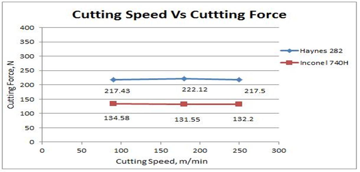
Fig. 9 Inconel 740H Vs Haynes 282; f = 0.05 mm/rev, α = 8o, r = 0.01 mm
Technology (IJRASET)
ISSN: 2321 9653; IC Value: 45.98; SJ Impact Factor: 7.538 Volume 10 Issue IX Sep 2022 Available at www.ijraset.com
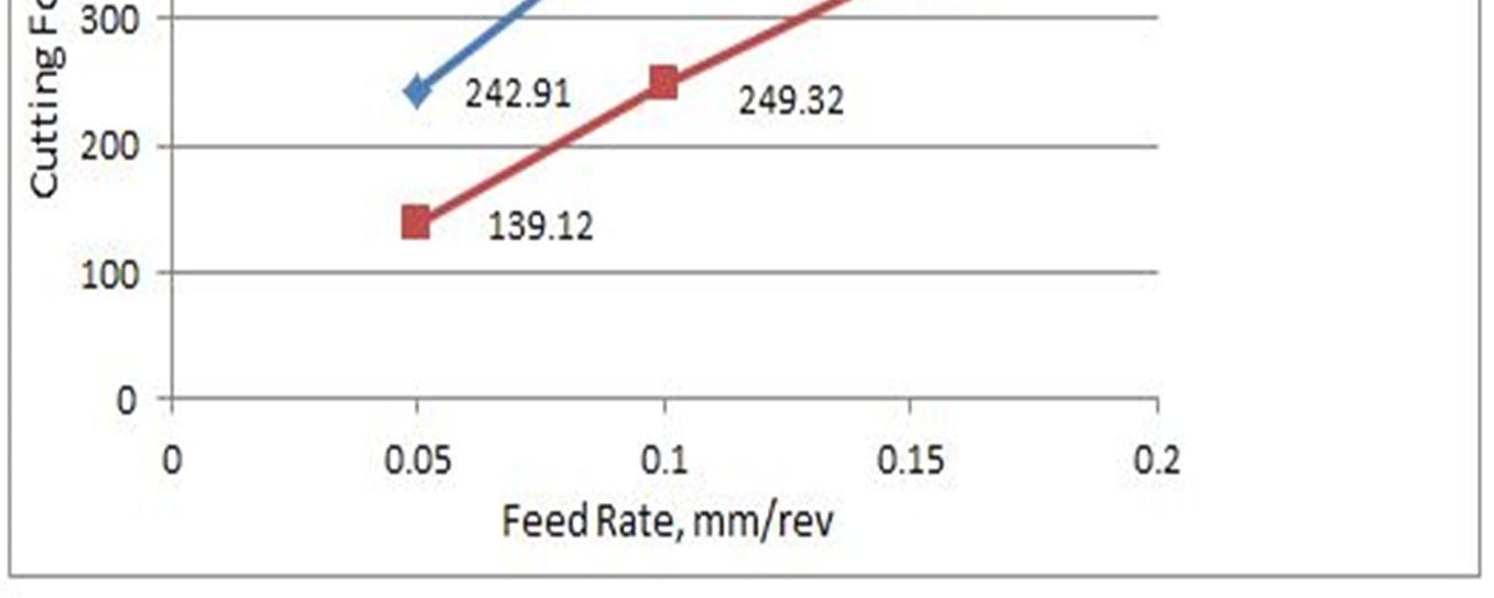
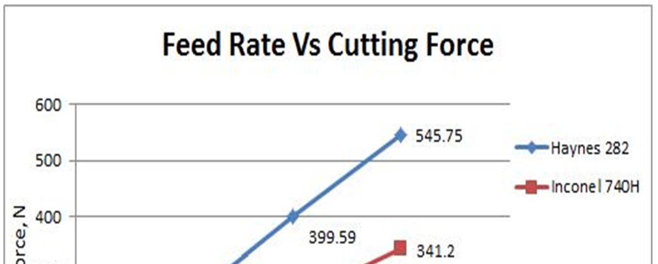
On the other hand, feed rate is found to have a significant influence on the cutting force developed in either of the alloys. For a feed rate ranging from 0.05 0.15 mm/rev with all other parameters kept constant, the cutting force required for machining Haynes 282 is found to increase by a range of 60 75 % compared to Inconel 740H (Figure 10)
Nose radius and rake angle are found to have a similar effect on the increasing cutting force requirement of Haynes 282 compared to Inconel 740H. When the nose radius is varied from 0.01 to 0.025 mm, a corresponding increase of about 69 to 75% in cutting force is observed in Haynes 282 compared to Inconel 740H. When the rake angle is varied from +8o to 5o, the cutting force is found increase from 69 % to 78 % more in Haynes 282 in comparison with the other alloy.
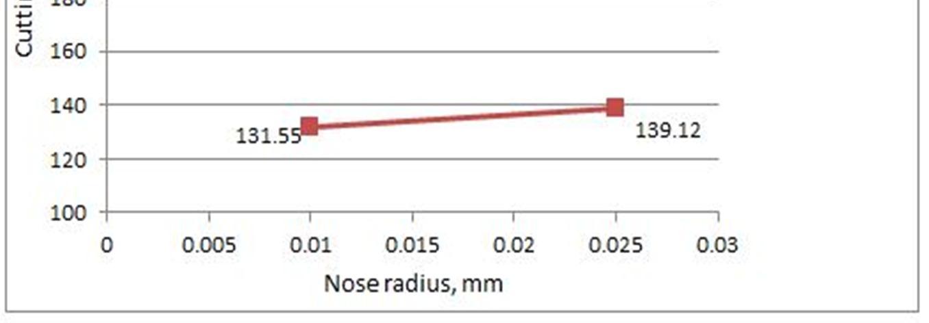
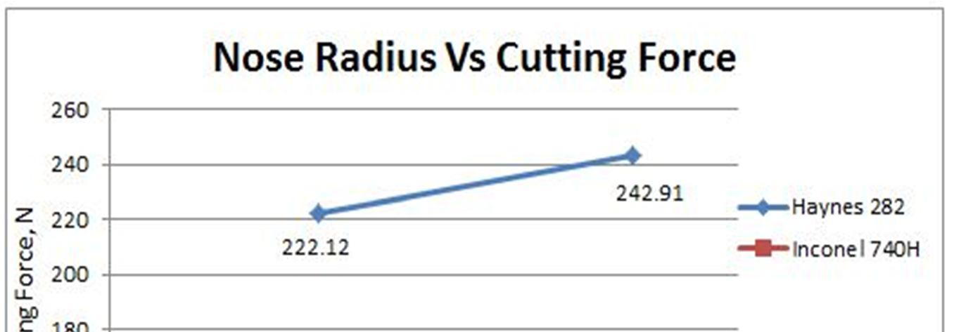
Fig. 10 Inconel 740H Vs Haynes 282; Vc = 180 m/min, α = 8o, r = 0.025 mm
Fig. 11 Inconel 740H Vs Haynes 282; f = 0.05 mm/rev, α = 8o, Vc = 180 m/min
ISSN: 2321 9653; IC Value: 45.98; SJ Impact Factor: 7.538
10 Issue IX Sep 2022 Available at www.ijraset.com
Fig. 12 Inconel 740H
282; f = 0.05 mm/rev, r = 0.01 mm, Vc = 180 m/min
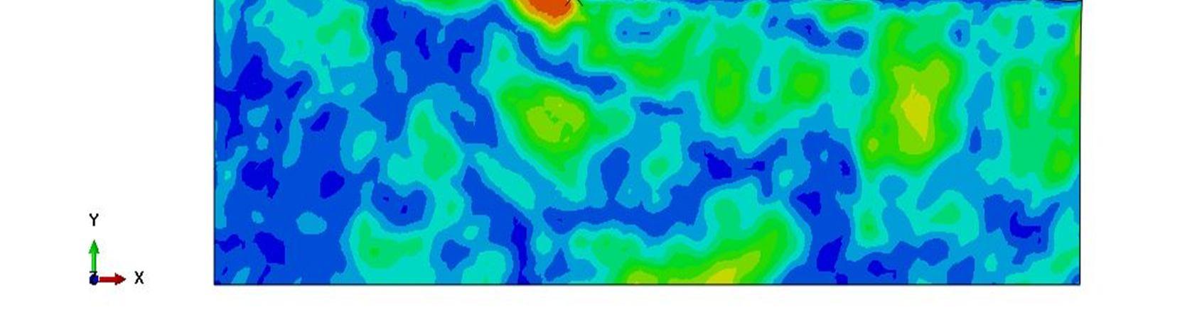
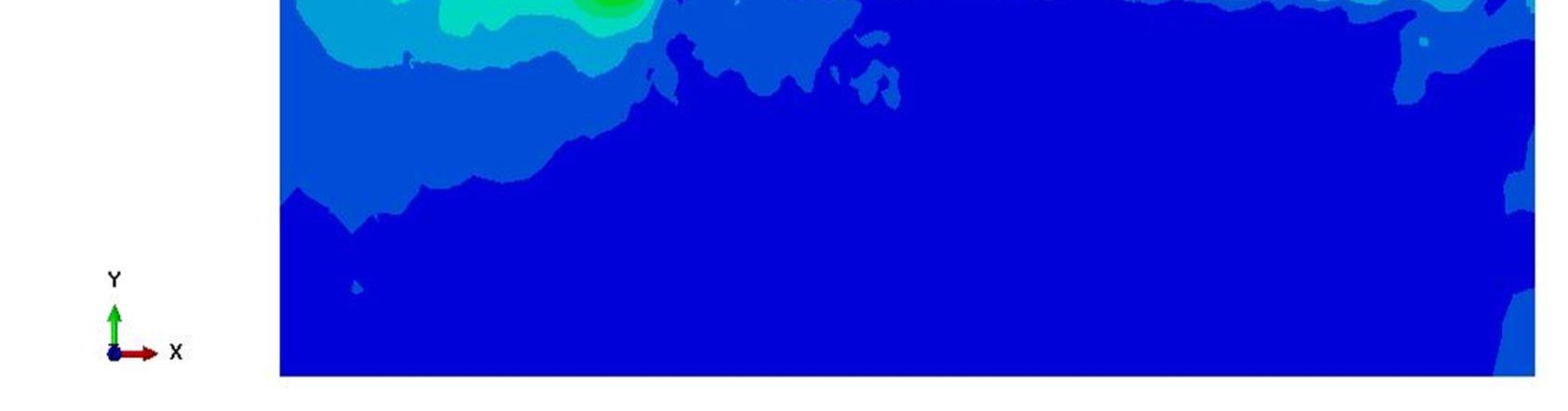
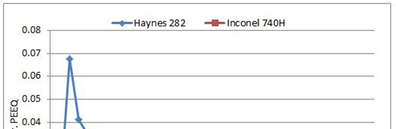
The presented work also investigates the influence of cutting parameters on trend of surface finish of the machined surface than the absolute value of surface roughness (Ra). The methodology used for measuring the trend of surface finish is based on the distribution of equivalent plastic strain (PEEQ) on the machined surface The procedure involves evaluation of the variance of PEEQ at all the surface nodes of the machined surface PEEQ is a measure of the effective plastic strain (permanent deformation) that a material would undergo upon loading. The variance of PEEQ is plotted against the range of cutting parameters for studying the trend of surface finish [6] Authors attempted to numerically identify the trend of surface finish rather than predicting the absolute value. In fact, this approach gave a clear understanding of trend of surface finish among Inconel 740H and Haynes 282. Equations (1) and (2) show the relations between PEEQ, equivalent plastic strain rate ( ), and plastic strain rate ( ).
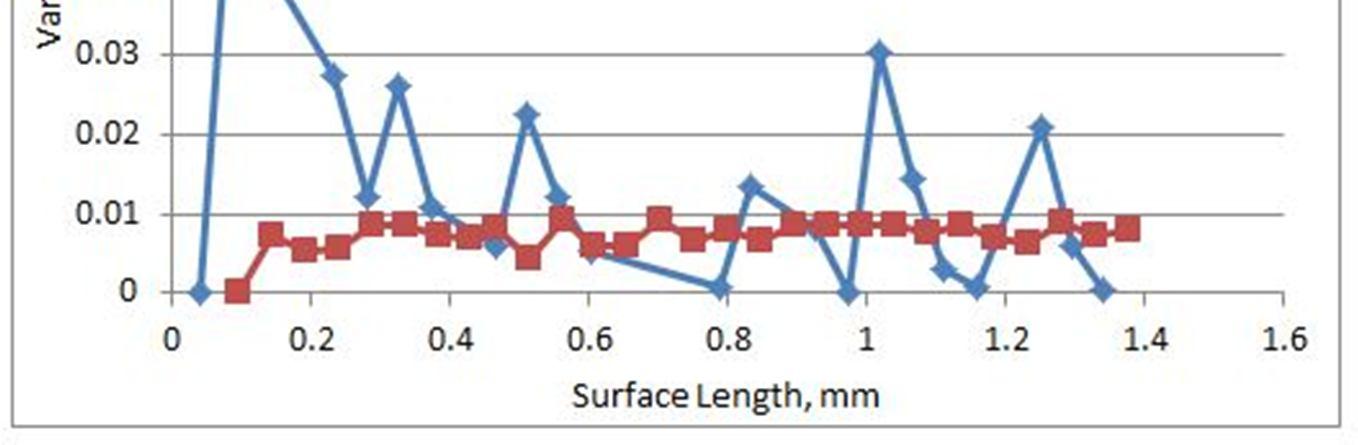
The above mentioned PEEQ calculations are numerically performed by the solver at each increment. Figures 13 and 14 show the comparison of surface finish achieved during high speed machining of Inconel 740H and Haynes 282 for two different rake angles From the trend of var (PEEQ) plots, it can be understood that Inconel 740H has a much better surface finish than Haynes 282 in the given range of cutting parameters [16].
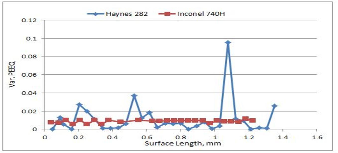
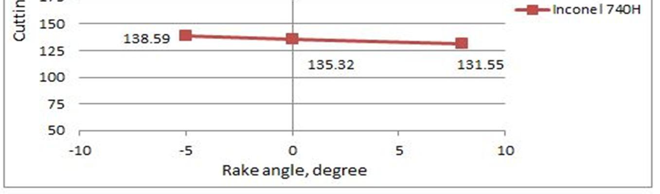
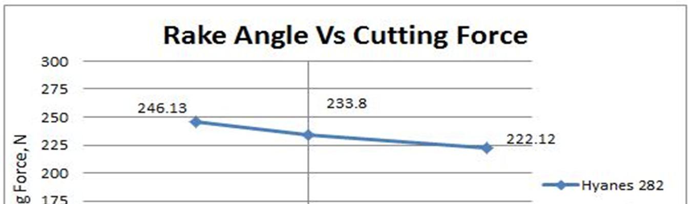
Figure 13 Inconel 740H
Haynes 282; f = 0.05 mm/rev, r = 0.01 mm, Vc= 180 m/min, α = 0
(IJRASET
ISSN: 2321 9653; IC Value: 45.98; SJ Impact Factor: 7.538 Volume 10 Issue IX Sep 2022 Available at www.ijraset.com
Fig. 14 Inconel 740H Vs Haynes 282; f = 0.05 mm/rev, r = 0.01 mm, Vc = 180 m / min, α = 8o
In addition to cutting force and trend of surface finish, the rate at which material is removed MRR, is also an important factor that needs to be considered for reducing the production time. Therefore, the influence of cutting parameters on MRR of the alloys is also investigated.
The results indicate that, MRR of the alloys has a direct proportionality with cutting speed and feed rate. On the other hand, nose radius is found to have an inverse effect on MRR. Positive rake angles are found to increase the MRR of materials. All the above behaviors can be correlated with the case of cutting force which is already mentioned. However, it is interesting to note that Haynes 282 has a higher MRR than Inconel 740H. This can be attributed to a larger volume of material being removed per unit time for the case of Haynes 282 due to an increasing cutting force requirement.
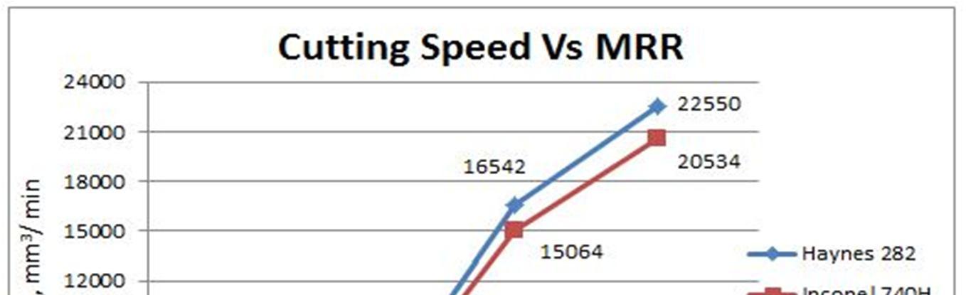
For a cutting speed of 90 m/min (950 rpm) with all other cutting parameters kept constant (Figure 15), it is observed that Haynes 282 alloy has around 10% higher material removal rate than Inconel 740H. However, increasing the cutting speed to a range of 180 250 m/min (1900 2650 rpm) is found to further increase the MRR by about 10 12 % in Haynes 282 compared to Inconel 740H. On the other hand, for the case of feed rate (Figure 16) ranging from 0.05 0.15 mm/rev with all other parameters kept constant, the MRR in machining Haynes 282 is found to increase by a range of about 6.0 9.0 % when compared to Inconel 740H.
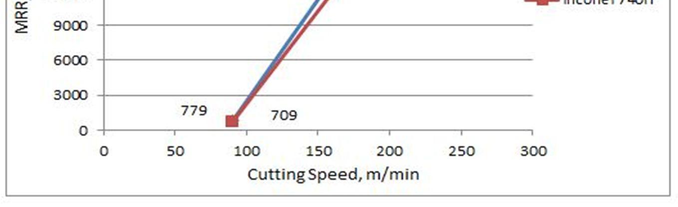
Fig. 15 Inconel 740H Vs Haynes 282; f = 0.05 mm/rev, α = 8o, r = 0.01 mm
(IJRASET
ISSN: 2321 9653; IC Value: 45.98; SJ Impact Factor: 7.538 Volume 10 Issue IX Sep 2022 Available at www.ijraset.com
Fig. 16 Inconel 740H Vs Haynes 282; Vc = 180 m/min, α = 8o, r = 0.025 mm
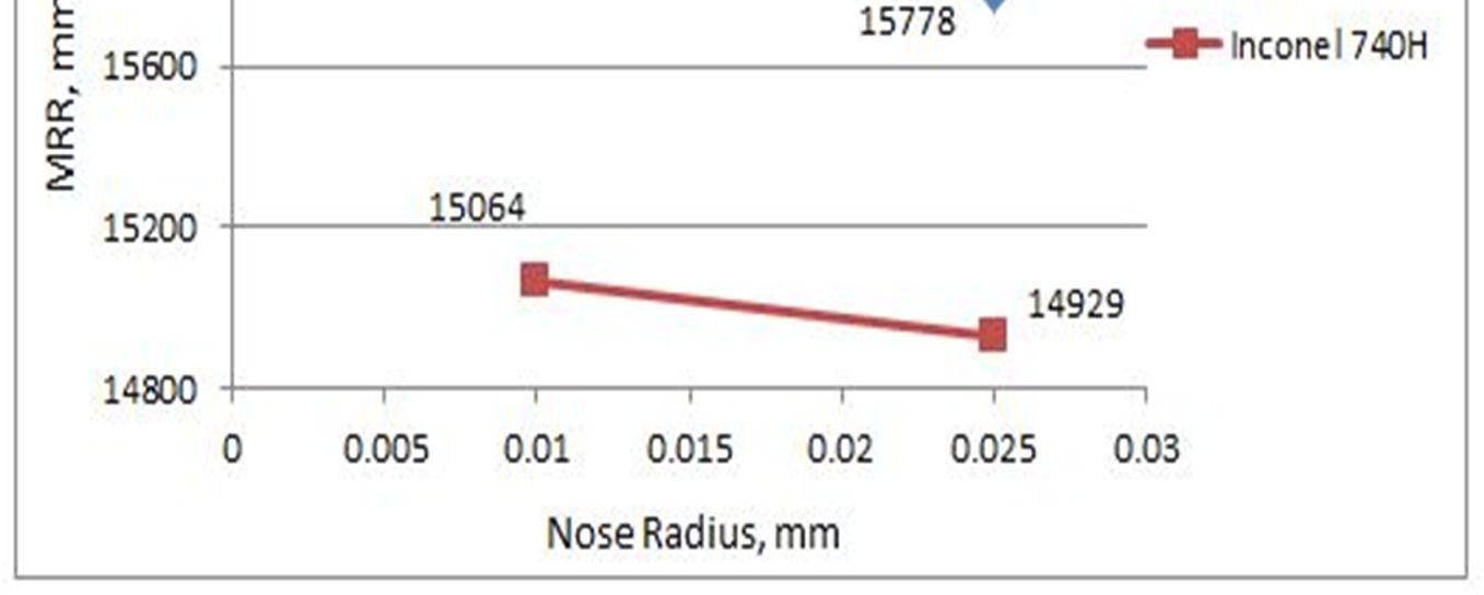
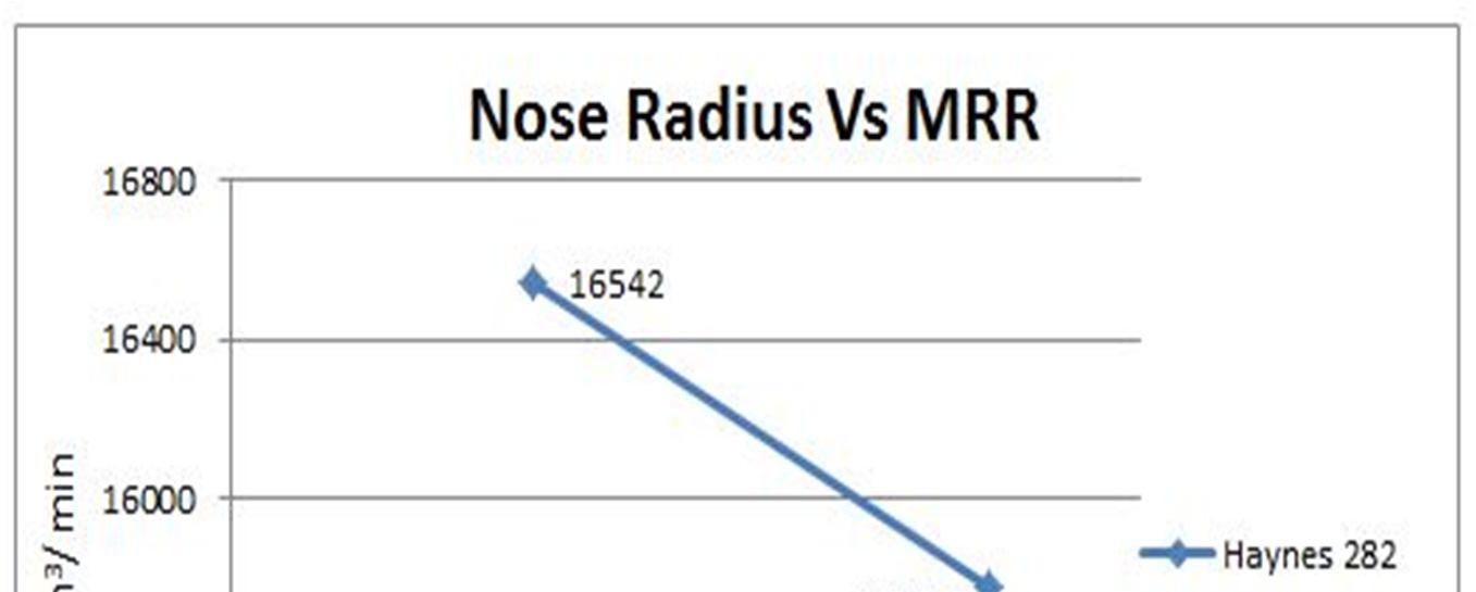
Figure 17 shows that nose radius has a negative effect on MRR for either of the alloys. For a range of nose radius from 0.025 to 0.01 mm with all other cutting parameters kept constant, a corresponding increase of about 6 to 10% in MRR is observed in Haynes 282 when compared to Inconel 740H.
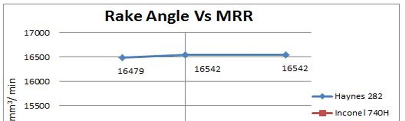
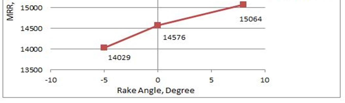
Rake angle (Figure 18) is observed to have no significant influence on the MRR of Haynes 282. However, it showed only about 7% (negligible) decrease in Inconel 740H on varying the rake angle from +8o to 5o On the other hand, Haynes 282 is observed to have a larger MRR than Inconel 740H, with a maximum increase of 17% between them. All the above, the numerically predicted MRR values showed only about 10% deviation from the empirical formula results
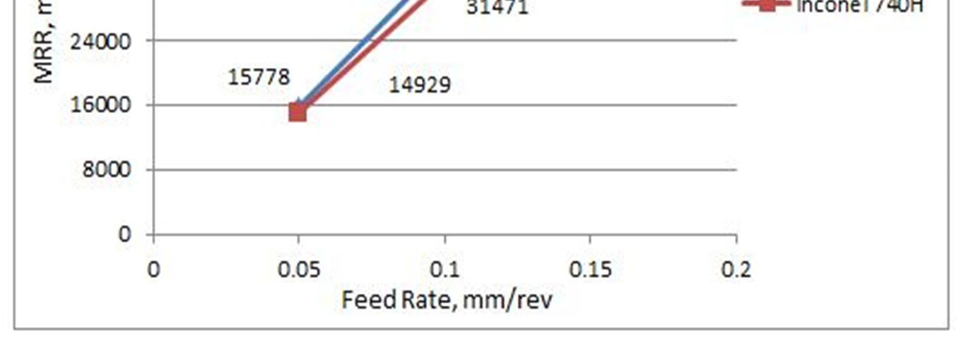
Fig. 17 Inconel 740H Vs Haynes 282; f = 0.05 mm/ rev, α = 8o, Vc = 180 m / min
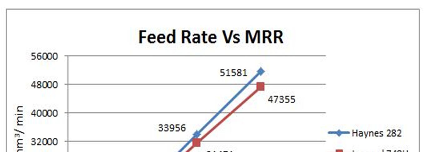
Fig. 18 Inconel 740H
Haynes
ISSN: 2321 9653; IC Value: 45.98; SJ Impact Factor: 7.538 Volume 10 Issue IX Sep 2022 Available at www.ijraset.com
f = 0.05
4) Main effect plots and mathematical model for cutting force and MRR
rev, r = 0.01 mm, Vc = 180 m / min
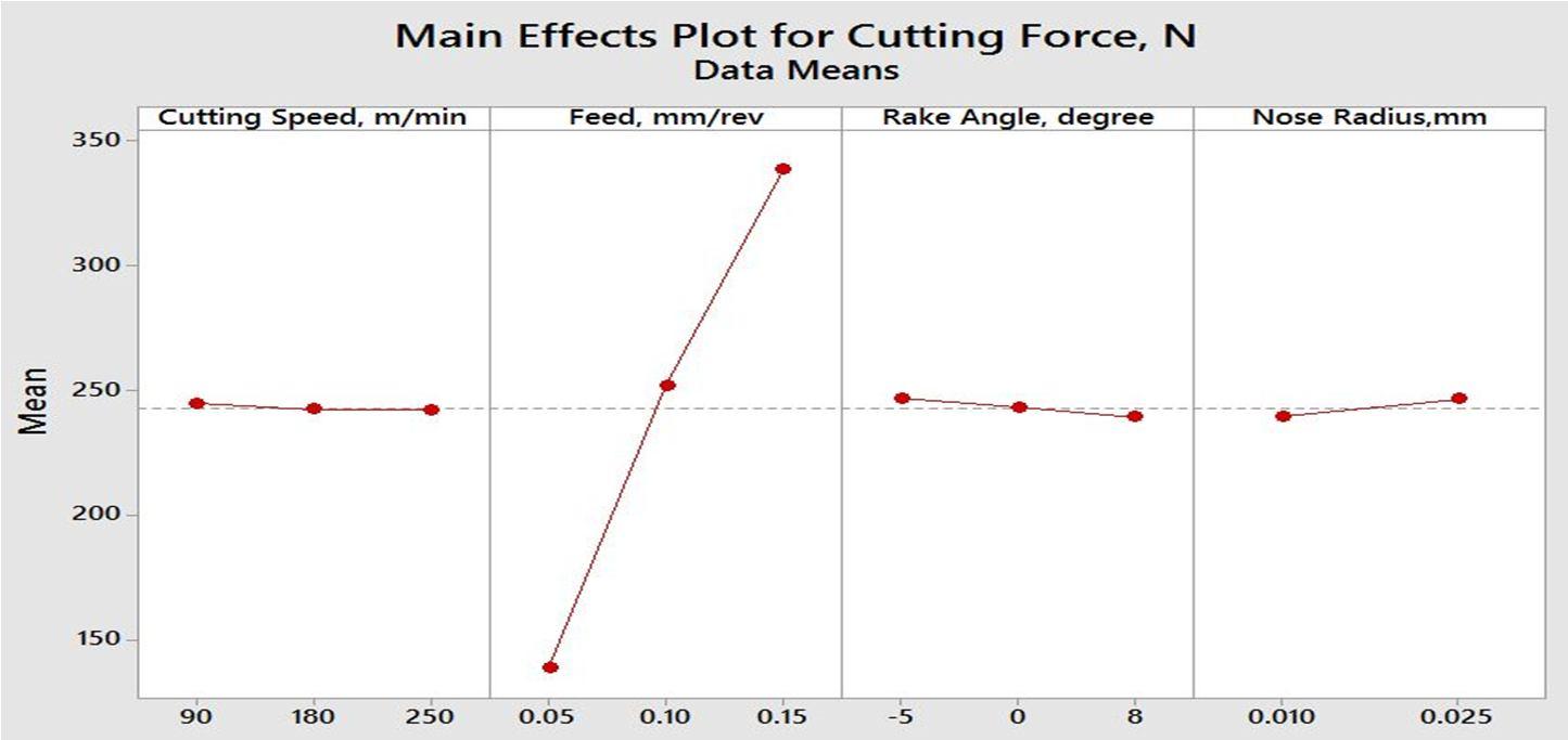
To signify the most influencing process parameter and to understand the subtle variations on the predicted value of output responses, the main effect plots are generated (Figures 19 & 20). These plots demonstrate only a single objective optimization of the cutting force The plots are found to be in good agreement with the explanations already provided in sections 3.2.1 and 3.2.3. As mentioned, feed rate is understood to be the most influencing parameter for cutting force. For the case of MRR, however, it can be seen that the cutting speed turns out to be the most influencing one for an initial range of up to 180 m/min, and beyond that, for feed rates higher than 0.1 mm/rev, feed rate turns out to be the most influencing parameter.
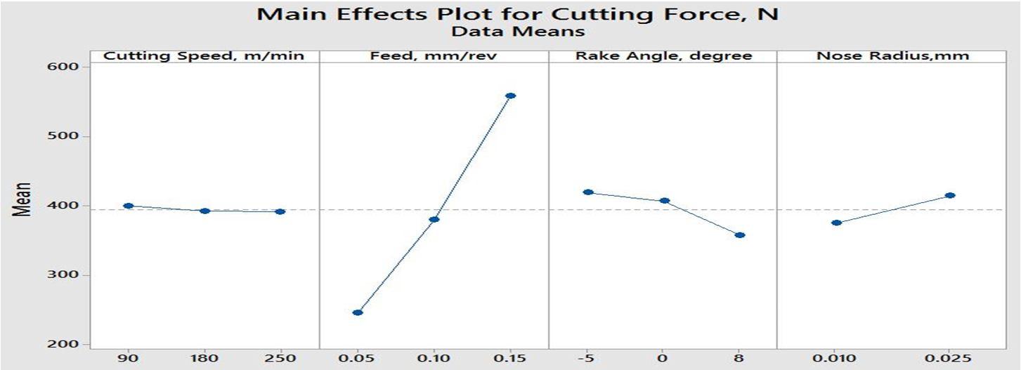
Fig. 19 Main effect plot for cutting force of Haynes 282 alloy
Fig. 20 Main effect plot for cutting force of Inconel 740H
(IJRASET
ISSN: 2321 9653; IC Value: 45.98; SJ Impact Factor: 7.538
Volume 10 Issue IX Sep 2022 Available at www.ijraset.com
Nose radius is found to have no significant influence on the MRR of either of the alloys. However, in the case of rake angle, increasing the rake angle beyond 00 is found to decrease the material removal rate for Haynes 282. On the other hand, for the case of Inconel 740H, the MRR is found to increase gradually with the increase in rake angle from negative to positive values. Regression equations are then generated to mathematically represent the influence of process parameters on the output responses. Equations (3) to (6) show mathematical models for cutting force and MRR, for the cases of Haynes 282 and Inconel 740H alloys, respectively.
= 48.5 0.0529 + 3137 4.859 +2658 (3)
= 3859 0017 + 19985 0579 + 460 (4)
= 50802+2760 + 282543 188 +84074 (5)
= 42911+247.7 + 243574 +215 41169 (6)
a better practical understanding and to filter out the optimum values of the process parameters, a multi objective optimization is performed (Figure 21) for the case of Inconel 740H The requirement is to simultaneously minimize the cutting force and maximize the material removal rate.
Fig. 21 Multi objective optimization plot for Inconel 740H
obtained optimum values of the cutting parameters are displayed below:
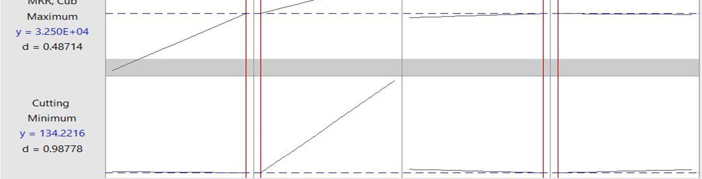
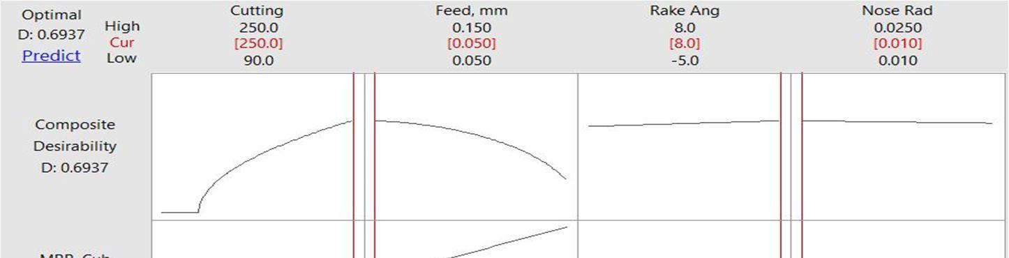
Cutting speed, Vc = 250 m/min (Spindle speed = 2650 rpm)
rate, f = 0.05 mm/rev
Rake angle, α = 8o
Nose radius, r = 0.01 mm
corresponding predicted values of the cutting force and MRR are 134.22 N and 3.25E04 mm3/min, respectively.
Mesh convergence study is performed to establish the independence of numerical results on the element size. For this purpose, the number of elements along the depth of cut is increased by 100% (and above), from the initial level of refinement. Table 4 depicts the results of the study performed on Inconel 740H alloy.
Cutting parameters
force, Fc (Coarser Mesh)
Cutting force, Fc (Finer Mesh)
Deviation
c = 180 m/ min 241.67 N 253.2 N 4.77
= 0.1 mm/ rev α = 8o r = 0.01 mm
Engineering Technology (IJRASET
ISSN: 2321 9653; IC Value: 45.98; SJ Impact Factor: 7.538 Volume 10 Issue IX Sep 2022 Available at www.ijraset.com
From the above table, it is evident that the percentage of deviation in results between the (n+1)th and the n th levels of refinement is less than 5%. This indicates that the results have become independent of the element size, and hence, the nth level of mesh refinement is indeed qualified for running simulations.
D. Experimental Validation (secondary) of Numerical Results for Haynes 282
The numerical results obtained for the case of Haynes 282 are correlated with the experimental results from Marcos Rodriguez Millan et al. [16], corresponding to a cutting speed of 180 m/min and a depth of cut of 2 mm. Table 5 demonstrates the validation for two different cases of feed rates. The results indicate a percentage of deviation of less than 5, which further emphasizes the accuracy of the model.
TABLE 5
Secondary validation of the FE model for Haynes 282
Cutting speed = 180 m/min , Depth of cut = 2 mm
Feed Rate Case 1: 0.1 mm/rev Case 2: 0.15 mm/rev
Thrust force: simulations 408.1 N 436.8 N
Thrust force: literature [11] 392 N 420 N
% Deviation of results 4.1 4.0
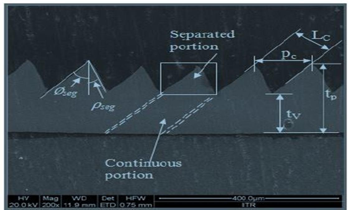
Chip morphology gives an additional accurate indication on the machinability of materials. High speed machining of hard to machine materials like Nickel based A USC alloys, results in the formation of serrated chips, provided the machining is performed in the ductile regime. Figures 11 to 14 (Section 3.1.3) indicate the formation of serrated chips for the case of Inconel 740H for the given range of cutting parameters. However, for the range of parameters shown in the corresponding Figures 7 to 10 (Section 4.1.2) for Haynes 282 do not correspond to such a chip formation. Figure 22 displays the various parameters that define chip morphology, viz., tooth pitch (Pc), peak height (tP), valley height (tV), tooth angle (localized shear (Øseg) and bulge (ρseg)), and cut chip length (Lc) (used to evaluate segmentation frequency).
Equation 17 shows the chip segmentation frequency, which is a measure of the number of serrations in unit time [10].
(17)
wherein, V is the chip speed and Pc is the tooth pitch. Chip speed is evaluated using cutting ratio; r = Lc/L and cutting speed Vc. Figure 23 shows the variation of peak height with respect to cutting speed for Inconel 740H and Haynes 282 The results obtained indicate that, peak height slightly reduces with the increase in cutting speed, which is desirable As the peak height reduces, the chip serration mechanism remains nominal. Therefore, the machinability can be improved by increasing the cutting speed.
(IJRASET
ISSN: 2321 9653; IC Value: 45.98; SJ Impact Factor: 7.538
Volume 10 Issue IX Sep 2022 Available at www.ijraset.com
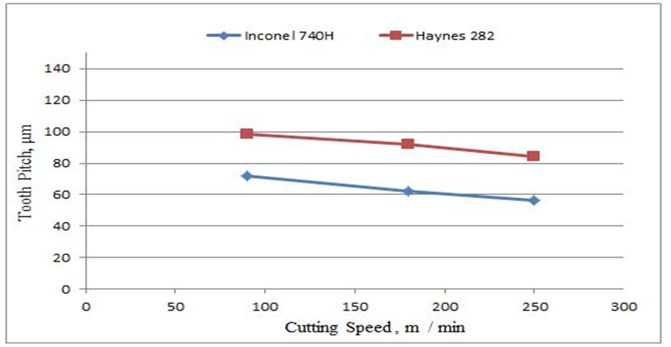
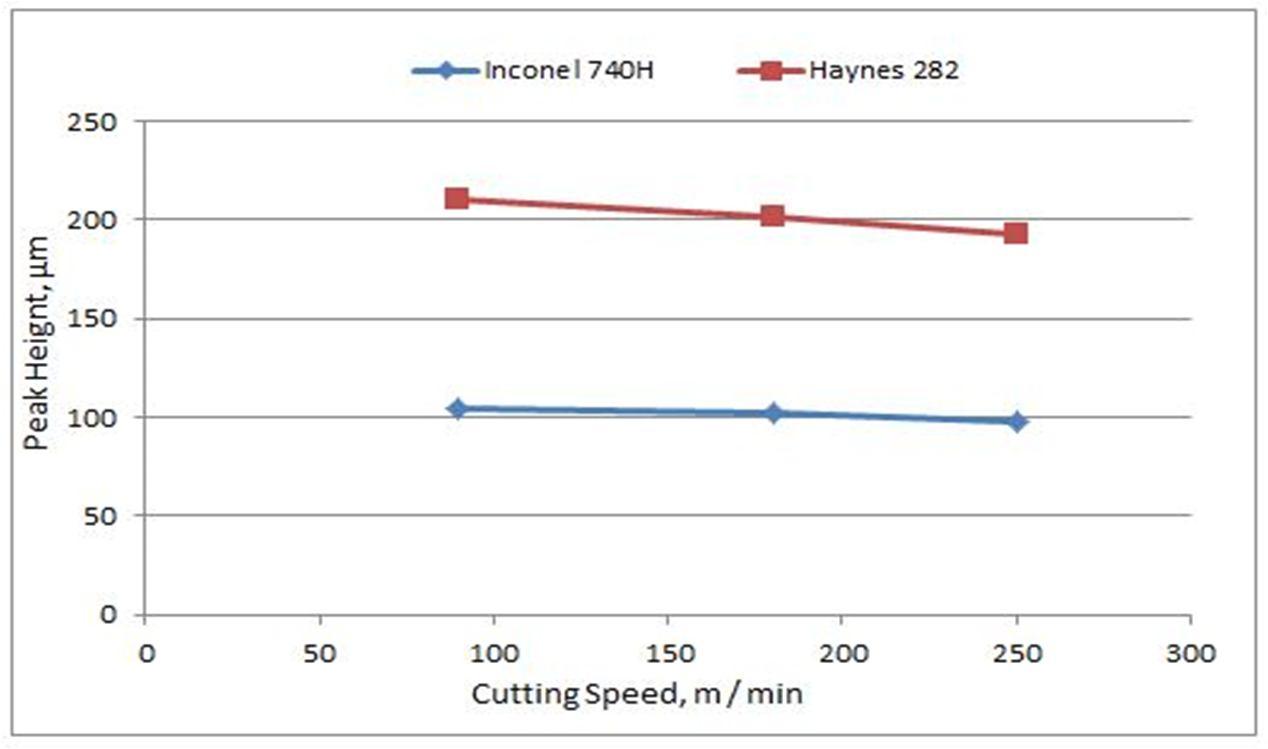
Figure 24 shows the effect of cutting speed on tooth pitch. It is observed that, tooth pitch decreases with increase in cutting speed. For better machinability, the tooth pitch needs to be minimal since it reduces the chance for chip breakability Further, as the tooth pitch reduces, the continuous portion of chip dominates the serrated portion.
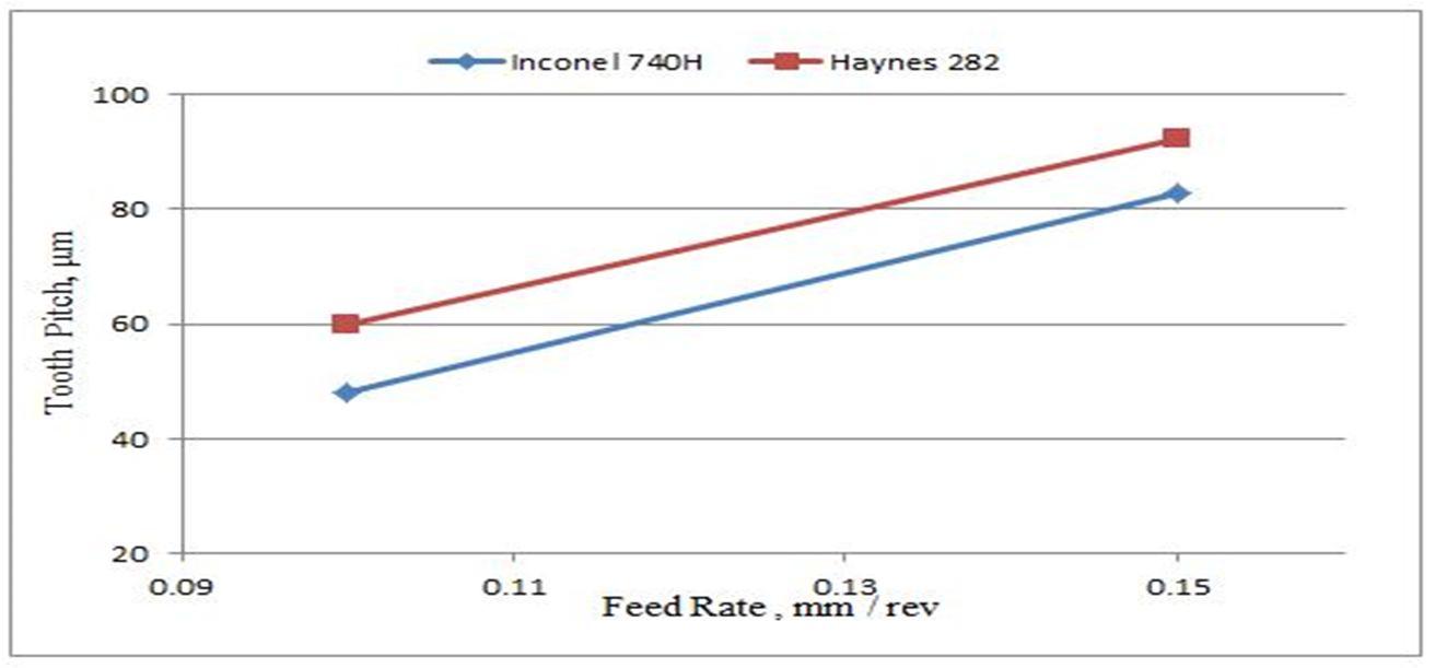
Figure 25 shows the influence of feed rate on tooth pitch for both the alloys. Tooth pitch is observed to have a direct proportionality with feed rate. Therefore, a higher feed rate may lead to chip breakability.
Fig. 25 Feed rate Vs Tooth pitch
(IJRASET
ISSN: 2321 9653; IC Value: 45.98; SJ Impact Factor: 7.538 Volume 10 Issue IX Sep 2022 Available at www.ijraset.com
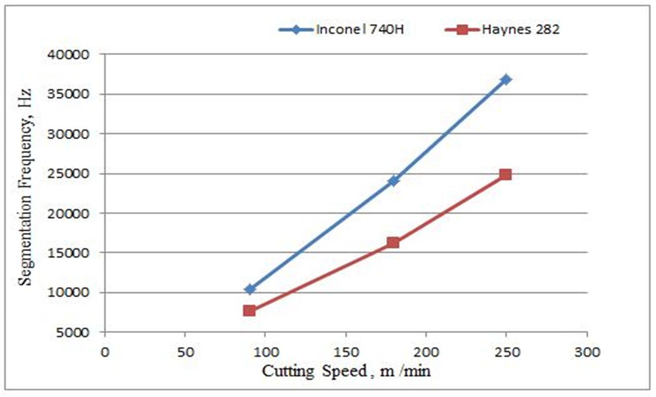
Figure 26 shows the effect of cutting speed on chip segmentation frequency. For both the alloys, the segmentation frequency is found to increase with cutting speed. It is desirable to have a higher segmentation frequency since that result in serrated chips. It can now be understood that, the chip segmentation frequency is inversely proportional to the tooth pitch.
Therefore, from the results we can conclude that, as the tooth pitch increases with the increase in feed rate, the segmentation frequency decreases and hence, the chance of chip breakability also increases.
The paper presents a detailed finite element model for simulating high speed machining of A USC qualified alloys: Inconel 740H and Haynes 282. The developed model is primarily validated for Ti 6Al 4V alloy using the numerical results from available literature. The validated model is then extended for the case of Inconel 740H and Haynes 282. These results are then further validated with the experimental results available from relevant literature for the corresponding alloys. Once the finite element model is successfully developed, optimization studies are performed to understand the influence of the cutting parameters like cutting speed, feed rate, nose radius, and rake angle on the output responses of cutting force, surface finish, and Material Removal Rate (MRR). Main effect plots indicate feed rate to have the most significant influence on cutting force and surface finish when compared to all the remaining parameters. Haynes 282 alloy is found to require about 60 80% larger cutting force than Inconel 740H for varying cases of process parameters. Similarly, results also indicate Inconel 740H alloy to have a significantly better surface finish than Haynes 282 in the given range of parameters. For the case of MRR, on the other hand, cutting speed and feed rate are found to have almost equal influence for both the alloys MRR is found to increase appreciably on increasing the cutting speed and feed rate. However, nose radius is found to have an inverse effect on the MRR. Similarly, positive rake angles are found to increase the MRR of either material. It is interesting to note that, although Inconel 740H is found to have a much lower cutting force and significantly better surface finish, Haynes 282 has a relatively higher material removal rate (6 17%) A multi objective optimization is also performed for Inconel 740H considering minimization of cutting force and maximization of MRR, simultaneously. The corresponding optimal values for the cutting parameters are thereby obtained Chip morphology studies are also performed in order to get an additional leverage towards the ductile regime machining of the A USC alloys. The influence of cutting parameters on chip morphology is also investigated. It is found that a serrated form of chips is a direct indication towards better machinability of these alloys in the high speed range. The results indicate a lower peak height, lower tooth pitch, and a higher segmentation frequency to be corresponding to larger cutting speeds and lower feed rates. Such a combination of parameters is found to result in a nominal chip serration and towards a reduction in the chances of chip breakability. On the overall, it may be concluded that for the given range of cutting parameters, Inconel 740H has a relatively better chip serration than Haynes 282. Therefore, considering all the numerical results obtained from the investigation, it may also be concluded that Inconel 740H has a relatively better machinability than Haynes 282 in the considered range of parameters
International Journal for Research in Applied Science & Engineering Technology (IJRASET)
ISSN: 2321 9653; IC Value: 45.98; SJ Impact Factor: 7.538
Volume 10 Issue IX Sep 2022 Available at www.ijraset.com
Authors extend a very profound gratitude to the Chair of the Department of Mechanical Engineering and Dean Engineering at Amrita School of Engineering, Coimbatore, India, for their wholehearted support and contributions for successfully completing the research work.
Ramakrishnan P A, Ajith Ramesh, and C S Sumesh declare that they have no conflict of interest.
[1] Robert Purgert, Jeffrey Phillips, Howard Hendrix, John Shingledecker, James Tanzosh, Materials for Advanced Ultra supercritical (A USC) Steam Turbines, US Department of Energy National Energy Technology (2016) 8 40.
[2] J.R. Robertson, Continued Developments in the Characteristics of Haynes 282 Alloy for Use in A USC Applications, Proceedings of the ASME Symposium (2018) 1 8.
[3] Carlos H. Lauro, Lincoln C. Brandao, Sergio L. M. Ribeiro Filho, Robertt A. F. Valente, J. Paulo Davim, Finite Element Method in Machining Processes: A Review. Modern Manufacturing Engineering, Materials Forming, Machining and Tribology (2015) 65 91.
[4] A.G. Mamalis, J. Kundrak, A. Markopoulos, D. E. Manolakos, On the finite element modeling of high speed hard turning. Int J Adv Manuf Technol 38. (2008) 441 446.
[5] Stenberg N, Proudian J, Numerical modelling of turning to find residual stresses. 14th CIRP conference model machining operations 8. (2013) 258 264.
[6] Ajith Ramesh, C S. Sumesh, P.M. Abhilash, Finite element modelling of orthogonal machining of hard to machine materials, Int. J. Machining and Machinability of Materials, Vol. 17. (2015) 543 565.
[7] David A. Stephenson, John S. Agapiou, Metal Cutting Theory and Practices. CRC Press, 2016.
[8] Bo Zhang, Mwangi Jessee Njora, Yoshiki Sato, High speed turning of Inconel 718 by using Ti Al N and (Al, Ti) N coated carbide tools, Int J Adv Manuf Technol (2018) 1 7.
[9] D.M. D'Addona, Sunil J Raykar, M. M. Narke, High speed machining of Inconel 718: Tool wear and surface roughness analysis, 10th CIRP Conference on Intelligent Computation in Manufacturing Engineering, Procedia CIRP 62, (2017), 269 274.
[10] K. Mile, Qualification of Ni Based Alloys for Advanced Ultra Supercritical Plants. Procedia Engineering 55, (2013), 214 220.
[11] Shailesh J. Patel, John J. deBarbadillo, Brian A. Baker, Ronald D. Gollihue, Nickel base super alloy for next generation coal fired AUSC power plants. Procedia Engineering 55, (2013), 246 252.
[12] C.S. Sumesh, A. Ramesh, Numerical Modelling and Optimization of Dry Orthogonal Turning of Al6061T6 Alloy. Periodica Polytechnica Mechanical Engineering, 62, (2018), 196 202.
[13] K. Krishnaprasad, C.S. Sumesh, A. Ramesh, Numerical Modeling and Multi Objective Optimization of Face Milling of AISI 304 Steel. Journal of Applied and Computational Mechanics, 5, (2019), 749 762.
[14] SIMULIA Abaqus Documentation, Dassault Systèmes, Providence, RI, USA, 2016.
[15] Trent EM, Wright PK, Metal cutting, 4th edn. Butterworth Heinemann, Woburn, MA, USA, 2000.
[16] Marcos Rodriguez Millan, Jose Diaz Alvarez, Richard Bernier, Jose Luis Cantero, Alexis Rusinek, Maria Henar Miguelez, Thermo Viscoplastic Behavior of Ni Based Superalloy Haynes 282 and its Application to Machining Simulation. MDPI, (2017), 1 17.
[17] Chen G, Ren C, Yang X, Jin X, Guo T, Finite element simulation of high speed machining of titanium alloy (Ti 6Al 4V) based on ductile failure model, Int J Adv Manuf Technol 56, (2011), 1027 1038.
[18] Johnson and Cook, Fracture Characteristics Of Three Metals Subjected To Various Strains, Strain Rates, Temperatures And Pressures. Engineering Fracture Mechanics, Vol. 21, (1985), 31 48.
[19] M. Demiral, T. Leemet, M. Hokka, V. T. Kuokkala, A. Roy, V.V. Silberschmidt, Finite Element Simulations of Split Hopkinson Test of Ti Based Alloy. Advanced Materials Research, 223, (2011), 296 303.
[20] John J. de Barbadillo, Properties of Inconel Alloy 740H for High Pressure Steam and Supercritical CO2 Applications. Proceedings of the ASME Symposium, (2018), 1 11.
[21] INCONEL ALLOY 740H Data sheet, Special Metals PCC Company Inc, 2017.
[22] HAYNES 282 ALLOY Data Sheet, Haynes International Inc, 2017
[23] Bao and Wierzbicki, On fracture locus in the equivalent strain and stress triaxiality space. In J Mechanical Sciences 46, (2004), 81 98.
[24] Vikas Upadhyay, P.K. Jain, N.K. Mehta, Comprehensive study of chip morphology in turning of Ti 6Al 4V. AIMTDR Conference, IIT Guwahati, (2014), 1 6.