
10 VIII August 2022 https://doi.org/10.22214/ijraset.2022.46224

Abstract: The design and analysis of earthquake resistant structures play importance factor all over the world. Hilly regions such as Ambikapur, Koriya, Dantewada & Jagdalpur district as a part of Chhattisgarh are more vulnerable in terms of seismic collapse structure in recent years and demand of high rise structures with irregularity as given below is increasing now day due to high land cost & infrastructure there is much need or require of earthquake stability check. The paper is about analysis of different RCC Frames along with different cases of shear wall and X bracing. The objectives of this paper are to model the asymmetry frame with different cases in respect to location of retrofitting, to examine seismic parameters such as story shear, displacement, compressive stress, story drift in order to check stability and to validate the best suitable location for asymmetry building and finding out their limitation.
Keywords: Asymmetry, Bracings, Shear wall I. INTRODUCTION TO SEISMIC ANALYSIS
International Journal for Research in Applied Science & Engineering Technology (IJRASET) ISSN: 2321 9653; IC Value: 45.98; SJ Impact Factor: 7.538 Volume 10 Issue VIII August 2022 Available at www.ijraset.com 478©IJRASET: All Rights are Reserved | SJ Impact Factor 7.538 | ISRA Journal Impact Factor 7.894 |
Investigation of Building having Shear Wall and Bracings using Linear Dynamic Analysis
3) Severe (and infrequent) shaking with damage to structural elements, but with NO collapse (to save life and property inside/adjoining the building).
Fig. 1. Earthquake Resistant Designs
1) Minor (and frequent) shaking with no damage to structural and non structural elements;
Seismic analysis is a subset of structural analysis and is the calculation of the response of a building structure to earthquakes. It is part of the process of structural design, earthquake engineering or structural assessment and retrofit in regions where earthquakes are prevalent. Many researches have been conducted on the seismic analysis and still it is continuing, because more we try to learn more, we can minimize the damages and save the lives by varying different parameters of structural elements. During an earthquake, failure of structure starts at points of weakness. This weakness arises due to discontinuity in mass, stiffness and geometry of structure. The structures having this discontinuity are termed as Irregular structures Irregularities in plan are one of the major reasons of failures of structures during earthquakes. To perform well in an earthquake a building should possess four main attributes namely simple and regular configuration and adequate lateral Strength, stiffness and ductility. Buildings having simple regular geometry and uniformly distributed mass and stiffness in plan as well as elevation, suffer much less damage than buildings with irregular configuration. The traditional earthquake resistant design philosophy requires that normal buildings should be able to resist:
Amir Abbasi1 , Shrikant Mishra2 1PG Scholar, 2Assistant Professor, Department of Civil Engineering SSTC, Bhilai, India
2) Moderate shaking with minor damage to structural elements, and some damage to non structural elements; and


NONANALYSISLINEAR
ANALYSISSEISMICOFMETHODS
LINEAR ANALYSIS LINEARANALYSISSTATIC EQUIVALENTMETHODSTATIC LINEARANALYSISDYNAMIC HISTORYELASTICSPECTRUMRESPONCEANALYSISTIMEANALYSIS
International Journal for Research in Applied Science & Engineering Technology (IJRASET) ISSN: 2321 9653; IC Value: 45.98; SJ Impact Factor: 7.538 Volume 10 Issue VIII August 2022 Available at www.ijraset.com 479©IJRASET: All Rights are Reserved | SJ Impact Factor 7.538 | ISRA Journal Impact Factor 7.894 |
NON LINEAR ANALYSISSTATIC PUSHOVERANALYSIS NON DYNAMICLINEARANALYSIS INELASTIC TIME HISTORY ANALYSIS
Fig. 2 Flow Chart of Methods of Seismic Analysis
The selection of seismic analysis method type to analyze the structure depend upon the external action, the behavior of structural material and type of structural modal selected. In bureau of Indian Standards, these four methods of analysis are defined i.e., Linear Static Analysis, Linear Dynamic Analysis, Non Linear static analysis & non Linear dynamic analysis.
III. LITERATURE SURVEY
The following are the literature study for RCC building having shear walls & bracing Dr. S. A. Halkude, Mr. M. G. Kalyanshetti, Mr. V. D. Ingle (2013) in their paper has studied that in hilly regions, engineered construction is constrained by local topography resulting in the adoption of either a step back or step back & set back configuration as a structural form for buildings. The adopted form invariably results in a structure which is irregular by virtue of varying column heights leading to torsion and increased shear during seismic ground motion. The Response spectrum analysis (RSA) is carried out namely step back frame sand step back & set back building frames on sloping ground with varying number of bays and hill slope ratio. The dynamic response i.e. Fundamental time period, top storey displacement and, the base shear action induced in columns have been studied with different building configurations on sloping ground. It is observed that step back & set back building frames are found to be more suitable on sloping ground in comparison with step back frames. Sujit Kumar, Dr. Vivek Garg, Dr. Abhay Sharma (2014) has studied that in normal design practice the designers generally ignore the effect of sloping ground on the structural behavior of the building. The seismic analysis of a G+4 storey RCC building on varying slope angles i.e., 7.5º and 15º is studied and compared with the same on the flat ground. The seismic forces are considered as per IS: 1893 2002. The structural analysis software STAAD Pro v8i is used to study the effect of sloping ground on building performance during earthquake. The analysis is carried out to evaluate the effect of sloping ground on structural forces. It has been observed that the footing columns of shorter height attract more forces, because of a considerable increase in their stiffness, which in turn increases the horizontal force (i.e. shear) and bending moment significantly. Thus, the section of these columns should be designed for modified forces due to the effect of sloping ground. The present study emphasizes the need for proper designing of structure resting on sloping ground. Chaitrali Arvind Deshpande, Prof. P. M. Mohite (2014) had studied on analysis of actual practiced building with step back and step back setback configurations and ground conditions,i.e sloping ground and leveled ground, by using response spectrum method as per IS1893 2000.Effect of bottom ties on response of building when resting on sloping ground is also studied here. This studied shows that for sloping and leveled ground, step back setback building gives effective response when earthquake occur. Nagarjuna, Shivakumar B. Patil (2015) has studied that the structures are generally constructed on level ground; however, due to scarcity of level grounds the construction activities have been started on sloping grounds. In this study, G+ 10 storys RCC building and the ground slope varying from 100to400have been considered for the analysis. A comparison has been made with the building resting on level ground (setback). The modeling and analysis of the building has been done by using structure analysis tool ETAB, to study the effect of varying height of the column in bottom storey and the effect of shear wall at different position during the earthquake. The results have been compared with the results of the building with and without shear wall. The seismic analysis was done by linear static analysis and the response spectrum analyses have been carried out as per IS:1893 (part 1): 2002. It is observed that short column is affected more during the earthquake.
II. DIFFERENT METHODS OF SEISMIC ANALYSIS
The analyses showed that for construction of the building on slope ground the step back setback building configuration is suitable, along with shear wall placed at the corner of the building. Miss. Pratiksha Thombre, Dr.S.G. Makarande (2016) has studied that the hilly areas in northeast India contained seismic activity. The buildings are irregularly situated on hilly slopes in earthquake areas therefore many damages occurred when earthquake are affected, this may be causes lot human disaster and also affect the economic growth of these areas...In this paper we analyzed using Staad Pro comparison between sloping ground, with different slope and plain ground building using Response Spectrum Method as per IS 1893 2000. The dynamic response, Maximum displacement in columns are analyzed with different configurations of sloping Rahulground.Manojsingh
IV. GENERAL CONSIDERATIONS FOR PLANNING METHODOLOGY OF SEISMIC ANALYSIS
V. STRUCTURAL PROPERTIES OF DIFFERENT FRAMES BEING ANALYZED
Description of Case Study Notations
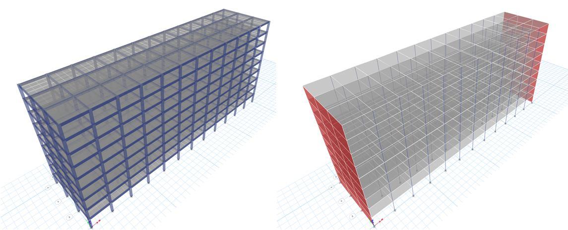
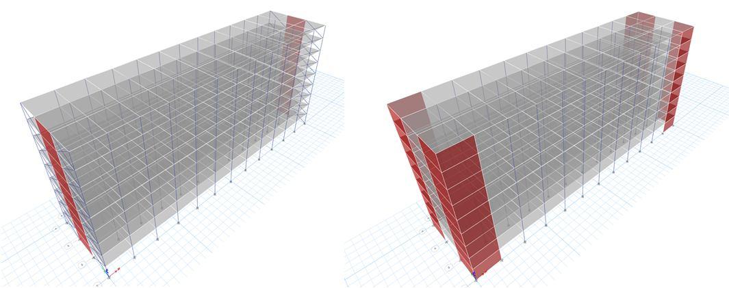
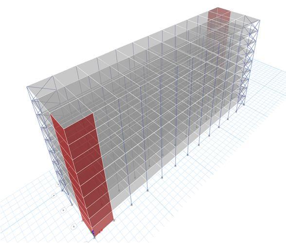
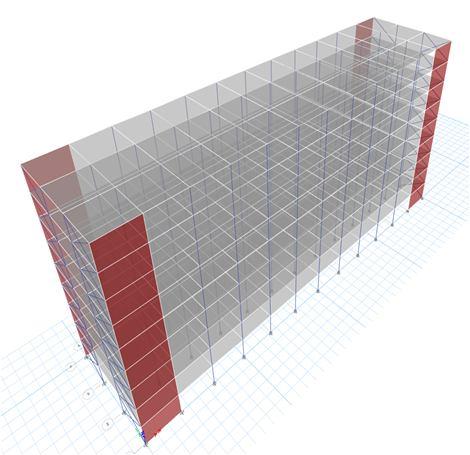
Asymmetry Model with shear wall placed at corner facing each other diagonally and bracing placed at other corner facing each other diagonally CASE 5
The built up area of asymmetry building considered here are taken equal for all different cases. The building is of size i.e., 60 m x 15 m equal to 900 m2 with a height of (G+9) Storey. The floor to floor height is taken as 3 meters for all the structures and also the section properties is also common for all case frame structures. The following below is the Case Study to be analysed and designed in this thesis
Asymmetry Model with shear wall placed at corner on same edge side parallelly and bracing placed at other corner placed on same edge side parallelly CASE 6
Asymmetry Model with shear wall on both shorter side CASE 2
Pawar, S.B. Sohani (2017) has studied that the buildings situated on hill slopes in earthquake prone areas are generally irregular, torsionally coupled & hence, susceptible to serve damage when affected by earthquake ground motion. These unsymmetrical buildings require great attention in the analysis & design. The various floors of such building steps back towards the hill slope and at the same time buildings may have setbacks also. Buildings situated in hilly areas are much more vulnerable to seismic environment. In this study, 3D analytical model of 10,15 & 20storied buildings have been generated for symmetric and asymmetric building Models and analyzed using structural analysis tool ‘STADD PRO” to study the effect of varying height of columns in ground stored due to sloping ground and the effect of shear wall at different positions during earthquake.
In this study, the equivalent dynamic analysis has been done on the different cases of regular and asymmetric cases of building frames using ETABS software. Loads considered are taken in accordance with the IS 875 (Part1 & Part2), IS 1893:2002/2016 & load combinations are according to IS 875(Part5).In this paper, the seismic analysis of asymmetry plan is been analyzed carried by Seismic Zone V using ETABS software.
Table 1 Proposed Model Cases for the Research Study
International Journal for Research in Applied Science & Engineering Technology (IJRASET) ISSN: 2321 9653; IC Value: 45.98; SJ Impact Factor: 7.538 Volume 10 Issue VIII August 2022 Available at www.ijraset.com 480©IJRASET: All Rights are Reserved | SJ Impact Factor 7.538 | ISRA Journal Impact Factor 7.894 |
Asymmetry Model with shear wall at all corners CASE 4
Asymmetry Model with shear wall at centre and X bracing at edge sides on both shorter side CASE 3
Asymmetry Model without anyretrofitting CASE 1
International Journal for Research in Applied Science & Engineering Technology (IJRASET) ISSN: 2321 9653; IC Value: 45.98; SJ Impact Factor: 7.538 Volume 10 Issue VIII August 2022 Available at www.ijraset.com 481©IJRASET: All Rights are Reserved | SJ Impact Factor 7.538 | ISRA Journal Impact Factor 7.894 | The data of structure used in this thesis is in the form of tabulation considered for design and analysis of frame are given below Table 2 Structural Specification for the study PARTICULARS STRUCTURAL PROPERTIES Total Built Up Area 60 X 15 m Number of Stories G+9 Floor to floor Height 3.0 meter Size of Columns 450X 450 mm Beam Size 230 X 450 mm Slab/Plate thickness 150 mm Shear Wall thickness 250 mm Bracing dimension 230 X 450 mm Dead load IS 875 Part 1 Live load IS 875 Part 2 Roof live load IS 875 Part 2 Earthquake load IS 1893:2016 (a) (b) (c) (d) (e) (f) Fig. 3 Three Dimensional View of All Studied Cases
International Journal for Research in Applied Science & Engineering Technology (IJRASET) ISSN: 2321 9653; IC Value: 45.98; SJ Impact Factor: 7.538 Volume 10 Issue VIII August 2022 Available at www.ijraset.com 482©IJRASET: All Rights are Reserved | SJ Impact Factor 7.538 | ISRA Journal Impact Factor 7.894 | VI. MATERIAL SPECIFICATIONS CONSIDERED FOR DESIGN & ANALYSIS OF CASES These building frames models are made up of two basic materials i.e., concrete and reinforced steel. The table given below shows the properties of materials considered for design and analysis of all RCC frame buildings. Table 3 Material Properties used in all Frames Particular Details Grade of Concrete M30 Grade of Main Steel Fe500 Grade of Secondary Steel Fe500 Beam & column cover 25 mm & 40 mm Density of Reinforced Concrete 25 KN/m3 Density of Brick walls, Plaster 18 KN/m3 Young’s modulus of steel 2 X 10 5 N/mm2 VII. LOADING SPECIFICATION & CALCULATIONS COMMON FOR ALL FRAMES USED IN SOFTWARE The loads which is to be studied in the project is discussed under following clauses below in which their calculation detail is also been discussed such as Primary load, Seismic Load & their load combination etc. A. Primary Loads Applied for Analysis In Software, the loads are taken in the form of load cases i.e. primary load cases and the load combination of primary load cases also which are used same for all frame buildings. Firstly, here are the primary load cases which have been used in ETABS software analysis are given below in table 3.4 with their load type & numbers Table 4 Primary Load Cases Load Case Number Load Type Name 1 Dead Load DL 2 Live Load LL 3 Seismic Dynamic Load DQX 4 Seismic Dynamic Load DQY B. Load Calculations Used for All Frame Cases The calculated load acting on the structures of dead load, floor live load, roof live load is given below 1) Dead Load (D.L): In this analysis, dead load includes dead load of the slab, dead load of beam & column, dead load of external walls and dead of internal walls. DEAD LOAD is designated as D.L in ETABS. # Self Weight of Slab/Plate = (unit weight of concrete X thickness of slab) = 25 X 0.15 = 3.75 KN/m2 # Self Weight of Column (0.45x0.45) = = (unit weight of concrete X size of column) = (25 X 0.45X 0.45) = 5.0625 KN/m (per meter height) # Self Weight of Beam in all floors = = (unit weight of concrete X depth of beam X width of beam) = 25 X 0.45 X 0.23 = 2.5875 KN/m
and further collected and compared with all the cases shown below Graph 1 Comparison of Maximum Displacement Along X Direction Graph 2 Comparison of Maximum Displacement Along Y Direction 9080706050403020100 Storey9 Storey8 Storey7 Storey6 Storey5 Storey4 Storey3 Storey2 Storey1 mm)(in Storey CASE 1 CASE 2 CASE 3 CASE 4 CASE 5 CASE 6 80706050403020100 Storey9 Storey8 Storey7 Storey6 Storey5 Storey4 Storey3 Storey2 Storey1 mmin CASE 1 CASE 2 CASE 3 CASE 4 CASE 5 CASE 6
VIII. RESULT & DISCUSSIONS The reports for the analysis is been exported from the
International Journal for Research in Applied Science & Engineering Technology (IJRASET) ISSN: 2321 9653; IC Value: 45.98; SJ Impact Factor: 7.538 Volume 10 Issue VIII August 2022 Available at www.ijraset.com 483©IJRASET: All Rights are Reserved | SJ Impact Factor 7.538 | ISRA Journal Impact Factor 7.894 |
3) Earthquake or Seismic Load (EQX & EQZ): Earthquake load or seismic load calculation involves the full dead load plus the percentage of live or imposed load as per IS 1893:2016 considerations and importantly for calculating earthquake or seismic load. Also, as per IS 1893 Seismic weight of each floor is its full dead load plus approximate amount of live or imposed load. In this study, the approximate amount of live or imposed load considered is 50% of the total live load as per IS 1893 (Table 8) and all the rest calculation is done with the help of ETABS Software. SEISMIC OR EARTHQUAKE LOAD is designated as DQX & DQY where “DQ” stands for Dynamic Earthquake load whereas X & Y represents their respective lateral direction. modelling,
2) Live Load (L.L): In this research, live load includes live load for all the floors as it is considered from the commercial building category given in IS 875 Part 1 and live load for roof is also considered from same above code. LIVE LOAD is designated as L.L. and ROOF LIVE LOAD is designated as R.L.L in ETABS. Here we consider Live load for all the floors = 5 KN/m2 Live load for roof (at Terrace) = 1.5 KN/m2
International Journal for Research in Applied Science & Engineering Technology (IJRASET)
484©IJRASET:
IX.
[4] Dr. S. A. Halkude, Mr. M. G. Kalyanshetti, Mr. V. D. Ingle, “Seismic Analysis of Buildings Resting on Sloping Ground with Varying Number of Bays and Hill Slopes”, International Journal of Engineering Research & Technology (IJERT) , ISSN: 2278 0181, Vol. 2 Issue 12, December 2013.
[5] IS: 875 (Part I) 1987, “Code of Practice for Design Loads (Other than Earthquake) For Buildings and Structures”, Part 1 Dead Loads Unit Weights Of Building Materials And Stored Materials, Second Revision, September 2003.
[6] Miss. Pratiksha Thombre, Dr.S.G.Makarande, “Seismic Analysis of Building Resting on Sloping Ground”, Journal of Emerging Technologies and Innovative Research (JETIR) ISSN 2349 5162, Volume 3, Issue 6 , June 2016.
[7] Sujit Kumar, Dr. Vivek Garg , “Effect Of Sloping Ground On Structural Performance Of Rcc Building Under Seismic Load”, International Journal Of Science, Engineering And Technology (IJSET), ISSN: 2348 4098, Volume 2 Issue 6 August 2014.
1) It is been concluded that the displacement of asymmetric building with no retrofitting shows maximum value along both the lateral direction which is approximately 38.8 % more than Case 2 model having shear wall at all high stress concentrated portion.
ISSN: 2321 9653; IC Value: 45.98; SJ Impact Factor: 7.538 Volume 10 Issue VIII August 2022 Available at www.ijraset.com All Rights are Reserved | SJ Impact Factor 7.538 | Journal Impact Factor 7.894 | CONCLUSIONS
[3] Nagarjuna, Shivakumar B. Pati “Lateral Stability of Multi storey Building On Sloping Ground”, International Research Journal of Engineering and Technology (IRJET) e ISSN: 2395 0056, Volume: 02, Issue: 04, July 2015.
2) Case 3 model have displacement value 34.8% more than Case 4 model. Since, the shear wall is center making more stiffer structure along Y direction.
[8] IS: 875 (Part 2) 1987, “Code Of Practice For Design Loads (Other Than Earthquake) For Buildings And Structures”, Part 2 Imposed Loads, Second Revision and June 1998.
The following conclusions were made from the investigation
3) The least displacement is shown by case 4 i.e., 44 mm along Y direction and case 2 shows 19 mm along X direction having shear wall along short side which was previously 78 mm without shear wall.
ISRA
[1] Rahul Manojsingh , Pawar, S.B. Sohan, “Analysis Of Set Back Step Back Building resting On Sloping Ground”, Journal of Emerging Technologies and Innovative Research (JETIR) , ISSN 2349 5162, Volume 4, Issue 06 ,June 2017.
REFERENCES
[2] Krishna Kumar, Sristi Gupta, Shivam Kumari “Dynamic Study Of Step Back And Set Back Building”, International Journal of Civil Engineering and Technology (IJCIET) , Volume 9, Issue 5, May 2018, pp. 185 190.