
10 X October 2022 https://doi.org/10.22214/ijraset.2022.47087
ISSN: 2321 9653; IC Value: 45.98; SJ Impact Factor: 7.538

Volume 10 Issue X Oct 2022 Available at www.ijraset.com

ISSN: 2321 9653; IC Value: 45.98; SJ Impact Factor: 7.538
Volume 10 Issue X Oct 2022 Available at www.ijraset.com
Sundram1, Rahul Kumar2 1, 2Department of Mechanical Engineering, C.V Raman Global University
Abstract: In this project “Aerofoil Design and Analysis” an attempt has made to make a complete study on lift and drag coefficient of various aerofoil sections using CFD. The primary goal of this project is to learn and analyse the aerodynamic performance of wings. The objective of this study is to improve aerofoil design using the software CATIA, And Fluent Analysis using the software ANSYS. Aerofoil is a principal part of any airplane construction. How much lift force and drag force is sufficient to balance the weight of the plane is decided by the aerofoil. Aerofoils are basically divided into two categories - they are Asymmetrical and Symmetrical aerofoils. Based on their drag and lift coefficient’s variation with angle of attack, stall angle of attack and magnitude of the coefficients they are divided. Here the NACA aerofoil is modified by adding dimples on the upper half of the wing and compared with the simple one. The comparison is made on different speed and pressure on the wing and the coefficient of lift and drag.
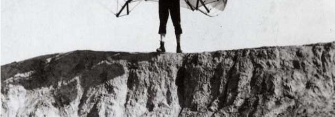
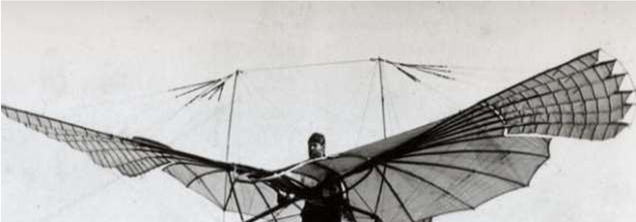
The only means of locomotion in the beginning, when man was still living in the lap of nature, was his legs. We have gradually progressed to speedier and more opulent modes of transportation, the most recent of which being air travel. As the aeroplanes were developed, they gained far more popularity than any other long distance travelling vehicle because it was the fastest way to travel and transport available. This led to rapid discovery in air transport field, to get the best out of the aerodynamics of the plane to conserve fuel and make it faster or whatever the need be. All of this is achieved by modifications made in the aerofoil design which with our project we aim to achieve. The legendary Wright brothers conducted some of the first study on the curvatures or camber of a wing, known as an airfoil.

Airfoils were originally hand built for each aircraft while powered flight was yet in its infancy. Prior to World War I, there was no standardised airfoil that could be used on a variety of planes,and few individuals were working on developing one. The British government had previously done some study at the National Physical Laboratory (NPL), which resulted in a series of Royal Aircraft Factory airfoils.
ISSN: 2321 9653; IC Value: 45.98; SJ Impact Factor: 7.538 Volume 10 Issue X Oct 2022 Available at www.ijraset.com
Since World War II, it has also developed a reputation as a war machine. This increased popularity of air travel has resulted in numerous new inventions and research projects aimed at developing faster and more cost effective planes. This endeavour is an attempt to figure out how to get the most performance out of a segment of an airfoil.
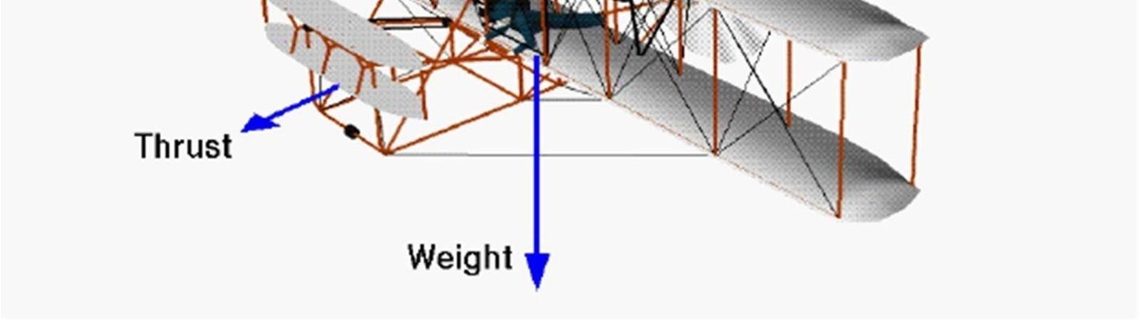
Figure 2. force components of wright 1903 flyers. (Source. NASA)
A cross section of a plane's wing is referred to as an airfoil. Its primary function is to give an aeroplane lift during take off and flight. However, it has a side effect known as drag, which works against the plane's velocity. The amount of lift a plane requires is determined by its intended function. Lift is required by heavier planes, whereas lightweight planes require less.As a result, the airfoil section is calculated based on the aircraft's use. The plane's vertical acceleration is also determined by the lift force, which is determined by the plane's horizontal velocity. With all other factors being equal, faster moving air has lower pressure than slower moving air, according to Bernoulli's principle, stated by Daniele Bernoulli, one of the most important pioneers in the field of fluid dynamics. This difference is what allows the slower moving air to push up against the bottom of the wing with greater force than the faster moving air is pushing down against the top of the wing. In level flight, this upward force is just enough to counteract the downward force caused by gravity.

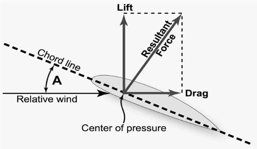
The force acting on the airfoil, perpendicular to the direction of the flow is defined as a lift force. The force acting on the airfoil, parallel to the direction of the flow is defined as a drag force. Dimensional analysis reveals that the nondimensional coefficients depends on the angle of attack, the Reynolds number, the Mach number and on the airfoil shape.
L, D = ( , , ∞, ℎ )
Figure 3. force on airfoils. (source. perfectedflight)
ISSN: 2321 9653; IC Value: 45.98; SJ Impact Factor: 7.538
Volume 10 Issue X Oct 2022 Available at www.ijraset.com
The National Advisory Committee for Aeronautics (NACA) a US based committee became a pioneer in the field of aerodynamics engineering, they created airfoil forms for aircraft wings (NACA). Following the word "NACA," a series of numerals explain the shape of the NACA airfoils. NACA initially developed the numbered airfoil system which was further refined by the United States Air Force at Langley Research Centre.

The numerical code's parameters can be placed into equations to exactly construct the airfoils cross section and calculate its properties. Even now, some aircraft still use NACA four digit and five digit airfoil sections created in the 1930s and 1940s.
E. NACA 642 415
Where,
1) “NACA” stands for National Advisory Committee for Aeronautics.
2) “6”denotes the Series designation.
3) “4”denotes the chordwise position of minimum pressure in tenths of the chordbehind the leading edge for the basic symmetrical section at zero lift.
4) The subscript “2” indicates the range of lift coefficient in tenths above and below thedesign lift coefficient in which favourable pressure gradient exist on both surfaces.
5) “4” following the dash denotes the design lift coefficient in tenths.
6) The final two digits “15” denotes airfoil thickness in percent of the chord (15%).
We are using Ansys for the analysis purposes. It offers structural analysis software solutions that enable engineers of all levels and backgrounds to solve complex structural engineering problems faster and more efficiently. With their suite of tools, we can perform finite element analyses (FEA), customize and automate solutions for structural mechanics challenges and analyse multiple design scenarios. By using Ansys early in the design cycle, businesses can save costs, reduce the number of design cycles and bring products to market faster.
ISSN: 2321 9653; IC Value: 45.98; SJ Impact Factor: 7.538
Volume 10 Issue X Oct 2022 Available at www.ijraset.com
Catia is used for designing the components that are being utilised in the project. CATIA is the world's most popular engineering and design software for 3D CAD product design. It is usedin a range of industries to design, simulate, analyse, and create items, including aerospace, automotive, consumer goods, and industrial machinery, to mention a few.
An aerofoil is a phrase used to describe the cross sectional shape of an object that provides an aerodynamic force when propelled through a fluid such as air. Aerofoils are used on aeroplanes as wings or propeller blades to provide lift and propulsion. Both of these forces are generatedin the opposite direction of the air flow. Drag occurs as a result of the formation of lift/thrust and acts in the same direction as the airflow.
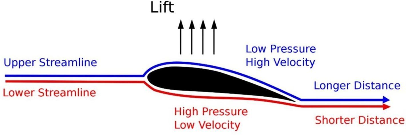
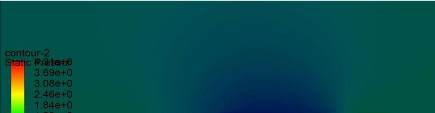
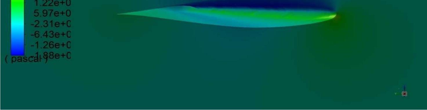
Bernoulli’s theorem describes the fundamental principle of an aerofoil. Basically, total pressure equals static pressure + dynamic pressure (due to the weight of air above) (due to the motionof air).
When air passes over the top surface of an aerofoil, it has to travel quicker, gaining dynamic pressure in the process. The loss of static pressure causes a pressure difference between the upper and lower surfaces, which is known as lift and works against an aircraft's weight (or thrust that opposes drag).
More lift is provided by increasing the angle of attack (the angle between the chord line andthe relative air flow). The aerofoil will stall when it reaches the crucial angle of attack (usually approximately 14 degrees).
A second method crosses the streamlines using Euler's Equations (from which the Bernoulli equation is derived). The higher velocity and acceleration over the top of the wing need a lower pressure above the wing than the ambient pressure due to the curve of the wing.
The path that a fluid molecule takes is known as a streamline. The fluid velocity is parallel to every point along the streamline. It may thus be demonstrated that the pressure below the wing is greater than the pressure above the wing using either of the two ways. The difference in pressure causes an upward lifting force on the wing, allowing the plane to fly.
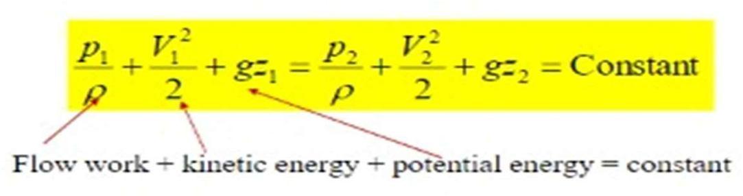
Bernoulli equation applied along a streamline : …
Where,
P: Pressure of the fluid.p: Density.
v: Velocity of the fluid relative to the airfoil.g: Magnitude of acceleration.
z: Height of the point.
ISSN: 2321 9653; IC Value: 45.98; SJ Impact Factor: 7.538 Volume 10 Issue X Oct 2022 Available at www.ijraset.com
Take point 1 to be well in front of the wing on the streamline P1 = P ambient is the pressure here. Take point 2 to be outside the boundary layer, above the curved surface of the wing. gz1 and gz2 are believed to be insignificant in comparison to the other elements of the equation (i.e., the effects due to gravity are small compared to the effects due to kinematics and pressure).
The equation then is: Take point 1 to be at a location on the streamline in front of the wing in the second example. The constant from Equation 2 is assumed to be the same because the values for P ambient and V ambient are the same as in the first example. Consider point 2 to be below the wing and outside of the boundary layer.
The equation becomes:
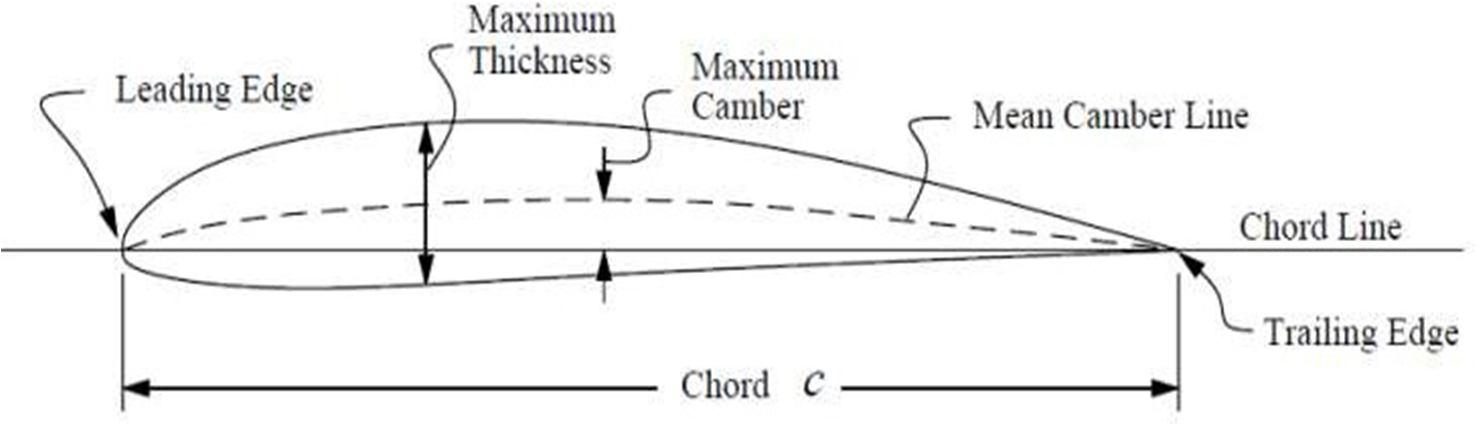
There are a number of terms involved while dealing with aerofoils:
1) Leading Edge: Forward edge of the aerofoil
2) Trailing Edge: Rear edge of the aerofoil.
3) Chord: The line joining the leading and trailing edge. It gives the length of the aerofoil.
4) Mean Camber Line: Line drawn half way in between upper and lower surface of theaerofoil. It gives the amount of curvature of the wing.
5) Point of Maximum Thickness: it is the thickest part of the wing given as a percentageof the chord. The designer can vary the performance of an aerofoil by changing each of the above aspects sothat it is appropriate for the task at hand.
In this project an effort has been made to have a detailed study and modification on lift and drag coefficient of various Airfoil section. We tried to differentiate between the two types i.e. Symmetrical and Asymmetrical Airfoil on the basis of their lift and drag coefficient, Variation with angle of contact, stall angle of attack and magnitude of the coefficients. Modelling of Symmetrical and Asymmetrical Airfoil in ANSYS has been studied, also the lift force on various foil on each angle of attack is determined and the horizontal velocity required for vertical acceleration during take off for the foil has been calculated.
Due to the rise and availability of fuel and construction cost, transportation cost is increasing day by day in all modes. Airways have become more efficient mode of transportation today, this motivated us to study the design of airfoil and modification of few airfoil has been carried out so as to enhance the lift force and reduce the drag coefficient which would result in increasing the efficiency of aeroplanes and simultaneously reducing the fuel cost, which would lead to a major saving in construction cost of runways i.e., with small runway a flight with our designed airfoil can take off more easily and efficiently.
"Control Theory based airfoil design using Euler's equations", a paper describing theoptimising techniques based on the control theory for airfoil design. Results are presented forboth the inverse problem and drag minimisation [1] “An Investigation of the effect of aspectratio on Airfoil performance.” Describing the effect of aspect ratio on the overall performanceof airfoil.[2] This paper deals with the changes in shapes with respect to the changing of coordinates [3] They investigated and presented the creation of an airfoil profile in a CADenvironment using the control purpose of the camber profile in the article. The state of theprofile could be effectively changed using a method for modifying the quality of controlfocuses. The shape of the cambered airfoil was formed without affecting the fundamentalgeometry of the airfoil.[4] The NACA 4412 airfoil profile was investigated and its usefulnessfor wind turbine edge investigation was discovered. GAMBIT 2.4.6 is used to form the geometry.[5]
ISSN: 2321 9653; IC Value: 45.98; SJ Impact Factor: 7.538 Volume 10 Issue X Oct 2022 Available at www.ijraset.com
Using Quansi 3D analysis codes, devised a method for optimising TurbineAirfoil. He overcame the difficulty of 3D modelling by modelling numerous 2D airfoil sections and combining their figures in a radial manner with second order polygons.[6] Providing indepth study of three airfoils namely RAE2822, ONERA M6 (D section) and NACA4412 .Thefindings reveal the rate at which aerodynamic properties converge in relation to geometricdesign factors, implying that geometric tolerance may not always be adequate to ensureconvergence of certain parameters.[7] Its show that the pleated corrugated aerofoil produces acomparable higher lift coefficient then that of Profiled aerofoil NACA 0012. The lift to dragratio of these aerofoil is higher in between 4 to 8 degrees and it also has highest gliding ratiocompared to the traditional aerofoil NACA 0012. The conclusion shows that the performanceparameters of the bio mimicked corrugated dragonfly wing is better than NACA 0012.[8] This study presents the optimization of better and efficient aerofoil in wing design of eagle sized flapping wing aircraft, Which will also capable of Hovering flight. And it is proved thatfor an angle of attack of 0 degrees, with a maximum lift coefficient of 0.542 and a dragcoefficient of 0.005 is good enough, for low speed long range operational flapping aircraft.Also, it needed a very good lift and drag ratio for efficient and predictive aerofoil for thisflapping wing Aircraft.[9] This paper presents both the Aerodynamic design and optimizationof the Natural Laminar Flow (NLF) wing and the high lift configuration considering the mutualeffects of both flap devices. And it is Proved that use of NLF technology at cruise design pointleads to a reduction of 40 drag counts with respect to the turbulent aircraft. Also, some extra gains could be obtained by the Optimization of the wing tip device. Also, it has been observed the use of the droop nose increases significantly the stall margin and improves the dragcoefficient while take off condition.[10] The identification of the modal properties which arethe mode shaped and the corresponding natural frequencies of the aircraft wing structure was measured. Here they compared for two different materials applied towards the wing structures which are the aluminium alloy AA 7075 T6 and AA 2024 T3 which currently being widely used by the aircrafts. And it is verified that both suitable to be used in building the wing structures as both do have alike properties but in term of strength levels, AA 7075 T6 are quite higher compared to AA 2024 T3. Natural frequencies for AA 7075 T6 were much lower compared to AA 2024 T3 which make AA7075 T6 much more suitable material for aircraft wing structure.[11] This presents the difference between Asymmetrical and symmetrical aerofoil. And proved that symmetrical aerofoil has nearly equal drag coefficient as of asymmetrical aerofoil for same length and camber of aerofoil. Also, Asymmetrical have higher lift coefficient.[12] Simulation based experiment given result of pressure distribution, Coefficient of drag, coefficient of lift, lift to drag ratio, vector profile and wake generation.[13] They designed the standard NACA 0015 in ANSYS design modeler and further modified by adding dimple and a gurney flap at the lower end of the airfoil sheet. Then analysed the resultby changing the dimensions of the modification. Research was done at various angles of attack from 0˚ to 20˚ at two different chordal Reynolds, Rec = 2.5 x 10⁵ and 3.6 x 10⁵. The torque coefficient is finally improved by an optimized use of the Gurney flap and the semi circular dimple.[14] Selection of wing parameters. Considerations for choice of wing parameters airfoil section, aspect ratio, sweep, taper ratio, twist, incidence, dihedral and vertical location.[15] The major goal of this study is to investigate and analyse the aerodynamic effects of dimples on the horizontal axis wind turbine blade's surface. When dimples are added to the blade surface of a wind turbine its efficiency improves.[16]
The properties of airfoil lift, drag, and stall caused by flow separation were examined in this study. Keep in mind that airfoils aren't just for aeroplanes. The research described here can be applied to a variety of fluid dynamics scenarios: F1 car wings, helicopter blades, propeller blades, hydrofoils, and wind turbine blades. Turbine blades are an illustration of this.[17] Published on 1 September 2004. This paper presents a study on parameterization methods for airfoil shape optimization within a CAD based design framework. The objective of the paperis to study the effect of different methods on airfoil shape optimization when using computational fluid dynamics (CFD). Two airfoils are studied in this paper to analyse their flexibility and robustness in producing optimal shapes when used in optimization study.[18]
The investigation on albatross a huge sea bird finding out how they use dynamic soaring by removing power from the vertical wind speed gradient. These birds take advantage of wind gradient which are formed due to interaction amid air and sea to fly thousands of kilometres without beating of wings. Lift coefficient of E423 was best in comparison with E420 E421 and E422. Lift coefficient of GOE 174 was found higher than GOE 176 and E423 from minus 12to plus 10 degree AOA. The result shows that the albatross wing performs better than delta wing, rectangular wing and Albatross wing.[19] It states investigation performed on NACA 0012 airfoil to analyse the effect of variation on Reynold’s number on airfoil with and without gurney flap. Lift decreases and drag increases when Reynolds number is decreased. For high Reynold’s number above critical range decrease in CL & increase in CB are negligible. For lower Reynold’s number the two vertices behind the GF seems to increase the effective camber of the airfoil, causing zero lift angle and reduced stall angle.[20] It describes how we can improve the efficiency and reliability of a turbine. We can use CFD for this.
ISSN: 2321 9653; IC Value: 45.98; SJ Impact Factor: 7.538 Volume 10 Issue X Oct 2022 Available at www.ijraset.com
A lift driven vertical axis wind turbine generates peak power when it is rotating at high tip speed ratios. At this blade encounter angle of attack over small range from 0 degree to 30 degree. Its ability of self start is dependent upon its performance at low tip speed ratio during which angle of attack is between 0 degree to 180 degree. The result obtained from CFD model show reduction in coefficient of tangential force at low angle of attack (less than 90 degree) of no more than 30%while at high angle of attack an improvement of tangential force of over 100% is observed.[21] It tells the need to enhance the aerodynamic of any windy shapes. The lift and drag forces at various angle of attack of a NACA 0015 blade were investigated in a wind tunnel.The test section was 1.2 m x 2.4 m depth. The maximum wind speed is 25m/s dimensions of normal blade are 0.7m length and 0.2m chord. Dimensions of studied blade are 700mm span and a 195mm chord. The aerodynamic of the span wise NACA0015 aerofoil blades with and without wavy leading edge design were examined under steady and unsteady wind conditions, with wavy leading edge blades can generate a better lift.[22] This paper present design and development of front and rear wings for an existing FSAE prototype which can generate adown force of 25 to 30 kg. Based on motorsport racing aerodynamic requirement, aerofoil S1223 was selected. At Re 1.84X 10⁵ , down force of 34.8kg and drag force of 8.317kgf was generated.[23] In this paper, the shape design optimisation using morphing aerofoil/wing techniques, namely the leading and/or trailing edge deformation of a natural laminar flow RAE 5243 aerofoil is investigated. The use of morphing technique; LTED on an existing aerofoil, can reduce significantly the transonic drag which will save operating and manufacturing cost as well as emission reduction.[24]
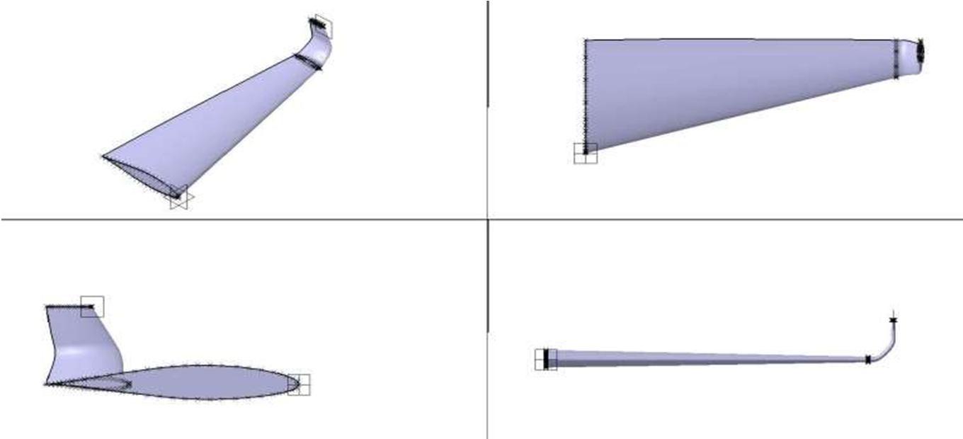
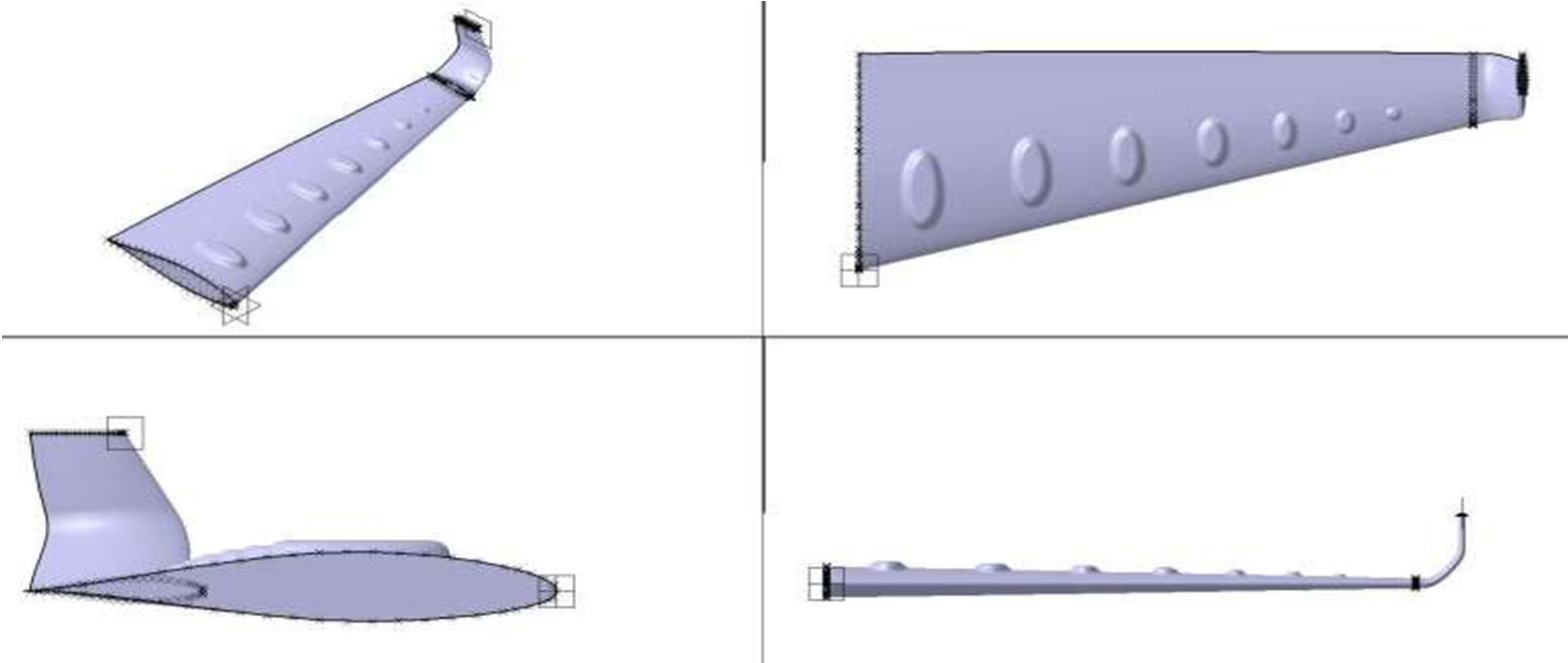
In this new generation any physical problem is first analysed virtually. Then the prototype is made to test after the successful result in both, the actual model is built. There is many software available for modelling a 3D design and in our project, we have used Catia V5 to model this airfoil. For the design of the profile of the airfoil the coordinates of the Standard NACA 64215 are imported from the official website of the NACA Airfoil tool, which is used to plot the profileof the airfoil. The starting point of the Airfoil is of 100mm chord length. The airfoil is tapered from one side and the profile is reduced to 33mm chord length. Because the previous surveyof few researchers shows that the tapered wings have high lift coefficient and better efficiency. And the efficiency could also be increased by adding the winglets.
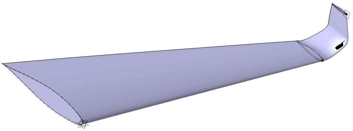
Figure 7. plane airfoil with winglets.
The profile of the 18mm chord length and perpendicular to the horizontal plane at a distanceof 30 mm is generated and connected to the airfoil with the corner radius of 10mm.
Figure 8. crossectional view of plane airfoil.
ISSN: 2321 9653; IC Value: 45.98; SJ Impact Factor: 7.538
Volume 10 Issue X Oct 2022 Available at www.ijraset.com
The air drag is the limitation and on the large surface area of the airfoil the drag is also high,so to reduce the air drag the dimple is generated on the top surface of the airfoil to improve the bounding flow separation by generating vortex.
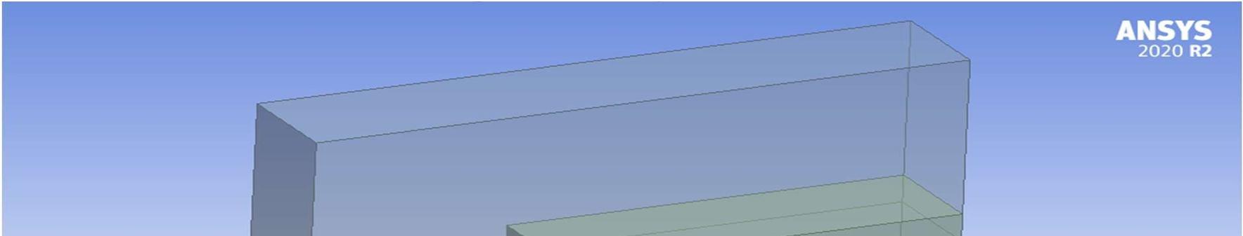
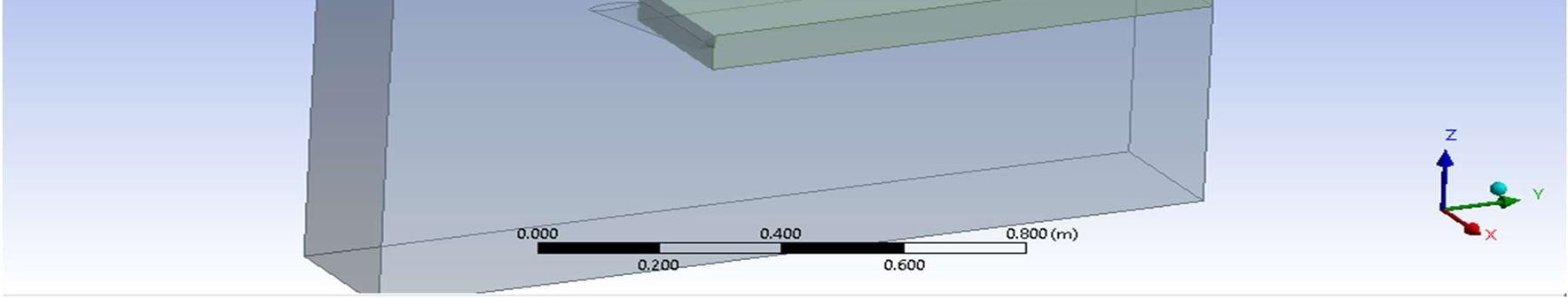
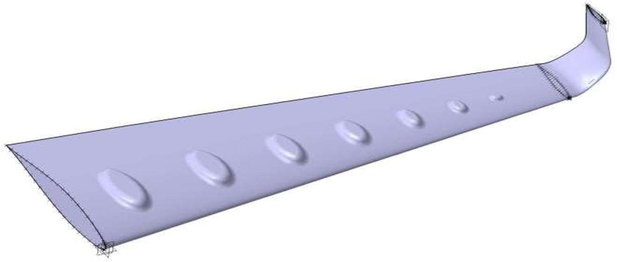
Figure 9. modified airfoil with dimples.
The dimple is added at 33% of the chord length which is equally spaced.
Figure 10. crossectional view of modified airfoil.
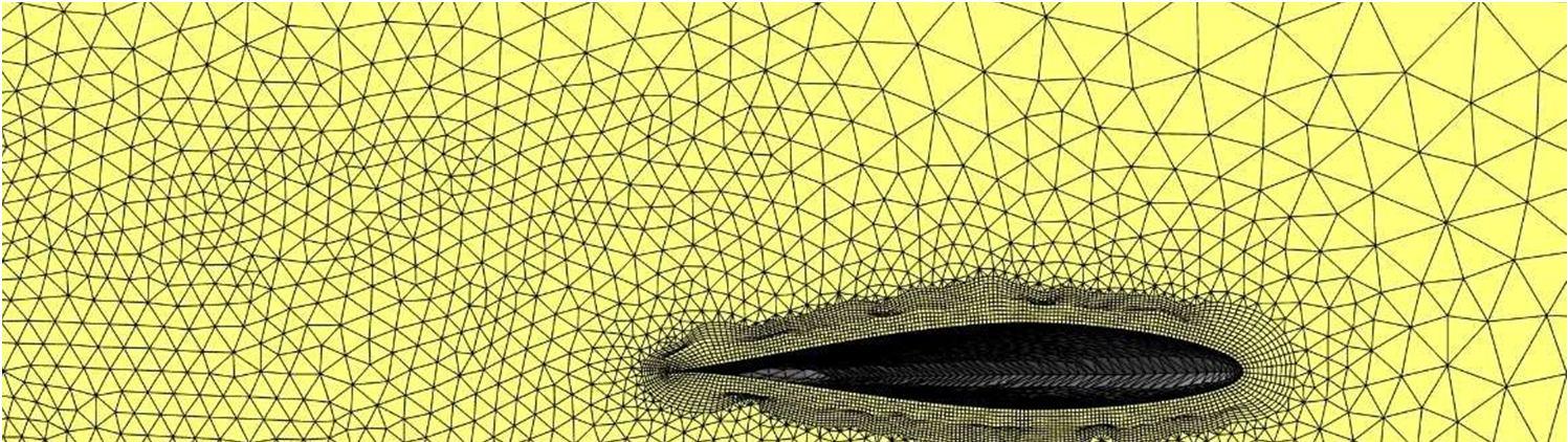
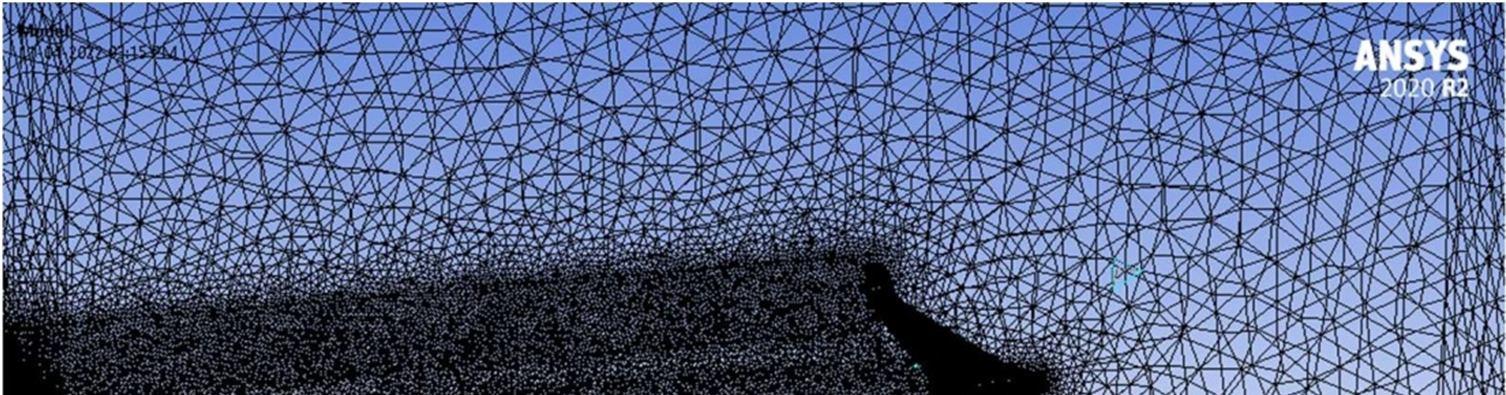
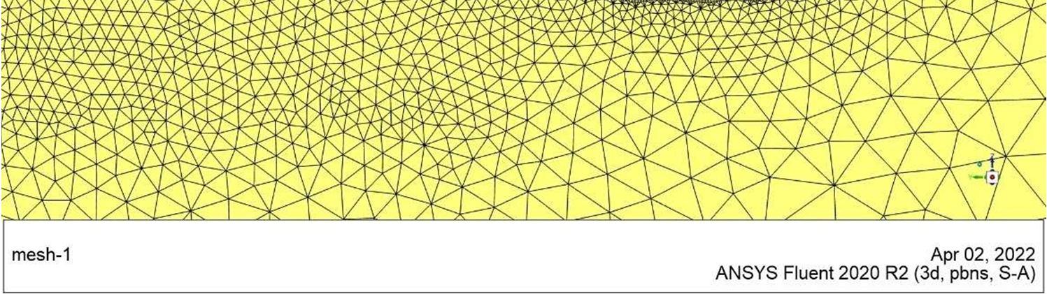
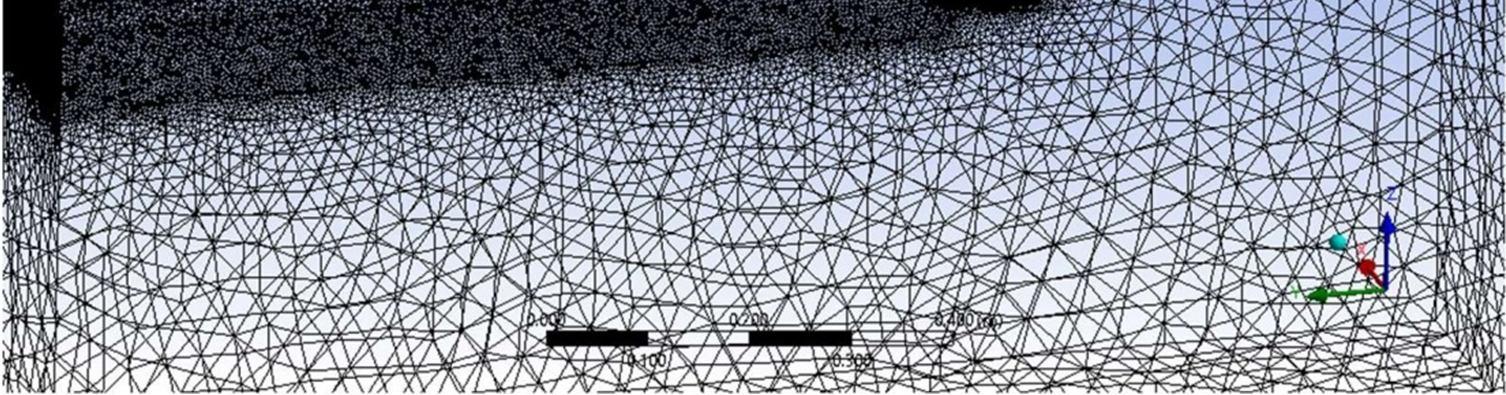
The analysis is done in a rectangular domain with a length of 150cm, breadth of 100cm, and width of 28cm. The meshing is generated unistructural tetrahedral mesh because of its ability to mesh easily for complex geometry and arbitrary position. To make the mesh finer, the edge sizing is done, and the airfoil face sizing is done. To measure the exit flow finer mesh is generated at the tip of the airfoil in a rectangular domain and meshed to size of 0.004m taking it as the body of influence.
Figure 11 control volume
ISSN: 2321 9653; IC Value: 45.98; SJ Impact Factor: 7.538 Volume 10 Issue X Oct 2022 Available at www.ijraset.com
Table 1: Mesh properties
Element size 0.04 m
No division in edge sizing 150
Element size on face 0.005 m
No of Inflation layer 12
Growth rate 1.2
Total thickness 0.04 m
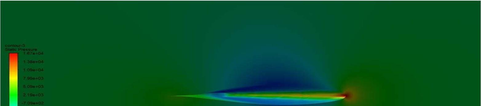
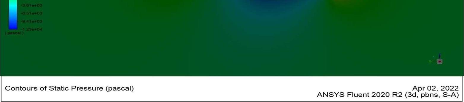
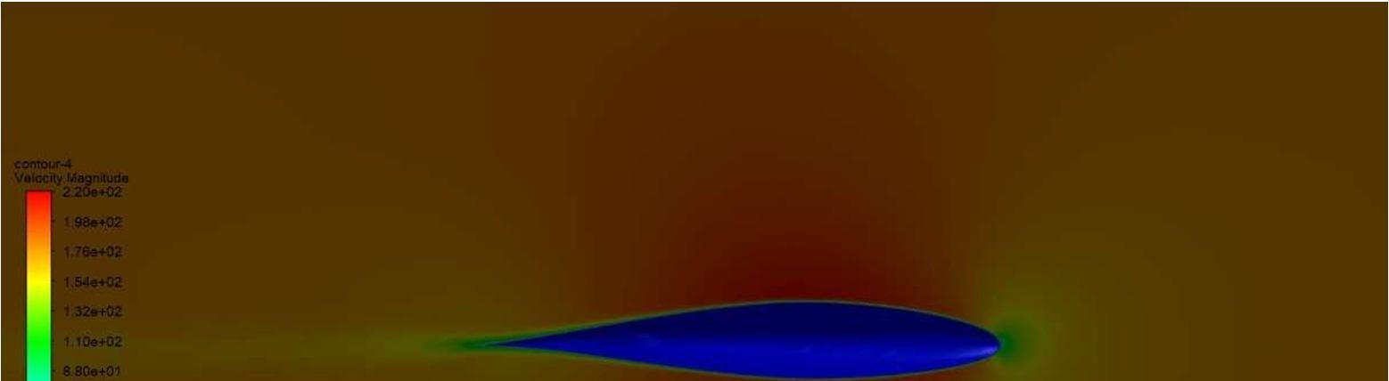
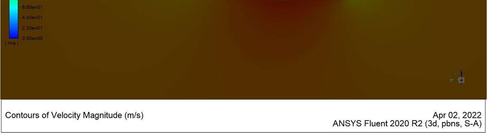
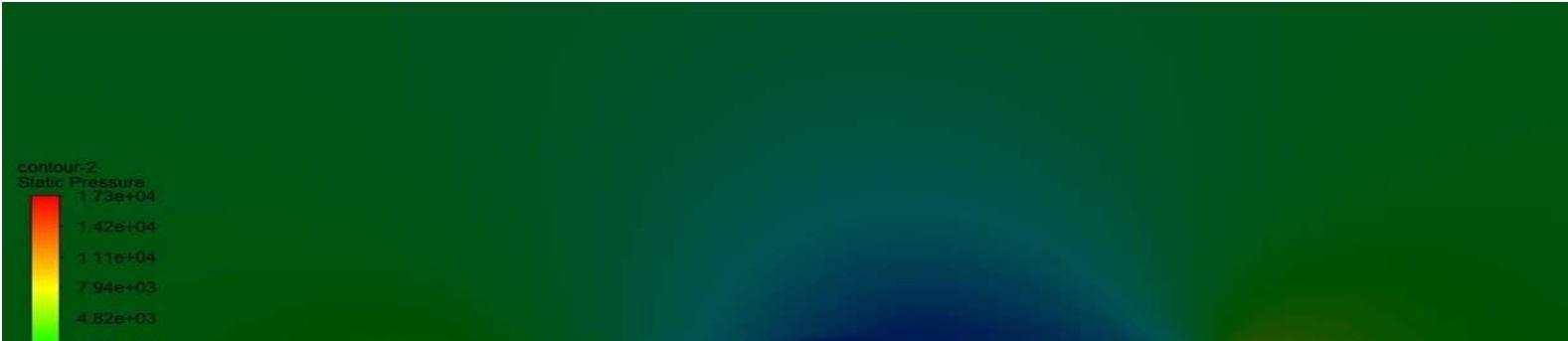
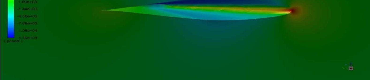
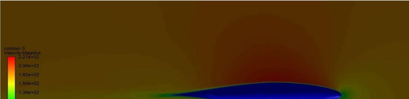
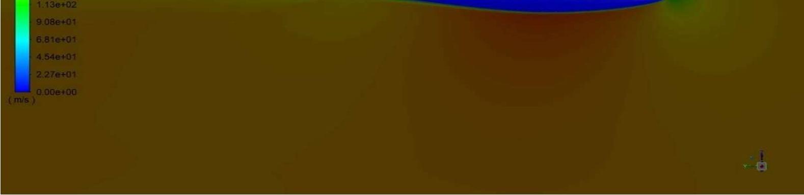
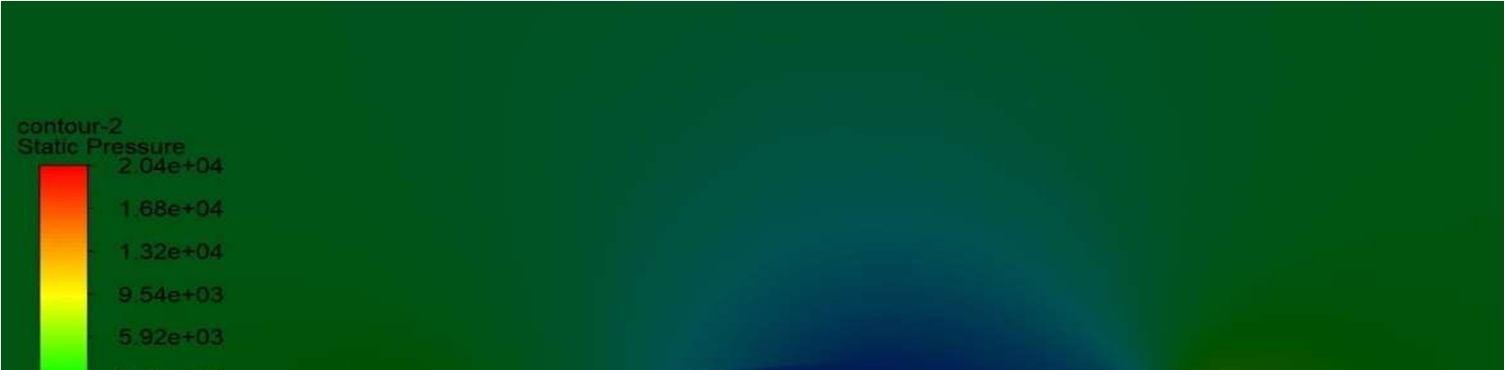
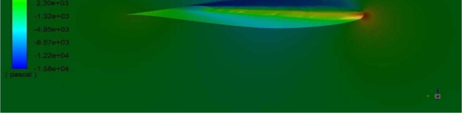
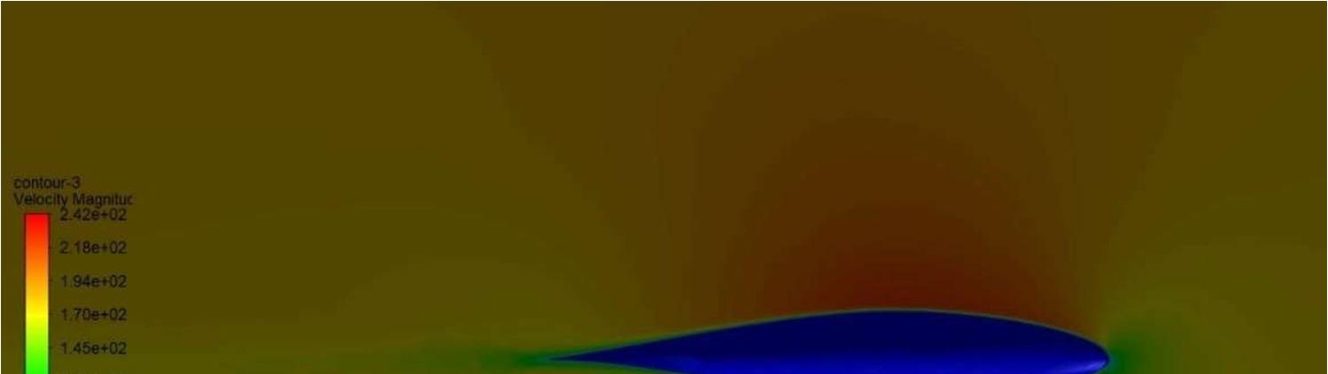
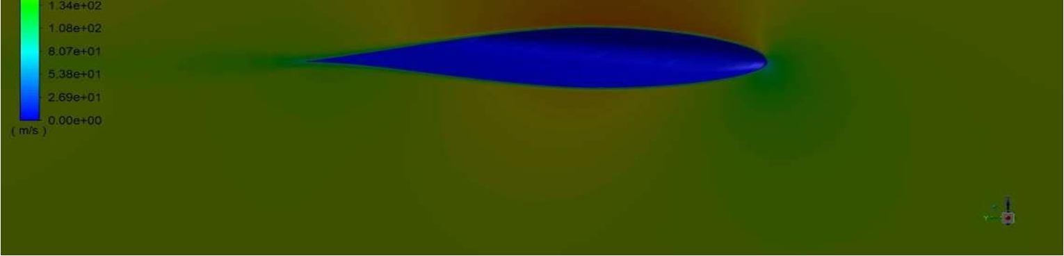
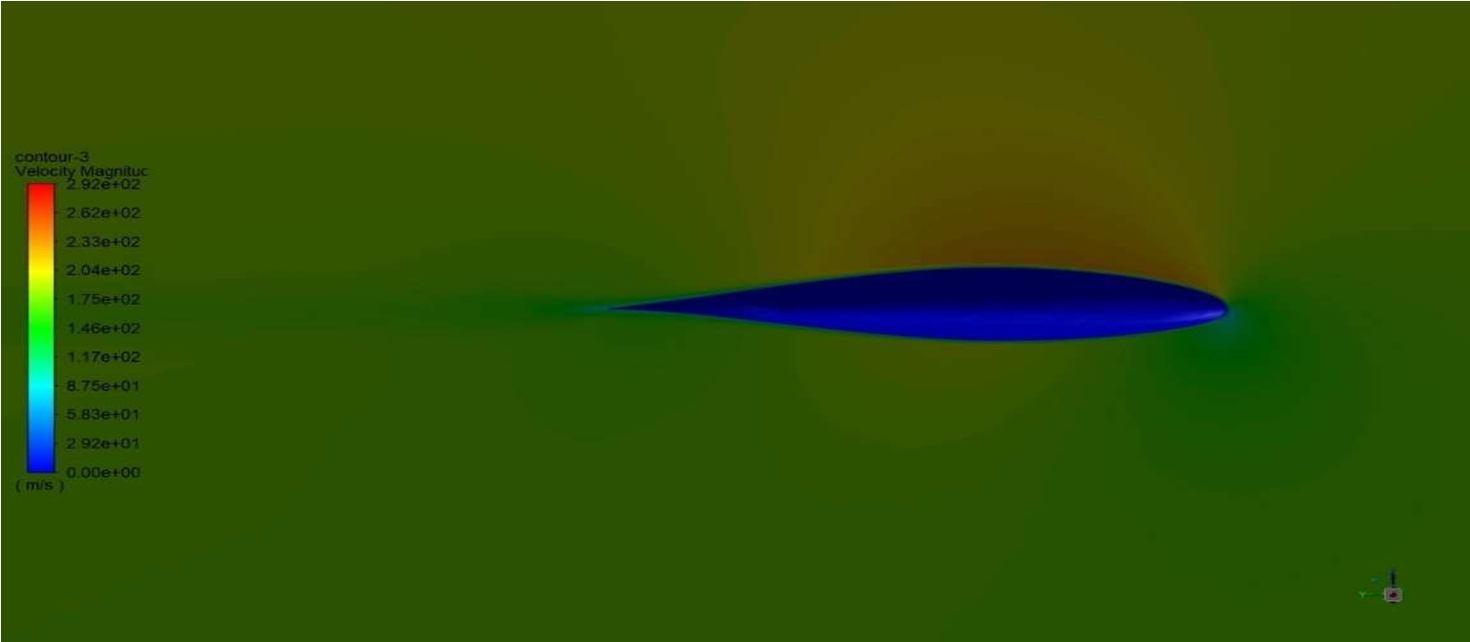
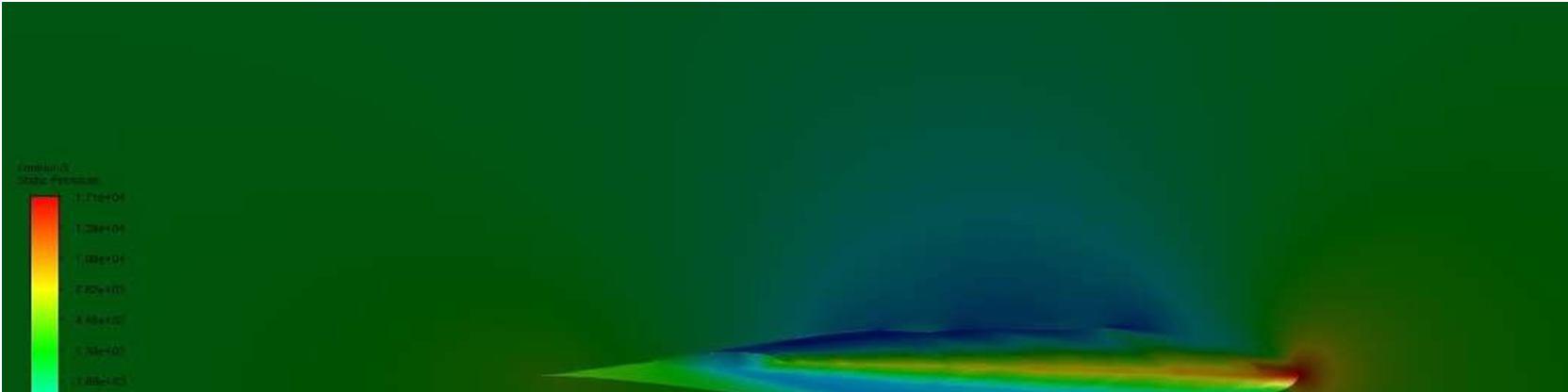
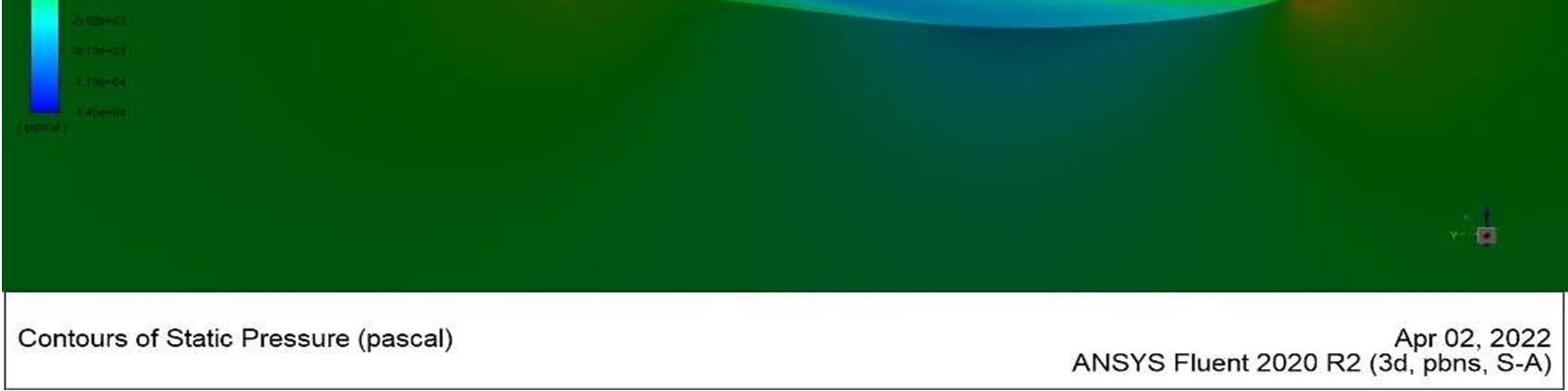
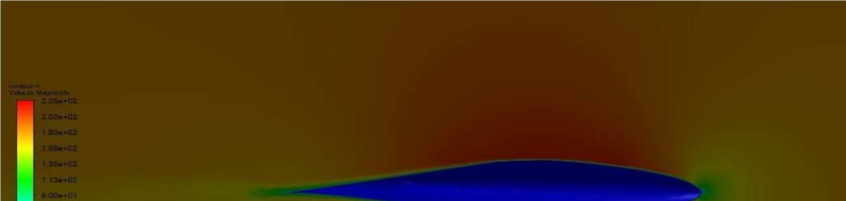
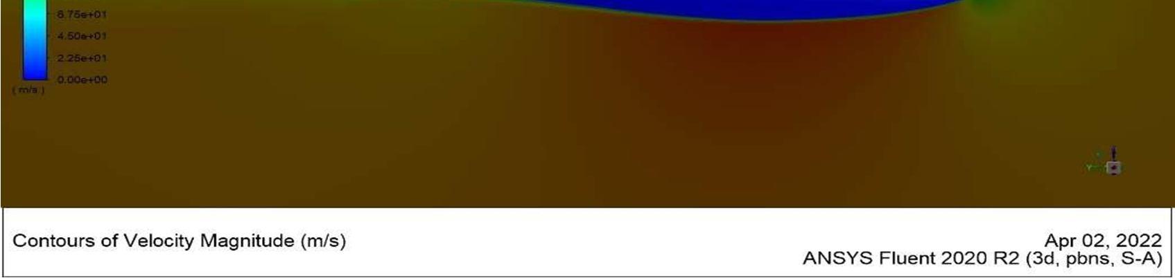
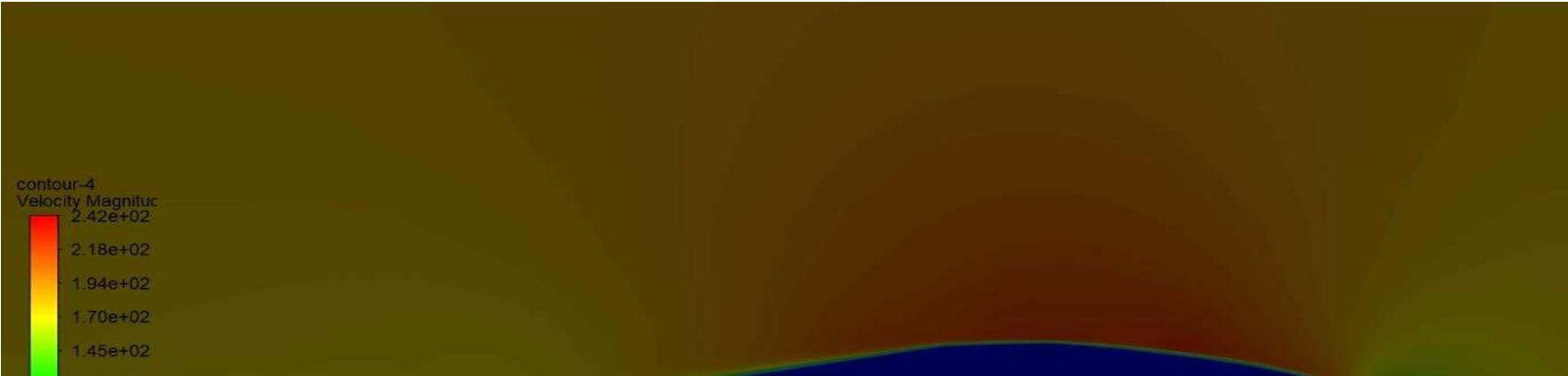
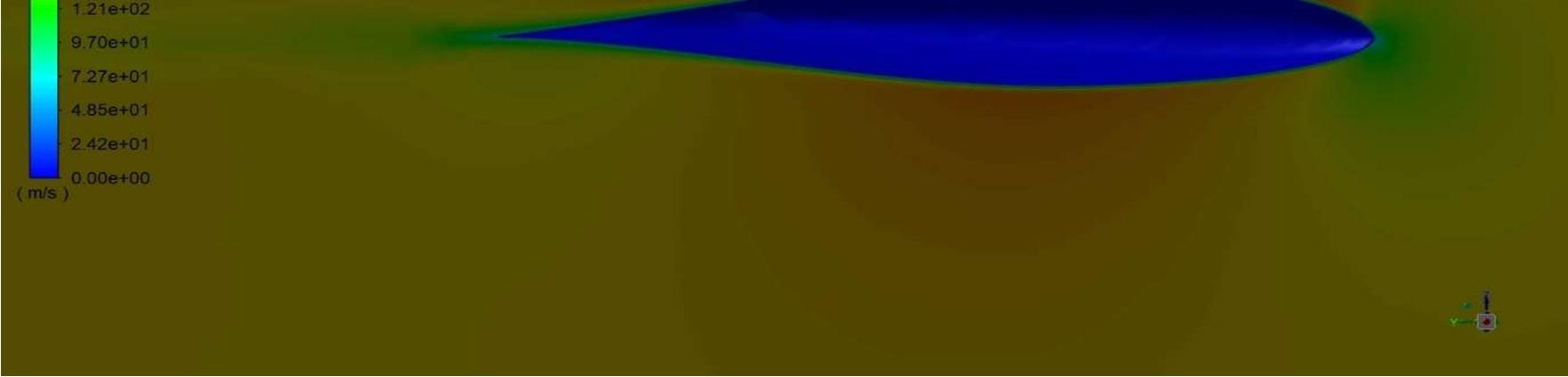
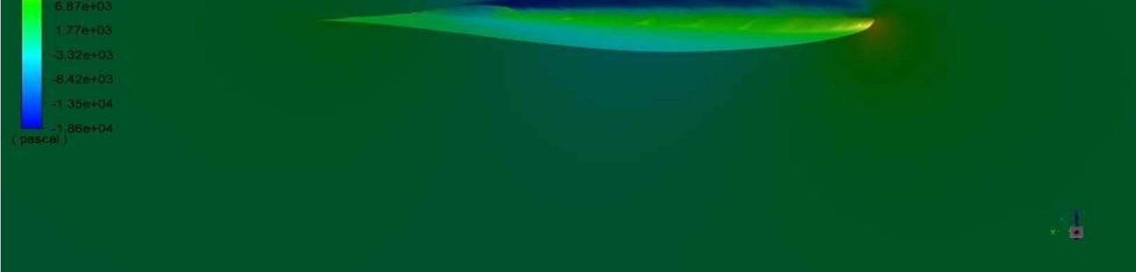
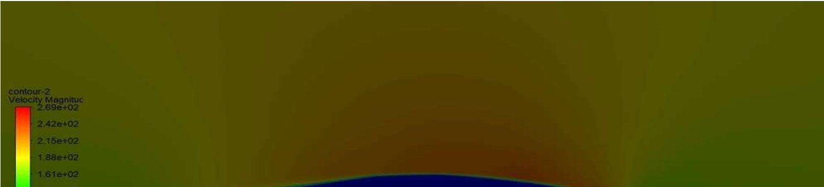
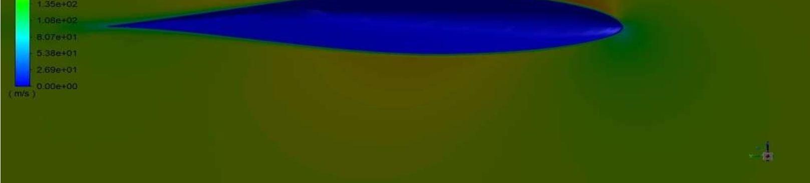
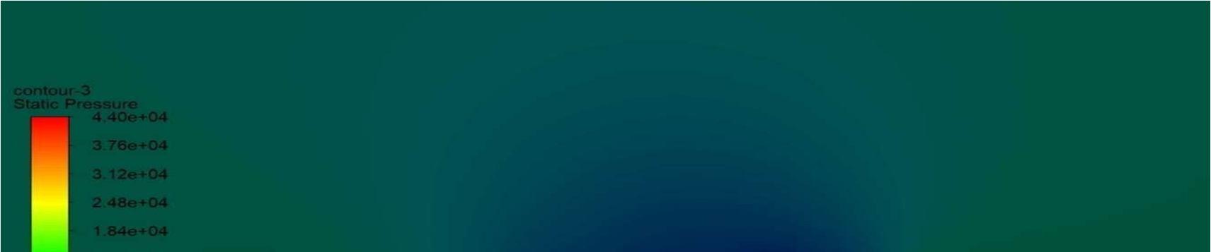
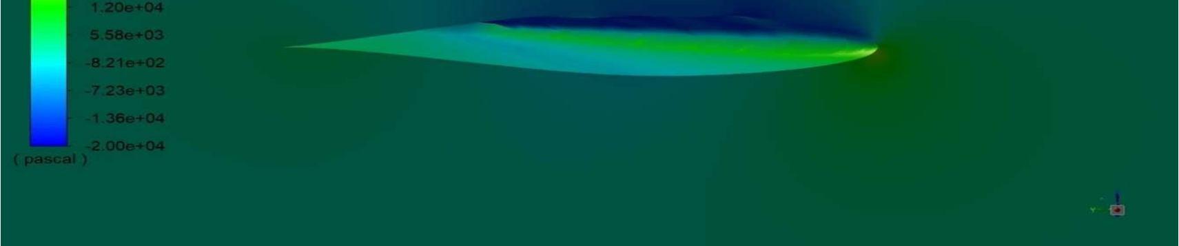
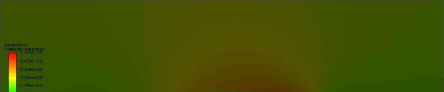
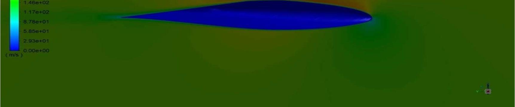
For the analysis, the model selected is the viscous spalart allmaras turbulence model. The model was developed for the analysis of aerodynamic flow. This model blends from viscous sublayer to logarithmic formula based on y+. It is 1 equation eddy viscosity transport model.
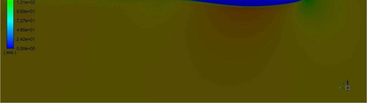
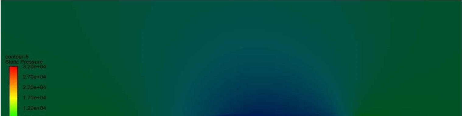
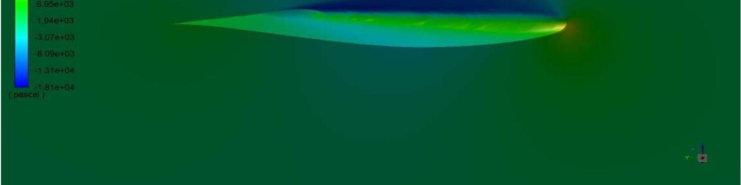
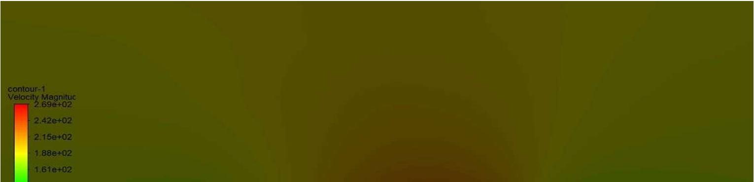
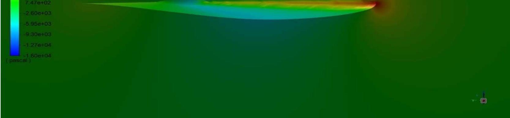
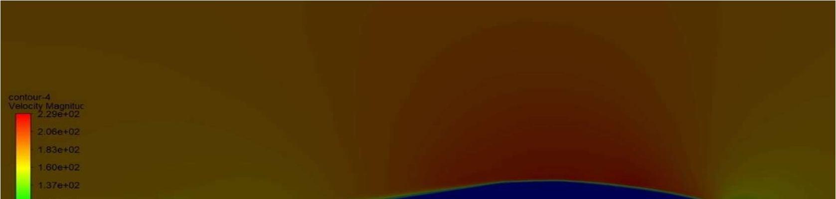
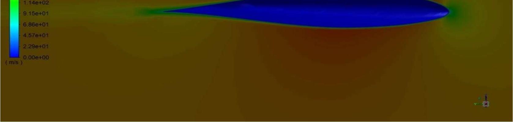
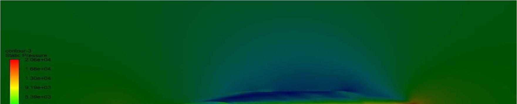
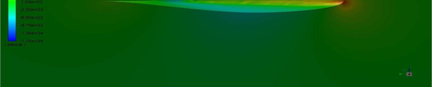
The flow velocity is taken 180m/s at 0˚to 20˚ angle of attack. The report of drag coefficientand lift coefficient is generated for both angles.

ISSN: 2321 9653; IC Value: 45.98; SJ Impact Factor: 7.538 Volume 10 Issue X Oct 2022 Available at www.ijraset.com
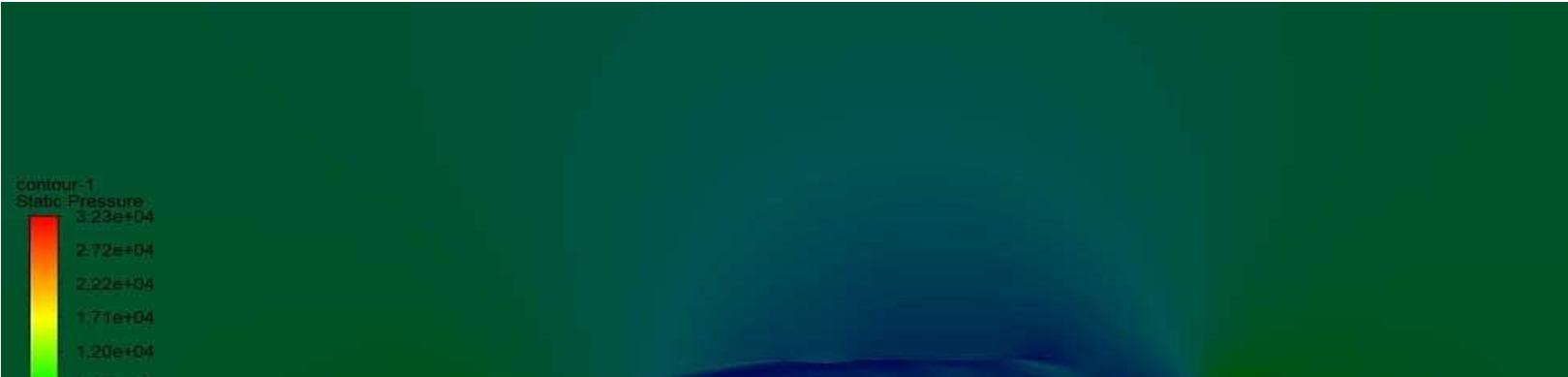
The lift coefficient and the drag coefficient of the modified airfoil is are compared with the unmodified airfoil and the percentage change in the result is tabulated for each angle of attackanalysed.
Table 4: Percentage change in results. Angle of attack % Change in drag coefficient % Change in lift coefficient 0˚ 3.814634854 1.294683776 5˚ 5.088165386 0.899239105 10˚ 8.738109268 0.550741383 15˚ 29.4027526 0.668451071 20˚ 0.022946306 2.399821014
The final result of the modified airfoil has a less drag coefficient than our modified airfoil but not much change in the lift coefficient. For years the try error method helped many researchers to make the aviation industry improve the flight more fuel efficient. The airfoil can be further modified to get a better result.
[1] Antony Jameson and James Rethuer, (1988) “Control Theory based airfoil design usingEuler's equations". DOI: https://doi.org/10.1007/BF01061285
[2] T Gultop, (1995) “An Investigation of the effect of aspect ratio on Airfoilperformance.” American Journal of Applied Sciences ISSN/EISSN: 15469239 15543641, Volume: 2, Issue: 2, Pages: 545 549.
[3] Kondapalli Siva Prasad, (2013) "Aerofoil Profile Analysis and Design Optimisation". Volume 3, Issue 2, ISSN: 2231 038X. DOI: https://doi.org/10.37591/.v3i2.656
[4] J. Fazil and V. Jayakumar, (2011) “INVESTIGATION OF AIRFOIL PROFILE DESIGN USING REVERSE ENGINEERING BEZIER CURVE”, Journal: Journal of Engineering and Applied Sciences ISSN 1819 6608 Volume: 6; Issue: 7
[5] Mr. Mayurkymar kevadiya (2013), “CFD Analysis of Pressure Coefficient for NACA 4412”, IJETT Journal, Volume 4 Issue 5
[6] Sanjay Goel, (2008),” Turbine Airfoil Optimization Using Quasi 3D Analysis Codes”, https://doi.org/10.1155/2009/531358
[7] D.A. Master and N. J. Taylor (2016)"A Geometric Comparison of Aerofoil Shape Parameterisation Methods”. https://doi.org/10.2514/6.2016 0558
[8] Khan M A, Padhy C (2021). AERODYNAMIC CHARACTERIZATION OF BIO MIMICKED PLEATED DRAGONFLY AEROFOIL, International journal of Aviation, Aeronautics and Aerospace, Volume 8, Issue 2, April/2021. DOI: https://doi.org/10.15406/fmrij.2019.03.00053
[9] Karrothu V R Manikanta, N. Muralikrishna. INVESTIGATION OF AEROFOIL FOR FLAPPING WING AIRCRAFT. http://dx.doi.org/10.17577/IJERTV4IS080094
[10] Alessandro De Gaspari, Frederic Moens “AERODYNAMIC SHAPE DESIGN AND VALIDATION OF AN ADVANCED HIGH LIFT DEVICE FOR A REGIONAL AIRCRAFT WITH MORPHING DROOP NOSE” Volume 2019, Issue 27 March 2019, Article ID 7982168.DOI: https://doi.org/10.1155/2019/7982168
[11] M N A M Asri, N A Z Abdullah, M S M Fouzi, M S M Sani “. NORMAL MODE FINITE ELEMENT ANALYSIS OF AEROFOIL WING STRUCTURE WITHDIFFERENT MATERIALS”. Journal of Physics, Conf. Series 1262, Issue:2019, ISSN: 012020,
[12] G. Praveen Dr.P. Sreenivasulu, (2018).DESIGN AND ANALYSIS OF AEROFOIL STRUCTURES TO ENHANCE AERODYNAMIC PERFORMANCE THROUGH CFD, International Journal of Research Volume 7, Issue VIII, August/2018, ISSNNO:2236 6124.
[13] MD. Safayet Hossain, Muhammad Ferdous Raiyan, Mohammed Nasir Uddin Akanda, Nahed Hassan Jony, (2014), A COMPARATIVE FLOW ANALYSIS OF NACA 6409 AND NACA 4412 AEROFOIL, International Journal of Research in Engineering and Technology eISSN: 2319 1163.
[14] Amit Kumar Thakur, Ajay Kumar Kaviti, Jayashri N Nair, (2020), The Effects of Aerofoil Profile Modification on A Vertical Axis Wind Turbine. ISSN 2277 8616
[15] Prof. E.G. Tulapurkara, Chapter 5, Lectures [19 22] Wing design. ISSN 2307 4531
[16] V. Madhanraj, E. Harish Reddy, S.Subhani Basha, "Investigation and Analysis of The Performance Characteristics of Horizontal Axis Wind Turbine Blade with Dimple By Using CFD", Vol.12 No.7 (2021), 47 52
[17] Dr. J. M. Meyers | Dr. D. G. Fletcher | Dr. Y. Dubief, "Lift and Drag on an Airfoi:ME 123: Mechanical Engineering Laboratory II: Fluids".
[18] Wenbin Song, Andrew J. Keane, "A STUDY OF SHAPE PARAMETERIZATION METHODS FOR AIRFOIL OPTIMIZATION". American institute of Aeronautics and Astronautics. Article no AIAA 2004 4482. DOI: http://:doi.org/10.2514/6.2004 4482.
[19] Y.D. Dwivedi, Tushar MS Waykar, LVSS Lohitasya Varun, "AERODYNAMIC CHARACTERIZATION OF ALBATROSS INSPIRED AIRFOILS / WINGS”. International Journal of advanced science and Technology. Volume 290, No 125,(2020), pp.801 815.
ISSN: 2321 9653; IC Value: 45.98; SJ Impact Factor: 7.538 Volume 10 Issue X Oct 2022 Available at www.ijraset.com
[20] Shubham Jain, Nekkanti Sitaram, Sriram Krishnaswamy, EFFECT OF REYNOLDS NUMBER ON AERODYNAMIC OF AIRFOIL WITH GURNEY FLAP. International Journals of rotating Machinery, Article no. 628632, 26 August 2015, DOI: http://dx.doi.org/10.1155/2015/628632.
[21] Samuel Mitchell, Iheanyichukwu Ogbonna and Konstantin Volkov. Improvement of Self Starting Capabilities of Vertical Axis Wind Turbines with New Design of Turbine Blades. Sustainability 2021, 13, 3854. https://doi.org/10.3390/su13073854.
[22] Basim A. R. Al Bakri, Radwan M. Aljuhashy (2021). The Aerodynamics of the Wavy Blade Under the Effect of Fluctuated Wind Flow. FME Transactions; 2021, Vol. 49 Issue 3, p704 710, 7p
[23] A Siddharth Reddy, Atheeq Ur Rehman, Sathvik Shetty, Shashank Vivek, Gajanan, Efficient Aerodynamic System of Rear and Front Wings for an FSAE Car.ISSN: 2582 8819
[24] D.S. Lee, L. F. Gonzalez, J. Periaux, E. Onate. ROBUST (2012) AERODYNAMIC DESIGN OPTIMISATION OF MORPHING AEROFOIL/WING USING DISTRIBUTED MOGA. DOI: https://doi.org/10.1109/CEC.2012.6256429