
ISSN: 2321 9653; IC Value: 45.98; SJ Impact Factor: 7.538

Volume 10 Issue XI Nov 2022 Available at www.ijraset.com


ISSN: 2321 9653; IC Value: 45.98; SJ Impact Factor: 7.538

Volume 10 Issue XI Nov 2022 Available at www.ijraset.com

Ambuj Gupta1 , Yajur Shridhar2 ,Gayathri Mohan3 ,Shubham Tyagi4 1, 2, 3
UG Civil, Amity School of Engineering and Technology, Amity University, Sec 125 Noida, U.P. (201301) 4Department of Civil Amity School of Engineering and Technology, Amity University, Sec 125 Noida, U.P. (201301)
Abstract: It has been observed that millions of dollars are being invested on highway/subway tunnel maintenanceand restoration all over the globe. But this cost can be minimized if the detection of cracks will be found as earlieras possible. As the restoration process depends on the type of cracks, it is important to plan the required steps to be taken for repairing the destruction caused as earlier as possible. Initially we need to capture very transparent images of the roads/concrete infrastructures as the detection process will depend on those images. The device usedfor scanning and capturing the images of the concrete infrastructures or roads must be configured for picturing high resolution images. After processing the image acquired, it is easier to extract information about the cracks found. Depending on this information, the images could be classified using some decision making algorithm. Thisprocedure can be implemented on images acquired by any objects or vehicles carrying image sensing terminal, laser distance sensor, image storage and processing servers, central control system and speed sensor. The accuracydepends on the image’s quality and accurate capture.
Keywords: Crack detection, Image processing, Machine learning, Infrastructural health monitoring.
While travelling, road safety is an important factor. If the road conditions are safe and sound, then the chances ofaccidents will automatically decrease. In modern countries, they have long highways and it’s very difficult to inspect these roads by manpower, hence an efficient automatic detection of the road condition can be developed for making them safe. These cracks of the highways can be classified into some types. Depending on those cracks,authority must take actions how those would have to repair. Initially it may need to detect the location of the cracks. To perform that, a visual inspection technique is needed to capture images of the roads and then to be analyzed. Therefore, our ultimate goal is to develop a system that can be able to detect these cracks on the highways automatically. Hence our ultimate goal is to develop a system that can be able to detect these cracks on the highways automatically. Tools to detect any weakness in the component. however, this strategy is dreary, labor and inclinedto human mistake. Programmed break location manages utilizing innovations to distinguish breaks from foundations. The degree of corruption can be dictated by examining the length, width, profundityand seriousnessof a break. These actions can be utilized to settle on choices in regards to the arrangement of the break, strength of the construction and its use Utilizing the customary examination systems which include manualinvestigation,it is exceptionally tedious to decide the break estimates which make it hard to make derivation in regards to the degree of debasement. Thus, for a speedy, viable, and solid harm evaluation, the break identification process should be mechanized to supplant the manual imperfection assessment strategies. Some testing strategies like laser, infrared, warm,radiographic, and warm testing approaches have been utilized in the past to computerize thecourse of break recognition. However, more recently, there has been an increasing tendency of using image basedmethods for identifying cracks. These techniques include catching pictures of the objective part and breaking down them automatically to find and arrange breaks. Such techniques are quick, more affordable, and strong. Thetechniques can be ordered into two sorts specifically as picture handling and AI. The picture handling strategies don't need a model preparing process and include the utilization of channels, morphological investigation, measurable strategies, and permeation procedures for the recognition of break On the other hand, the AI interaction includes the assortment of a dataset of pictures, which are provided to the chose AI model for preparing Such techniques might include picture handling ventures for pre handling and clamor expulsion, yet the break recognition task is finished by the prepared AI model. the fundamental design of a picture handling based technique for break location. First utilizing a camera or some other imaging system, high goal pictures of the objective part are gathered. The pictures are then pre handled which includes utilizing channels, division and different ways to deal with eliminatecommotion and shadowfrom the picture. Thepicture might bechanged overto grayscale or double structure whenever needed by the particular break identification strategy being utilized.
ISSN: 2321 9653; IC Value: 45.98; SJ Impact Factor: 7.538 Volume 10 Issue XI Nov 2022 Available at www.ijraset.com

The resultant picture is applied to the break recognition strategy which uses picture handling strategies like edgelocation, division, or pixel examination to feature or section the broke part in the picture. Parameter estimation involve calculating the specific properties of the identified crack such as its length, width, depth and density. Suchmeasure help to make decision regarding the difficulty of a cracks.
Crack detection methodology can be classified as following: 1) Image capture 2) Image processing 3) Image Segmentation 4) Feature extraction
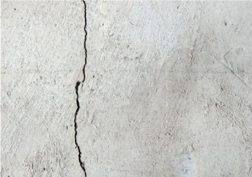
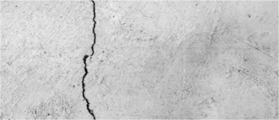
Any device can be installed on a vehicle zenith point or in a pole that is capable of capturing high resolute imagesof highways, but focus should be perfect, and the image should be accurate and precise. If needed, the original images could be resized. Here are some examples of images on which we are going to detect cracks.
Figure 1. Sample image of crack.



Steps in the processing section are elaborated below.
1) Gray Scaling And Averaging
Firstly, the images is transformed in a new one in grayscale and blur. These make the images easier to visualize the processed images in next steps. Below shown are the blurred images. Algorithm is used for gray scaling and averaging. # Convert into gray scale gray = cv2.cvtColor(img, cv2.COLOR_BGR2GRAY)# Image processing ( smoothing ) # Averaging blur = cv2.blur(gray,(3,3))
Figure 2. Blurred Image
ISSN: 2321 9653; IC Value: 45.98; SJ Impact Factor: 7.538 Volume 10 Issue XI Nov 2022 Available at www.ijraset.com

Logarithmic transformation is used to replace all the pixels values of an image with the respective logarithmic values. This transformation is used for image enhancement since the dark pixels gets expanded of the image as compared to greater pixel values. When this method is applied, images having greater pixel value will get enhanced more and the original data or information will be misplaced. Now after applying the log transformation in to our sample blurred images, they will come out looking like the below images.
# Apply logarithmic transform _log = (img np.log(blur+1)/(np.log(1+np.max(blur))))*255
# Specify the data type img_log =np.array(img_log,dtype=np.uint8)
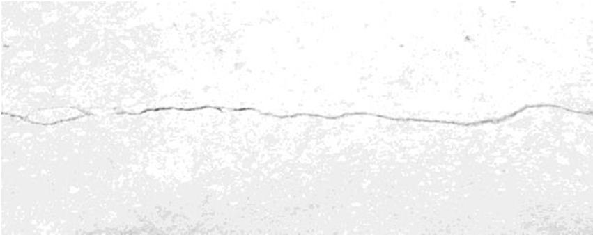
Figure 3. Log transformed image.
Similar to other filters, the bilateral filter is also based on a space domain Gaussian filter, though unlike others itadditionally uses another (multiplicative) Gaussian filter component that helps with pixel intensity differences. The technique saves edges which help exhibit a high variation in intensity in comparison to the centre pixel and would not be added for the purpose of blurring. Hence the sampled logarithmic transformed images transform toas presented below after applying bilateral filter.
# Image smoothing: bilateral filter bilateral = cv2.bilateralFilter(img_log, 5, 75, 75)

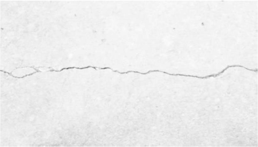


Figure 4: Bilateral Filtered Image.
Canny edge detection is used on different vision objects as a technique to extract all the useful structural component information. This helps reduce the quantity of data to be processed dramatically. A multi stage algorithm is used to detect a huge range of edge from image. Three main steps that the Canny algorithm consistsof are as follows: Calculate the scale of the gradient vector for each pixel and therefore find the intensity gradient of theimage “Thin” out the edges to attain and edge with width of one pixel i.e. non maximum suppression Lastly to reduce fake edges a double step threshold hysteresis is applied i.e. Threshold hysteresis

ISSN: 2321 9653; IC Value: 45.98; SJ Impact Factor: 7.538 Volume 10 Issue XI Nov 2022 Available at www.ijraset.com



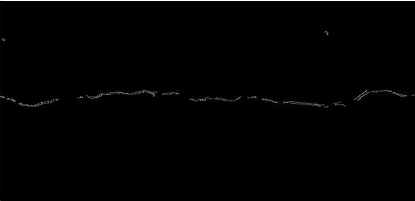
Now to detect the edges of cracks in our bilaterally filtered image we apply canny algorithm.
import numpy as np import cv2 as cv from matplotlib import pyplot as plt img = cv.imread(r'C:\Users\Asus\Downloads\crack.jpg',0) edges = cv.Canny(img,100,200) plt.subplot(121),plt.imshow(img,cmap = 'gray') plt.title('Original Image'), plt.xticks([]), plt.yticks([]) plt.subplot(122),plt.imshow(edges,cmap = 'gray') plt.title('Edge Image'), plt.xticks([]), plt.yticks([]) plt.show()

Figure 5 .Canny edge image.
Morphological transformations are primary transformations that are done based on the shape of the image. Morphological operation is mostly performed on a There exist a lot of different morphological filtering ,though after understanding the results, the most suitable filter for detection in this case is the closing filter .Closing filter is helpful in filling small gaps in the picture that make the main crack continuous and highly detailed . It also helps in closing minor holes inside the objects in foreground or minor black points on the object. Closing filter has been defined as a dilation leading to an erosion. We apply morphological closing operation on the canny edges detected images here. # Morphological Closing Operatorkernel = np.ones((5,5),np.uint8) closing = cv2.morphologyEx(edges, cv2.MORPH_CLOSE, kernel)
Figure 6 . Morphological Closing Image.
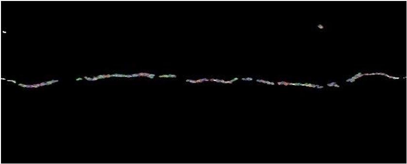
Various types of algorithm can be found that can be useful in feature detection and extraction some algorithms like SURF and SIFT are patented and are not free for public ,while others like ORB are free and useable ,ThoughORB is faster ,SIFT and SURF are able to detect more feature .ORB is an acronym for oriented fast and rotated brief. It adds qualities of BRIFE and FAST for feature description and extraction. It has efficient memory use and a veryhigh matching accuracy. Instead of SURF and SIFT , ORB can be used for feature extraction. So after applying this ORB method into our morphological closing images we get the result as following.
ISSN: 2321 9653; IC Value: 45.98; SJ Impact Factor: 7.538
Volume 10 Issue XI Nov 2022 Available at www.ijraset.com
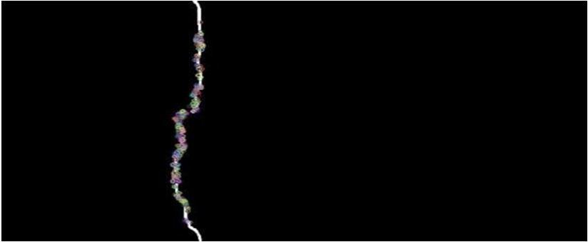
After theapplication of ORB method on the morphological closing images we obtain the following result.# Create feature detecting method
# sift = cv2.xfeatures2d.SIFT_create()
# surf = cv2.xfeatures2d.SURF_create()orb = cv2.ORB_create(nfeatures=1500)
# Make featured Image keypoints, descriptors = orb.detectAndCompute(closing, None)featuredImg = cv2.drawKeypoints(closing, keypoints, None)
a) Create An Output Images

Algorithm is used for create an output images. cv2.imwrite(r'C:\Users\Asus\Downloads\Major project\Cracked_05.jpg', featuredImg)
b) Use The Plot To Show Original And Output Images
plt.subplot(121),plt.imshow(img) plt.title('Original'),plt.xticks([]), plt.yticks([]) plt.subplot(122),plt.imshow(featuredImg,cmap='gray')plt.title('Output Image'),plt.xticks([]), plt.yticks([])
Attempt was made and a sample size of twenty images was used of both non crack and to test the program. All ofthe times, the cracks become highly detectable and visible precisely in the output images. Hence we can claim that 90% accuracy is possible if pictures aretransparent or veryclear. Based on thefinal output images, theimagescan be classified into various crack types and some classification techniques need to be applied for that.
An image processing technique for quick and auto mated break discovery for squeezed board items was proposedin this article. The objective item was removed from foundations by considering the shading factor. The edge lineof the item was then separated utilizing the permeation interaction. Since the permeation cycle is computationally escalated, the speed increase process was likewise acquainted with diminish the handling time. At last, breaks were identified and confined with the interesting edge line examination created in this review. For approval of the proposed strategy, a few experiment examinations were performed. Through tests, it was shown that the proposed picture handling strategy had the option to identify surface breaks with sensible exactness and speed. The proposed picture handling strategy could be productively utilized for break identification in the squeezed board with the upsides of cost decrease, quick investigation, and high exactness. Our future endeavours incorporate diminishing the handling time, streamlining the picture goal for break location, improving the affectability to hairline or imperceptible breaks, and coordinating equipment and programming for field arrangement.
[1] Du H and Klamecki BE. Force sensors embedded in surfaces for manufacturing and other tribologicalprocess monitoring. J Manuf Sci Eng: T ASME 1999; 121(4): 739 748.

[2] Mahayotsanun N, Cao J, Peshkin M, et al. Integrated sensing system for stamping monitoring control. In: Proceedings of the IEEE SENSORS 2007 conference, Atlanta, GA, 23 31 October 2007, pp. 1376 1379. New York: IEEE.
[3] Mohan A and Poobal S. Crack detection using image processing: a critical review and analysis. Alex Eng J. Epub ahead of print 15 February 2017. DOI: 10.1016/ j.aej.2017.01.020.
[4] Otsu N. A threshold selection method from gray level histograms. IEEE Syst Man Cyb 1979; 9(1): 62 66
[5] Ng H. Automatic thresholding for defect detection. Pattern Recogn Lett 2006; 27(14): 1644 1649.
ISSN: 2321 9653; IC Value: 45.98; SJ Impact Factor: 7.538 Volume 10 Issue XI Nov 2022 Available at www.ijraset.com
[6] Mahgoub A, Talab A, Huang Z, et al. Detection crack in image using Otsu method and multiple filteringin image processing techniques. Int J Light Electr Opt 2016; 127(3): 1030 1033.

[7] Yamaguchi T and Hashimoto S. Fast crack detection method for large size concrete surface images usingpercolation based image processing. Mach Vis Appl 2010; 21(5): 797 809.
[8] Qu Z, Lin L, Guo Y, et al. An improved algorithm for image crack detection based on percolation model. IEEJ T Electr Electr Eng 2015; 10(2): 214 221.
[9] Sinha SK and Fieguth PW. Morphological segmentation and classification of underground pipe images. JMach Vis Appl 2006; 17(1): 21 31.
[10] Landstrom A and Thurley MJ. Morphology based crack detection for steel slabs. IEEE J Sel Top Signa2012; 6(7): 866 875.
[11] Shivaprasad K, Vishwanath MK, Narasimha K, et al. Morphologybased surface crack detection. J Adv ResSci 2015; 1(1): 15 20.

[12] Reda Taha MM, Noureldin A, Lucero JL, et al. Wavelet transform for structural health monitoring: acompendium of uses and features. Struct Health Monit 2006; 5(3): 267 295.
[13] Zhu XQ and Law SS. Wavelet based crack identification of bridge beam from operational deflection timehistory. Int J Solid Struct 2006; 43(7 8): 2299 2317.
