10 XI November 2022 https://doi.org/10.22214/ijraset.2022.47667
ISSN: 2321 9653; IC Value: 45.98; SJ Impact Factor: 7.538 Volume 10 Issue XI Nov 2022 Available at www.ijraset.com


ISSN: 2321 9653; IC Value: 45.98; SJ Impact Factor: 7.538 Volume 10 Issue XI Nov 2022 Available at www.ijraset.com
1
1, 2,

2
3
Abstract: The environmental impact of ICE automobiles in the late twentieth and early twenty-first centuries prompted the development of electric vehicles. Electric vehicles have numerous advantages over traditional internal combustion engines (ICE) vehicles, including the fact that they emit no carbon dioxide into the atmosphere. With many advantages of electric vehicles over traditional ICE vehicles, the world is moving toward EVs as a new improved means of transportation. Electric vehicles' tank to wheel efficiency is three times larger than ICE vehicles', and electric vehicles have very low running and maintenance costs. Even though electric vehicles are the best alternative, they do have significant disadvantages that are listed in the problem statement. Our proposal aims to bridge the gap between pure electric and traditional ICE automobiles by combining the primary benefits and advantages of both technologies. The project's main goal is to convert any existing ICE car into the most efficient vehicle possible. Our car can basically run on two distinct independent sources of energy, or even a combination of both. It can function as a pure electric vehicle, a pure ICE vehicle, or a hybrid AWD vehicle (where high amount of power is required). It has been shown that the average city dweller does not drive his or her car for more than 25 kilometers per day, and that the vehicle is parked the majority of the time. As a result, that individual can traverse that distance in pure electric mode, and our vehicle's solar charging mechanism will recover/recharge the energy expended while on the road. As a result, the person will be able to use our vehicle for free to generate sustainable energy. The use of ICE vehicles is rapidly increasing pollution in the environment; even pure EVs are an indirect source of pollution because the bulk of power is still generated by burning coal, thus our vehicle's use will undoubtedly make a significant difference.
Keywords: Electric vehicle, hybrid EV, IC engine to EV conversion kit, Li-ion Battery System for HEV.
In late 20th and 21st century the environmental impact due to ICE vehicles led to the development of vehicle which were powered by electricity. Electric vehicles have so many advantages over conventional ICE vehicles such as electric vehicles have zero carbon emission in the atmosphere. The tank to wheel efficiency of electrical vehicles is three times greater than ICE vehicles, electric vehicles have very low running as well as maintenance cost, with many advantages of electric vehicles towards conventional ICE vehicles the world is moving toward EVs as new improvised mode of transportation. Even being the optimum option still electric vehicles hold some drawbacks which are mentioned in problem statement. Our project entirely focusses on covering up the gap between pure electric and conventional ICE vehicles by merging the major advantages and privilege of both the technologies. Major focus of project is to take any existing ICE vehicle and transfigure it into most optimum vehicle. Basically, our vehicle can run on two different independent sources of energies and even combined utilization of both mediums, the vehicle can be run as pure electric vehicle, pure ICE vehicle and hybrid AWD vehicle (where high amount of power is required). It has been observed that an average person in the city doesn’t drive his/her vehicle for more than 25 km everyday also most of the time vehicle is parked. Hence that particular person can feasibly cover that amount of distance with pure electric mode and our vehicles solar charging feature will recover/recharge the amount of energy exhausted on the run. Hence our vehicle will provide free clean energy usage to the person. Usage of ICE vehicles is leading to the rapid proliferation of pollution in the atmosphere, even pure EVs are indirect source of pollution as majority of electricity is still produced by burning coal hence usage of our vehicle will definitely make a huge change.
When a person has to travel long distance then that person cannot rely on the electric energy/mode of the car because of low range issue of EVs and lack of charging stations and even if charging station is found then that person has to wait for hours to get car charged. Hence to overcome this particular problem the person can use the pure ICE mode to travel as much distance as he wants to cover with petrol/diesel.
ISSN: 2321 9653; IC Value: 45.98; SJ Impact Factor: 7.538
Volume 10 Issue XI Nov 2022 Available at www.ijraset.com
When a person has to travel less distance like around >100 km then that person can use the pure electric mode in which the car will be driven by the electric motors present at rear wheels and as already discussed this will be most efficient way as it is powered by solar energy.
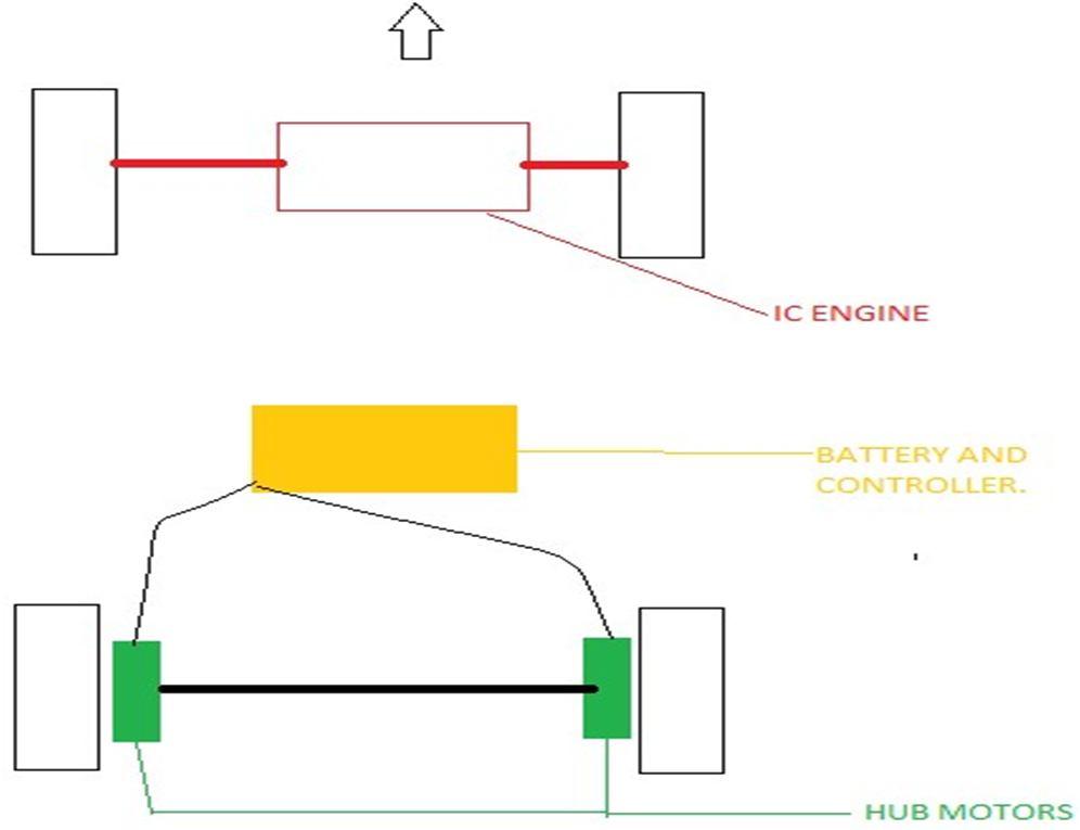
When the driver demands high performance, power and speed which cannot be achieved by the electric motors then the engine which is already present in the car will provide assist to the drive and then the power will be generated mutually, then the person can drive the car on highways as well as in off road zones as car will have AWD without caring about the limited power of motors. The main feature of hybrid AWD mode is cylinder cut off technology which will save a decent amount of fuel. What will happen during that is the driver does not want the excessive power and the cylinder will get cut off and the fuel will get saved.
P. Di Giorgio et.al [1] presented the design, development and testing of a novel hybrid power unit based on a passive fuel cell/battery system. The proposed power unit configuration does not need costly power converters, and has higher overall performances with respect to active DC/ DC controlled configurations; as a matter of fact, this solution is simple and cheap and its application is interesting on lightweight vehicles. The coupling of the fuel cell unit and of the battery pack is performed by using two high power resistors, that avoid current spikes and possible damages of the components. The developed power unit consists of: • Five fuel cell stacks (Horizon 500 W LT PEM) series connected • 72 V battery pack (LiFePO4) • Two resistors (9 Ω each) When connected, the fuel cell unit and the battery pack operate at the same voltage, neglecting the voltage loss of the diode and on the switch, and the powers produced by the fuel cell stack and the battery pack only depend on the components behaviour under load condition. The analysis on the power unit behaviour and performance has been carried out by means of a numerical model and experimental activities. The power unit has been tested taking into account the power profile derived from the Artemis urban cycle for a three wheel vehicle. The average power demand for one cycle resulted to be 1.57 kW considering the regenerative breaking. Since the electronic loads do not support regenerative breaking testing, the average power of the actual duty cycle is 1.97 kW. The connection between the fuel cell unit and the battery pack has been realized through the dummy resistances in order to avoid malfunction of the two components.
Yoshikazu Nishida et.al [2] developed adaptive battery state detection technology for LIB systems mounted in HEV. Based on calculated information, battery control technology of the following kind was created. In order to prevent overcharge, a system was constructed that can reliably detect overcharge. This system has a cell voltage sensor in each cell and also detects voltage sensor failure. The system continuously performs estimation of the battery state in terms of the SOC and capacity of each cell. Providing optimal control of the SOC range has enabled achievement of a technology that balances assurance of the energy needed by the vehicle with driving force and durability. Each cell is equipped with a discharge circuit and the use of a levelling method based on calculation of individual cell capacity which has enabled effective use of battery energy in the SOC control range.
ISSN: 2321 9653; IC Value: 45.98; SJ Impact Factor: 7.538
Volume 10 Issue XI Nov 2022 Available at www.ijraset.com
Thomas Nemeth et.al [3] in his paper proposes a deep Q learning based energy management strategy for hybrid battery systems in electric vehicles.
As far as we know, this is the first work that investigates the learning based energy management strategies for electric vehicles with hybrid battery systems. In contrast to the rigid constraints for the battery pack’s SoC in the pioneering works, we provide a novel reward term to make the agent search for the optimal SoC range itself. Combined with other terms concerning the energy loss and physical constraints of the batteries, the intended reward function guarantees the optimal operation of the high energy and high power pack with the minimization of the energy loss and the improvement of both electrical and thermal safety. For the first time, randomly selected driving cycles are implemented in each training epoch, ensuring the strategy’s adaptiveness to various scenarios and uncertainties. The training and validation results illustrate that the proposed deep Q learning based energy management strategy achieves the safe and efficient operation of each battery pack. Compared with the Q learning based strategy, the proposed method achieved a lower energy loss of the system while reduced the training time by 96.5% and the computation time by 55.4%. Furthermore, future work with the learning based energy management for hybrid battery systems and subsequent exploration areas is discussed.
Joao L. Afonso et.al [4] stated regarding EV battery chargers (EVBC), both wired and wireless power transfer technologies. A review of power electronics converters that can be used for on board and off board EVBC is presented, covering the main topologies that can be used in the front end and back end power stages. Some developed laboratory prototypes are also presented, including on board and off board EVBC, along with illustrative experimental results obtained for the main operation modes. As demonstrated, both on board and off board EVBC are fundamental in supporting the integration of EVs into the power grid, presenting innovative features far beyond the simple charging process, e.g., bidirectional systems allow the exchange of active power with the grid, and also other features, such as the operation in isolated mode or the possibility of contributing to improving the electrical power grid quality. In this context, for selecting the more interesting power electronics topologies for on board or off board EVBC, the key features that should be considered are: the multilevel and interleaved characteristic for reducing the coupling passive filters; The four quadrant operation to ensure that the bidirectional power flow is possible (allowing operation in G2V, V2G, V2H, and other modes). Still regarding EVBC, some solutions based on dc dc converters to provide power to the auxiliary battery from the EV battery are also presented.
Huanwei Xu et.al [5] stated that the optimization design goal is to minimize the MTD of the automobile lithium battery pack. From the aspects of structural rationality, fluid mechanics and heat transfer, the cooling and heat dissipation system with two kinds of liquid cooling channel structures are analysed: serpentine and U shaped. By comparing the thermal analysis simulation results of the two cooling structures, the serpentine cooling channel with better cooling effect is selected as the structure to be optimized. In order to minimize the MTD of the serpentine cooling channel of lithium battery pack, an optimization framework based on adaptive ensemble of surrogate models is proposed. Compared with the initial solution, the MTD and the maximum temperature of lithium battery pack obtained by the proposed framework are 3.46 K and 301.63 K, respectively, which are reduced by 7.49% and 0.04%. The optimization results show that the proposed framework can solve implicit optimization problem with less samples and find the global optimal solution and avoid falling into local optimal solution. However, this paper only uses the adaptive ensemble of surrogate models to optimize the maximum temperature difference. Considering multi objective attributes of automobile.
Dongping XU et.al [6] , stated that due to its higher power density and technological potential, Li ion battery has gained more and more attention in HEV research and production.
The centres on measurement of cells voltage, battery temperature, battery voltage and battery current as well as calculation of the current integration. It introduces one method that uses specific IC to measure Li ion battery cells voltage, battery temperature and cells balancing, which is more simple and practical, cost saving and more precise. Besides, it gives a research of tow methods to calculate Ah value: one is by using software integration method and the other is by using Single Phase Multifunction Metering IC. After comparison of two group experimental data, the result is: by using Single Phase Multifunction Metering IC to calculate Ah value is cost saving, with less difference and better practical effect, compared with usage of software integration method.
Tiano Francesco Antonio et.al [7] ,founded a model able to estimate temperature for PV panels installed on a car under real meteorological conditions is developed. Results showed that the parking phases are the most critical, where the increase in the photovoltaic panels temperature to a sensible reduction of their efficiency. Nonetheless, the energy produced by the panels can represent the majority of the energy spent in the urban use of a vehicle.
ISSN: 2321 9653; IC Value: 45.98; SJ Impact Factor: 7.538 Volume 10 Issue XI Nov 2022 Available at www.ijraset.com
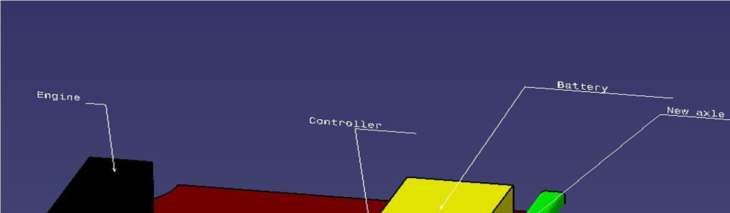
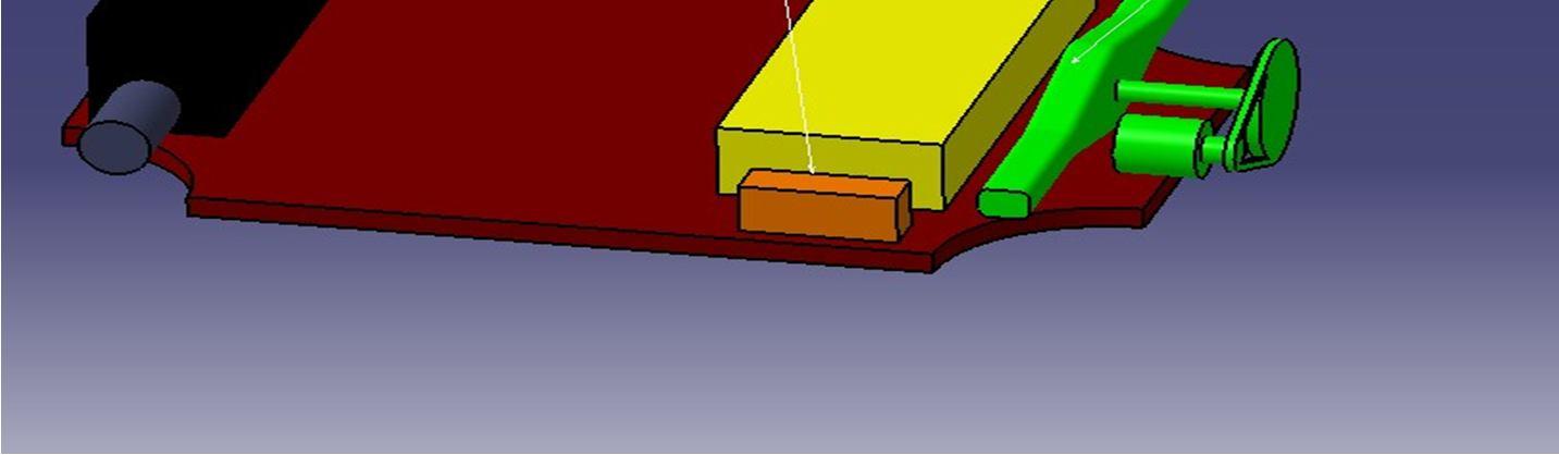
It has been observed that best place where we can put extra power without affecting the structural integrity of car are rear wheels which were independently free earlier.
The new source of power or the source which is going to generate power should be strong and optimum for the vehicle. now for getting the optimum power we have to consider different forces and resistances which are going to act on the vehicle when it is stationary as well as in motion.
The calculation below will give exact power and torque required.
Weight of vehicle = 900 kg
Length of vehicle = 3335 mm
Width of vehicle = 1440 mm
Height of vehicle = 1475 mm
Area = height x width = 1475x1440
Wheel radius = 0.3 m
Linear wheel travel = 1.9 m
Velocity = 11.11 m/s
RPM required = 350
Gravitational constant = 9.8 m/s
Coefficient of rolling resistance = 0.02
Air density = 1.23 [1]
Coefficient of drag = 0.41 [2]
Now we know,
Rolling= m x g x v x rolling R
P drag= air density x drags x a x v^3
P gradient= m x g x sin10 x v
Power = (m x g x v x rolling R) + (air density x drags x a x v^3) + (m x g x sin10 x v) = (900x9.8x11.1x0.02) + (1.23x0.41x2.1x11.1x11.1x11.1) + (900x9.8x0.17 x 1) = 4133.05 W.
As now we know power required to overcome the resistances, we can also calculate the torque required.
Torque = power X 60/ (2 X 3.14 X N)
Torque = 112 Nm.
To verify the following torque required to run the vehicle Indian driving Cycle has to be matched to the value to prove that motor selection is proper.
A driving cycle is a series of data points representing the speed of a vehicle versus time. Driving cycles are produced by different countries and organizations to assess the performance of vehicles in various ways, as for instance fuel consumption, electric vehicle autonomy and polluting emissions.
Fuel consumption and emission tests are performed on chassis dynamometers.
Tailpipe emissions are collected and measured to indicate the performance of the vehicle.
Another use for driving cycles is in vehicle simulations.
More specifically, they are used in propulsion system simulations to predict performance of internal combustion engines, transmissions, electric drive systems, batteries, fuel cell systems, and similar components.
Some driving cycles are derived theoretically, as it is preferred in the European Union, whereas others are direct measurements of a driving pattern deemed representative.
There are two types of driving cycles:
1) Transient driving cycles involve many changes, representing the constant speed changes typical of on road driving.
2) Modal driving cycles involve protracted periods at constant speeds.
3) Drive cycle recognition is applying to Hybrid Electric Vehicle.
ISSN: 2321 9653; IC Value: 45.98; SJ Impact Factor: 7.538 Volume 10 Issue XI Nov 2022 Available at www.ijraset.com
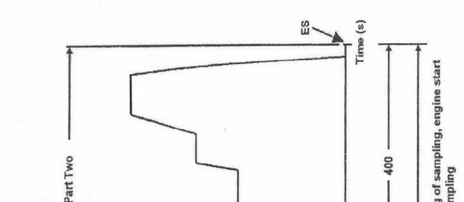
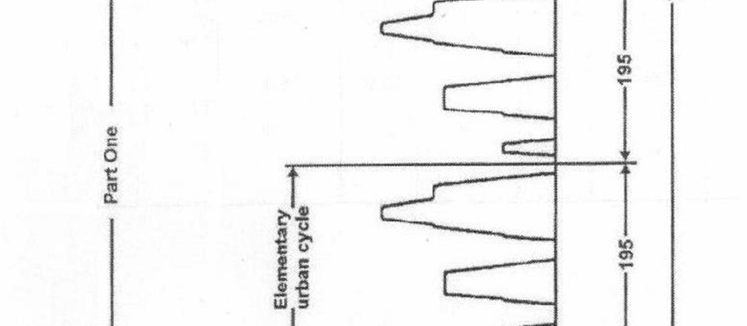
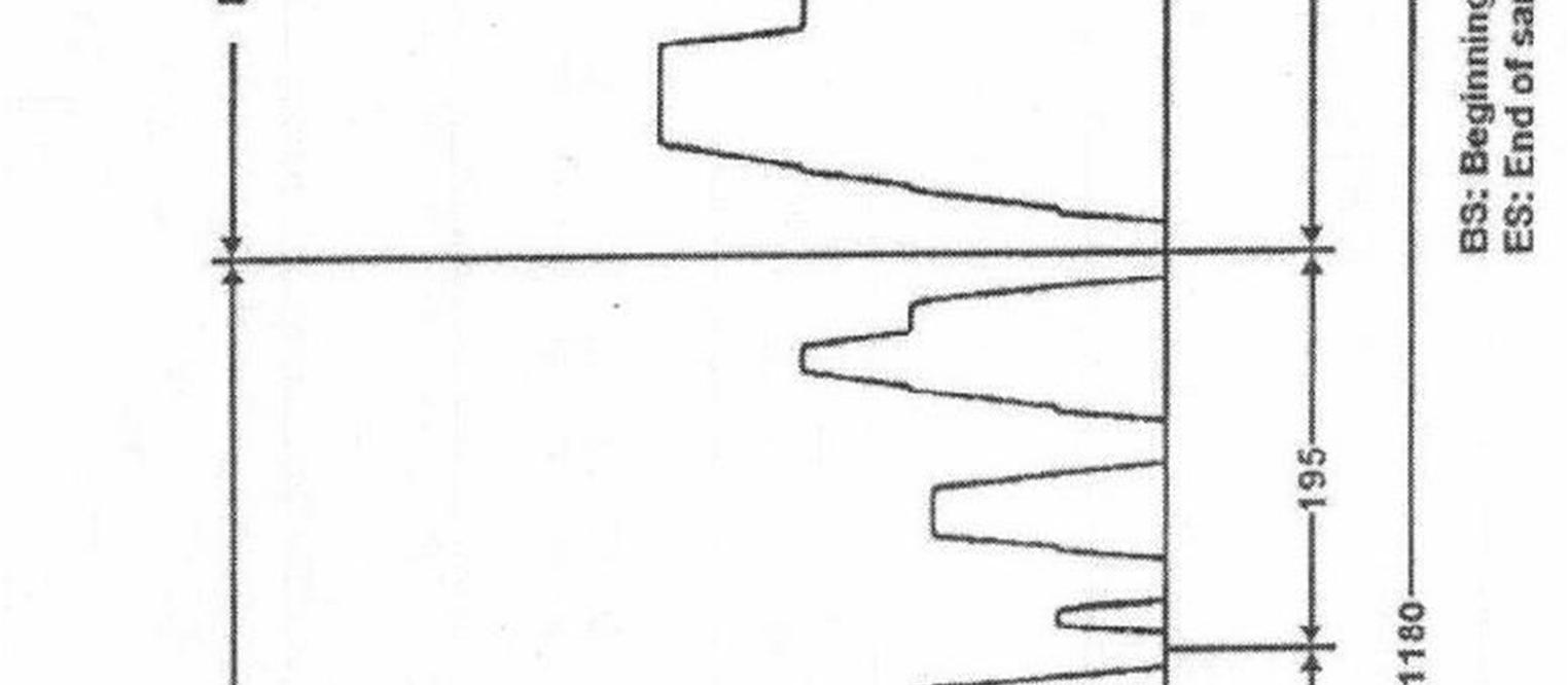
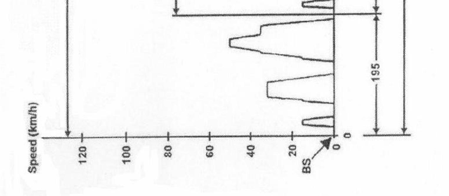
Figure 3 2 General plotting of IDC
ISSN: 2321 9653; IC Value: 45.98; SJ Impact Factor: 7.538 Volume 10 Issue XI Nov 2022 Available at www.ijraset.com


1 Idling 1 20 20 20 K1 (*) 2 Acceleration 2 0.83 0 15 5 41 25 1 1562.5 0.002170139 3 Gear change 2 27 766.38 0.000425767 4 Acceleration 0.62 15 35 9 36 2 1543 0.0038575 5 Gear change 2 38 2113.645 0.001174247 6 Acceleration 0.52 35 50 8 46 3 976.563 0.00217014 7 Gear change 2 48 3612.23 0.002006794 8 Acceleration 0.43 50 70 13 61 4 1068.376 0.003858024 9 Steady Speed 3 70 50 50 111 5 6619.159 0.091932764 10 Deceleration 4 0.69 70 50 8 8 119 4 s 5 + 4 s 4 0 11 Steady Speed 5 50 69 69 188 4 3612.23 0.069234408 12 Acceleration 6 0.43 50 70 13 13 201 4 1068.376 0.003858024 13 Steady Speed 7 70 50 50 251 5 6619.159 0.091932764 14 Acceleration 8 0.24 70 90 24 24 275 5 578.704 0.003858027 15 Steady Speed 9 90 83 83 358 5 11188.125 0.257948438 16 Deceleration 10 0.69 90 80 4 22 362 5 0 17 Deceleration 1.04 80 50 8 370 5 0 18 Deceleration 1.39 50 00 10 380 K5 (*) 0 19 Idle 11 20 20 400 PM (*) 0
ISSN: 2321 9653; IC Value: 45.98; SJ Impact Factor: 7.538 Volume 10 Issue XI Nov 2022 Available at www.ijraset.com

Power requirement were calculated according to the standard Indian Drive Cycle for city. Vehicle dimensions, weight, required accelerations and speeds were given as an input to the above mentioned table. From the table it was observed that power requirement was maximum of value 3612.23 Watts at time = 155 secs which was required to overcome rolling resistances and air drag hence the energy consumed at that point of time was 12.041Wh. Therefore, this assisted in the motor selection from the catalogue.

Given: Power = 6KW and 72V. For motor • Solution:
Step 1: Find out the current (in Amp.) consumed by a motor to run P = V X I 6000 = 72 x I I = 83.33 A (theoretically)
Step 2: Find out the watt hour of the battery To run 6000 watt motor for 1 hour = 6000 X 1 = 6000 WHR.
Taking efficiency of battery about 80% i.e., 6000/0.8 = 7500 WHR
Step 3: Convert watt hr. of battery into amp. Hr. of battery P = V X I 7500 = 72 X AH. Amp hr. = 104.167 A Hr.
It has been observed that best place where we can put extra power without affecting the structural integrity of car are rear wheels which were independently free earlier. The new source of power or the source which is going to generate power should be strong and optimum for the vehicle. now for getting the optimum power we have to consider different forces and resistances which are going to act on the vehicle when it is stationary as well as in motion. The calculation below will give exact power and torque required. Weight of vehicle = 800 kg
Length of vehicle = 3335 mm
Width of vehicle = 1440 mm
Height of vehicle = 1475 mm
ISSN: 2321 9653; IC Value: 45.98; SJ Impact Factor: 7.538
Volume 10 Issue XI Nov 2022 Available at www.ijraset.com
Area = height x width =1475x1440
Wheel radius = 0.3 m
Linear wheel travel = 1.9 m
Now considering the above factors the needed power by considering gradient resistance, air drag, rolling resistance is < 4509.3W And by power we can also get the required torque which is 123 NM Now we have to select motor which satisfy above factors Hence by doing research it’s been decided that the brushless DC motor will be the optimum option for the operation and the motor with specification given below is being finalized.
TABLE 2
Constant Power 5000 W
Peak Power 8000 W
Max Torque 16 NM
Constant Torque 9 NM
Current Type DC
Current Drawn Per Hour 83.33 A Running Voltage 60 V
Motor Type Brushless
Programmable sine wave controller is being selected for our required operation which will support 100 A> current and smart match with each motor through self learning. The controller will also have protection such as over/under voltage, over current, over heating etc.
1) Special Features
a) Smart match / synchronization b) 3 level speed c) Reverse d) Anti theft e) Regenerative braking f) Electric braking g) Keyless start
2) General Speciation
a) Power supply = 60V b) Max DC current = 100 A c) Max phase current = 250 A
d) Rated power = 3000 W to 5000 W
e) Peak power = 8000 W
f) Rotor position detecting = Hall sensor
a) It only takes 2 3 minutes for the motor to be well matched on its best electronic angle at first time.
b) The motor torque ripple will be reduced to minimum so noise and vibration will be reduced. c) The precise current ring can provide accurate torque input to meet the requirement of large torque output during vehicle start and climbing.
ISSN: 2321 9653; IC Value: 45.98; SJ Impact Factor: 7.538
Volume 10 Issue XI Nov 2022 Available at www.ijraset.com
Raspberry pi will be the brain of our vehicle helping us to carry out and compute various functions for example the vehicle has a remote parking feature in which a user can operate the vehicle without entering the vehicle by the modified key, the user can perform various functions such as moving the vehicle forward and reverse also steer the vehicle left as well as right. All these functions will be processed by the raspberry pi.
While driving on AWD mode all four wheels will be rotating but there are two different power sources that is the front wheels will be driven by the engine and rear wheels will be riven by the electric motors but there will be a problem regarding sync of front and rear wheels which can be solved by raspberry pie what will basically happen is we will analyze and note the speed of wheels at different gears and at different amount of acceleration applied and put all the data in the raspberry pi then which there will be a change in gear the raspberry pi will fluctuate the power of electric motors accordingly. The specification of raspberry pi will be
TABLE 3
Processor Broadcom BCM2711, quad core Cortex A72 (ARM v8) 64 bit SoC @ 1.5GHz
Memory 1GB, 2GB, 4GB or 8GB LPDDR4 (depending on model) with on die ECC
GPIO Standard 40 pin GPIO header (fully backwards compatible with previous boards)
Input power 5V DC via USB C connector (minimum 3A1) 5V DC via GPIO header (minimum 3A1) Power over Ethernet (PoE) enabled (requires separate PoE HAT)
Working environment Operating temperature 0 50ºC
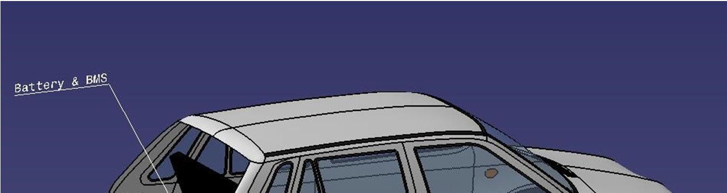
The battery is the essential part of the project as it will decide how much distance your vehicle will cover Batteries are basically collection of electrochemical cells which store the energy precisely electrical energy which can be used as per need. For our research we needed a battery which was light weight but also should be high energy dense also should have decent life cycles and less charging time. Hence lithium ion battery was the one which was most suitable for the job. A lithium ion battery is the battery which uses lithium as key component of chemical energy transfer.
TABLE 4
BATTERY SPECIFICATION
Nominal Voltage 3.6 V Full Charge 4.2 V Full Discharge 3 V
Minimal Voltage 2.5 V
Specific Energy 150 200 WH/KG Charge Rate 0.7 1 C
Discharge Rate 1C
Ideal Life Cycle 500 1000
Now by taking multiple cells according to required range we can connect them in parallel and series to achieve required power, current and voltage for the motor and other electronics.
ISSN: 2321 9653; IC Value: 45.98; SJ Impact Factor: 7.538
Volume 10 Issue XI Nov 2022 Available at www.ijraset.com
A battery management system allows users to monitor individual cells within a battery pack. As cells work together to release energy to the load, it is crucial to maintain stability throughout the whole pack. This is where a battery management system (BMS) comes into play. A BMS allows for constant monitoring, gathering, and communicating information to an external interface where users can observe the status of each cell and the health of the battery pack as a whole. The BMS monitors and manages a battery pack in order to protect it from damage, prolong its life, and keep the battery operating within its safety limits. These functions are key to efficiency, reliability, and safety.
Accelerator is a device which gives power input to engine but in electrical car there is there is a potential device which gives electrical signal called as potentiometer. Now as our vehicle will drive by ICE as well as electric motor and in hybrid mode it will be driven by both of them simultaneously. so, basically there will be two independent sources which will have two different separate throttles and it will be very inconvenient for the user and also it will not work while the vehicle is on hybrid AWD mode hence to overcome this problem, we have designed a new efficient as well as user friendly throttle which will control both ICE as well as electric motors.
This technology will be used in with hybrid mode of a car with multi cylinder IC engine. Main purpose of using this technology is to reduce fuel consumption and carbon footprint.
This system will be turned on when user/driver turns on hybrid mode in the vehicle. As soon as the hybrid mode will be turned on the Engine control unit (ECU) will analyze engine speed, vehicle speed and gear selected and will decide to shut off one of the cylinders or more cylinders in case of 4,5,6 or more cylinders IC engines.
As the need of power will be partially fulfilled by the electric motors, the engine can be run with low power and torque outputs by shutting of cylinder(s) and fuel can be saved as there will be no combustion taking place in that cylinder. This system will work as follows:
1) As soon as driver turns on hybrid mode, ECU will analyze power requirements by engine speed, vehicle speed and gear selected.
2) If power requirement is less than the ECU will shutoff cylinder(s) by closing the intake and exhaust valve and by cutting off the fuel supply to that cylinder(s)
3) The power requirement will be compensated by the electric motors hence reducing the fuel consumption and CO2 emissions.
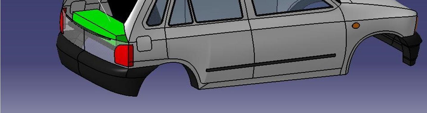
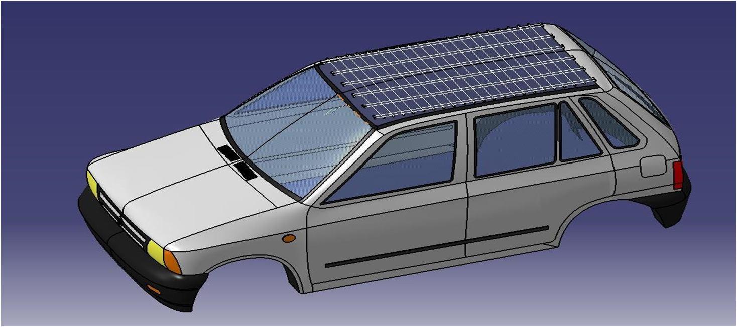
Solar energy is one of the most intense energy available for us. We have various technologies which can be used to harness the radiant light and heat from the sun and convert it into electrical energy. Solar energy is very crucial part of project as we are using the energy to charge the car and trying to make the vehicle a clean energy vehicle as well as making it free for the user for the daily usage like as already discussed that the average person in the city doesn’t use the vehicle for more than 25 km a day and most of the time the vehicle is parked. Hence it is our focus to charge the vehicle as much as possible from clean solar energy to allow the user to use it for free for at least 25 km in daily routine. Now the task was to place the photovoltaic cells on the vehicle without compensating the vehicle’s structural integrity and aesthetics and still generating enough power. Hence, we are going to use flexible thin solar panels which will be placed on the roof and bonnet of the car by taking proper precautions. The specifications of the panels are as below.


ISSN: 2321 9653; IC Value: 45.98; SJ Impact Factor: 7.538
Volume 10 Issue XI Nov 2022 Available at www.ijraset.com
Figure 7 Solar panel on roof
Environmental life cycle assessment of ICE & electric vehicles
TABLE 6 COMPARISON OF DRIVING EMISSION
Parameters
Car A (USED) Car B (NEW) Car C Hybrid Car
Energy Source Fossil Fuel Fossil Fuel Electric Hybrid Fuel Economy (KMPL) 10 14.9 Production Emissions (Kg CO2) 0 9000 10400 850 Driving Emissions (Kg CO2/Km) 0.400 0.286 0.125 0.175 Total Driving Emissions (KG CO2) 12000 mi/year
4800 3429 1500 2100
Total Emission Production +Drive 4800 12429 11900 2950
Referring the objectives of research, by adding some modifications the future scope of machine can be increased as follows:
1) Flexible solar panel can be installed for battery charging, that can bring the running cost of the vehicle to absolute zero.
2) Lithium ion battery can be installed for better range and weight reduction of the system.
3) This prototype is only for pure EV and Pure IC drive mode, in near future the development of vehicle can be done in such a way that hybrid mode can be played into the system thus increases the fuel economy of the vehicle running on internal combustion system.
4) Remote parking can be integrated into vehicle that can be useful when we have to remove the vehicle from tight space.
The progress that the electric vehicle industry has seen in recent years is not only extremely welcomed, but highly necessary in light of the increasing global greenhouse gas levels. the benefits of electric vehicles far surpass the costs. The biggest obstacle to the widespread adoption of electric powered transportation is cost related, as gasoline and the vehicles that run on it are readily available, convenient, and less costly. we hope that over the course of the next decade technological advancements and policy changes will help ease the transition from traditional fuel powered vehicles. Additionally, the realization and success of this industry relies heavily on the global population, and it is our hope that through mass marketing and environmental education programs people will feel incentivized and empowered to drive an electric powered vehicle. Each person can make a difference, so go electric and help make a difference!
ISSN: 2321 9653; IC Value: 45.98; SJ Impact Factor: 7.538 Volume 10 Issue XI Nov 2022 Available at www.ijraset.com
[1] P. Di Trolio, P. Di Giorgio , M. Genovese , E. Frasci, M. Minutillo A hybrid power unit based on a passive fuel cell/battery system for lightweight vehicles Applied Energy 279 Jan 2020 (115734)
[2] Yoshikazu Nishida,Naoki Maruno,Satoru Komoda: Battery Control Technology of Li ion Battery System for HEV The International Federation of Automatic Control September 4 7, 2013. Tokyo, Japan
[3] Thomas Nemeth,Jonathan Jansen,Cem Ünlübayir,Zhongbao Wei: Energy management of hybrid battery systems in electric vehicles Journal of Energy Storage (36) 2021
[4] Joao L. Afonso , Luiz A. Lisboa Cardoso ,Delfim Pedrosa,Tiago J. C. Sousa: A Review on Power Electronics Technologies for Electric Mobility MDPI Journal Energies Dec 2020
[5] Michel Broussely: Battery Requirements for HEVs, PHEVs, and EVs Elsevier B.V. 2010
[6] Kai Ni, Yihua Hu, Joseph Yan,Hui Xu: An Overview of Power Electronics Techniques in Electric Systems for Transport Applications International Journal of Research Studies in Electrical and Electronics Engineering 2017
[7] Fabio Orecchini1 Adriano Santiangeli , Alessandro Dell.: EVs and HEVs Using Lithium Ion Batteries Elsevier B.V 2014 8. Morris Brenna1,Federica Foiadelli,Carola Leone1:Electric Vehicles Charging Technology Review and Optimal Size Estimation Journal of Electrical Engineering & Technology (2020)
[8] Bilgin, P. Magne, P. Malysz, Y. Yang, V. Pantelic, M. Preindl, et al., "Making the Case for Electrified Transportation," IEEE Transactions on Transportation Electrification, vol. 1, pp. 4 17, 2015.
[9] Sarlioglu and C. T. Morris, "More Electric Aircraft: Review, Challenges, and Opportunities for Commercial Transport Aircraft," IEEE Transactions on Transportation Electrification, vol. 1, pp. 54 64, 2015.
[10] G. Sulligoi, A. Vicenzutti, and R. Menis, "All Electric Ship Design: From Electrical Propulsion to Integrated Electrical and Electronic Power Systems," IEEE Transactions on Transportation Electrification, vol. 2, pp. 507 521, 2016
[11] Chan, A. Bouscayrol, and K. Chen, "Electric, Hybrid, and Fuel Cell Vehicles: Architectures and Modeling," IEEE Transactions on Vehicular Technology, vol. 59, pp. 589 598, 2016