10 IX September 2022 https://doi.org/10.22214/ijraset.2022.46568
ISSN: 2321 9653; IC Value: 45.98; SJ Impact Factor:
10 Issue IX Sep 2022 Available at www.ijraset.com

ISSN: 2321 9653; IC Value: 45.98; SJ Impact Factor:
10 Issue IX Sep 2022 Available at www.ijraset.com

Abstract: By enabling in place and real time monitoring in daily life, intra body communication (IBC) is a cutting edge vital research topic that will promote customized treatment. In this study, data transmission over intra body networks is accomplished using the energy-efficient galvanic coupling (GC) technique. Two standard PCs with sound card support and Matlab software are used to create a novel sound card based GC testbed with the following key features: (i) low equipment requirements; (ii) high flexibility; (iii) real time physiological data transmissions; and (iv) nearly error free communication thanks to the development of specific physical (PHY) layer technology. Additionally, a signal to noise ratio (SNR) computation is suggested, serving as both a frequency offset compensation method and a statistic to assess the proposed design. The created GC testbed might be quickly copied by the interested research community to do simulation, encouraging more study in this area.
Keywords: Biomedical engineering, implantable devices, wireless sensor networks, intra body networks, intra body communication, galvanic coupling technologies, and coupling circuits.
In situ physiological testing, proactive medication administration, and tailored therapy will all be made possible by implanted sensors, which will revolutionize the future generation of healthcare. The Intrabody network (IBN) paradigm connects the implants and enables them to give orders to embedded actuators, get updates on the quantity of medication administration, and communicate measurements to an external Centre for real time processing and monitoring.
Ultrasound (US), inductive coupling (IC), capacitive coupling (CC), and galvanic coupling are examples of non RF approaches that employ the human body as a channel for data exchange (GC). We employ GC technology, in which a few electrodes are used at the transmitter and receiver to broadcast and receive low or medium frequency electrical currents (1 KHz 100 MHz) that are weak (1 mW) and directly connected to the tissue. Existing GC research define human tissues, examine variations in signal intensity in the tissues, and provide an invaluable foundation for investigating the viability of intra body communication methods.
The realization of an intra body data link between a transmitter and a receiver using several GC test methods has also been devised and put into practice. A testbed has been developed that uses a complex programmable logic device (CPLD) for the transmitter's digital signal processing modules, analogue units for the receiver's digital demodulation, and a field programmable gate array (FPGA) for the transmitter's analogue units. Recently, a baseband transmission using impulse radio (IR) and pulse position modulation was achieved on an FPGA board (PPM). In [9], a testbed is created that employs two universal software radio peripherals (USRPs), one at each of the transmitter and receiver, together with low frequency daughterboard.
US technology has lately been used to non RF intra body communication (IBC) systems [8]. US is made up of mechanical vibrations, whose energy travels through the substrate of interest from particle to particle as a wave. Since ultrasound demonstrates effective propagation across media mostly constituted of water, it has been widely employed in medical applications, such as in diagnostic imaging technology, as well as in underwater communications. Since the human body is composed of 65% water, it has been used for IBC [8]. Studies on ultrasonic communication have revealed that there is far less propagation loss in the body than there is for RF communications, leading to a potential IBC approach [3].
Another option to RF is inductive coupling (IC), which uses coils wrapped around a body part to transmit and receive magnetic energy [7]. When two wires are set up so that a change in current in one of the two wires generates a voltage across the ends of the other one by electromagnetic induction, the two wires are said to be inductively connected. By coiling two wires and placing them close to one another so that the magnetic field of one coil flows through the second coil, the coupling between the two wires is improved. It has been used mostly for data telemetry but also for wireless power transmission to implants [7].

ISSN: 2321 9653; IC Value: 45.98; SJ Impact Factor: 7.538 Volume 10 Issue IX Sep 2022 Available at www.ijraset.com
Numerous studies tested the mutual inductance of two linked coils and assessed the coupling strength, which is influenced by a number of variables including coil loading, excitation frequency, coil spacing, coil shape, coaxial alignment, and angular alignment [7]. The coupling efficiency, or the right resonance frequency matching between the transmitter and the receiver, is directly related to the data transmission efficiency and is not always simple to attain.
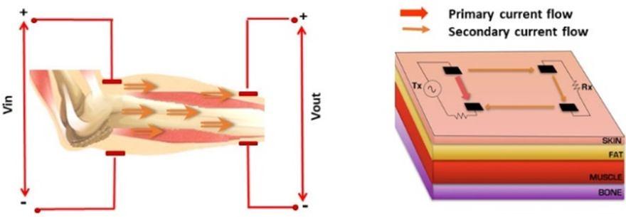
Two circuits that share an electric field constitute the foundation of capacitive coupling, which results in a transfer of energy from one circuit to the other [3]. One electrode at each of the transmitter and reception locations of the intra body CC system is connected to the body while the other electrode at each location is floating (the ground electrode simply has to be close by) [1]. The external ground serves as a signal return channel, while the body operates as a conductor of electric potential [3]. As a result, the route loss is greatly influenced by the surroundings, which is the fundamental disadvantage of CC but a benefit for IBC because it allows for extended internal distances [3]. Galvanic coupling technology is used for implant to implant communication. The human body is used by GC, like CC, to transmit an electrical signal produced by a few electrodes. However, unlike CC, GC does not require an external ground since both electrodes at the transmitter and receiver are linked to the body. A couple of electrodes that represent the transmitter receive an alternative current that is applied between them. While the primary current travels between them, other electrodes acting as the receiver may pick up secondary current routes travelling through the body.
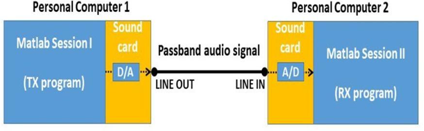
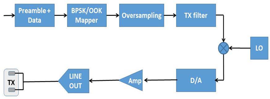
A GC platform with simple replication and PHY method implementation that can provide almost error free performance. On the basis of a PC sound card and the Matlab environment, we build and implement a GC testbed. Since the usual sound cards' permitted signal frequencies are included in the GC frequency range (1 KHz 100 MHz), we take advantage of this fact to create a straightforward platform that just needs two standard PCs with sound card compatibility and the Matlab programmed. Because it is simple to set up at low cost and the code is freely available online, the suggested testbed is therefore readily reproducible for the interested community and may also be used to build up a demonstrator of the exciting issue of intra body communication during lab courses by the students. To build the transmitter and receiver, respectively, two Matlab sessions must be launched on each PC, and the sound cards are utilized to provide actual signal transmission and receiving. Following that, the signal is sent from the PC to a biological tissue using a LINE IN/LINE OUT jack that is attached to the electrodes used to inject current into the tissue. The transmitter/receiver (tx/rx) Matlab programmed implement specific physical (PHY) layer techniques, such as modulation schemes and frequency, phase, and time recovery. A real time option for the receiver may be implemented through a Data Acquisition Toolbox (Daq/Tbx) in Matlab that takes advantage of the toolbox's real time data logging feature. This makes it feasible to transmit and evaluate physiological data sets in real time.
The suggested GC architecture's key advantages are its minimal equipment requirements and potential for nearly error free transmission. As shown in Fig. 2 and in the block diagram in Fig. 3, the first objective is achieved by using just two standard PCs with sound cards and the fundamental Matlab package for transmitter and receiver development. The second objective is accomplished by utilizing specific PHY techniques, such as the recovery of the carrier frequency, phase, and timing. In order to separate the common ground return pathways of the transmitter and receiver from GC technology during our testing, we use battery operated PCs disconnected from the grid.
International Journal for Research in Applied Science & Engineering Technology (IJRASET)
ISSN: 2321 9653; IC Value: 45.98; SJ Impact Factor: 7.538
Volume 10 Issue IX Sep 2022 Available at www.ijraset.com
The transmitter and receiver must be implemented using two separate Matlab sessions, one for each PC, as shown in Fig. 2. Real signal transmission and receiving are supported by sound cards in a limited frequency range by GC technology. Fig. 2 shows how the transmitted data are created in Matlab and transformed to analogue domain before being transferred via the transmitter's sound card. To send the signal outside of the PC, a cable is attached to the LINE OUT jack. The cable is attached to two electrodes that stand in for the GC transmitter, which transmits the signal over the tissue via GC communication technology, as will be explained later. The received signal is detected by the electrodes of the two receivers on the opposite side, and it is sent to the other PC through a cable attached to the LINE IN jack.
Figure 3. Block diagram of a GC application that takes into account a muscle that has a nerve compression disrupt its nerve signals.
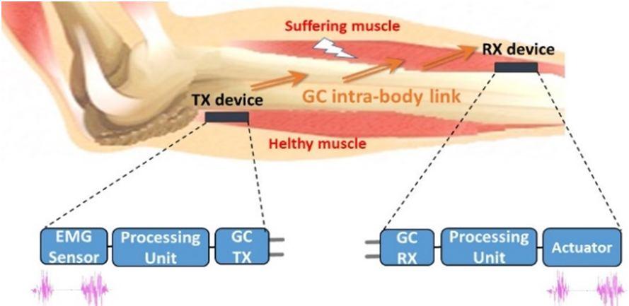
As a result, the receiver programmed in Matlab session II processes the data. The PHY system design's individual features are described in depth in the sections that follow. Because of the created carrier frequency recovery approach, we are able to produce almost error free transmission, which is a significant accomplishment for medical applications. As stated in the proposed application, it is essential to ensure a reliable communication when transmitting physiological data in order to, for example, obtain a precise monitoring of a patient in a critical condition or, as specified, to precisely replicate an EMG signal sensed in order to properly trigger another muscle.
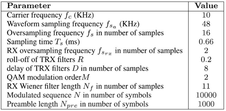
According to the selected modulation, the data are modulated in BPSK or OOK following bit creation, as shown in Fig. 4, creating a sequence ctx = ctxpre + ctxdata. The sequence ctx is routed to a squared root raised cosine (SRRC) filter after being oversampled by 16 as per Table 1's instructions. Thus, the matching baseband samples x (nTs), with n = 0, 1, . . . . , fs N 1, and sampling time Ts, are produced.
The resultant sequence is then multiplied by the cos signal, which stands for the local oscillator (LO) produced using software dene radio in the Matlab application, to up convert it to the carrier frequency. An audio passband broadcast signal results from this Stx:
Impact Factor 7.538
Impact Factor 7.894
Journal for Research in Applied Science & Engineering Technology (IJRASET)
ISSN: 2321 9653; IC Value: 45.98; SJ Impact Factor: 7.538
Volume 10 Issue IX Sep 2022 Available at www.ijraset.com
Where Tsa = 1/fsa with fsa = 48 KHz, whose value is set in accordance with the PC sound card's standard sample frequency, where fc is the carrier frequency. Considering the criteria stated in Table 1, Ts = 32 Tsa with a net data rate R = 1:5 kbs. To alter the necessary data rate, the parameters can be changed.
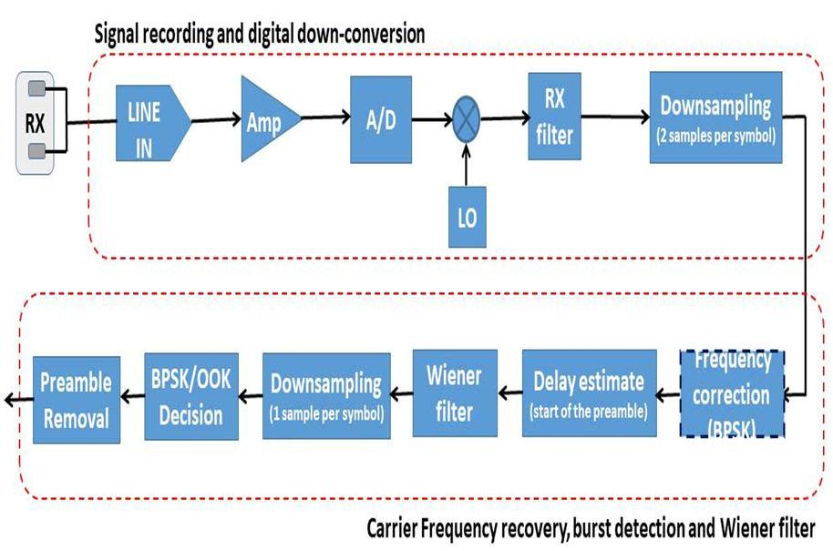
To launch the receiver application, which uses Matlab commands to record the received signal and save the data in the array, a Matlab session must be open in the PC linked with the GC receiver's electrodes srx According to Fig. 5, a digital down conversion is carried out by multiplying the received sampled signal srx by cos(2*pi*f'cn Tsa) and sin(2*pi*f'c nTsa), where f'c is the carrier frequency at the receiver, to obtain di(nTsa) and dq(nTsa), respectively. This is done after recording srx in digital format, which passes through. For BPSK, the sequence d(nTsa ) = di(nTsa ) + jdq(nTsa) is sent to an SRRC filter, resulting in a baseband received signal r(nTsa) with n = 1, . . . . fs N 1. Di and dj are separately routed to the SRRC filter for OOK, and its outputs are ri and rq. With the knowledge that the same process is applied individually to ri and rq in the case of OOK, we will simplify the notation in the following by referring solely to the signal r of the BPSK. OOK is not susceptible to frequency synchronization issues, although r of BPSK may be. Keep in mind that r also refers to the actual BPSK BB signal that comes from the SRRC filter, for which the prior down conversion is clearly not done. In order for the subsequent blocks to operate at two samples per symbol (fsrx=2, as described in Table 1), the output r is then decimated by eight. The sampled signal that was obtained may be represented as
Wherein n = 1. . . . . fsrx N 1, stx (nTs) is the passband signal's envelope sampled, v (nTs) is sampled additive white Gaussian noise (AWGN), and theta is random phase noise resulting from time delay.
A transmission receiver's performance is determined by a number of metrics, but SNR is particularly important since it directly influences how other metrics are judged [29]. The SNR estimate serves two purposes in this paper: it is used for both the frequency carrier recovery described in Sec. IV B2 and for the calculation of the probability of error in the experimental results, which helps to avoid conducting unnecessary experiments given that results that are almost error free under some circumstances. The procedures listed below are used to carry out the proposed SNR computation.
Factor
International Journal for Research in Applied Science & Engineering Technology (IJRASET)
ISSN: 2321 9653; IC Value: 45.98; SJ Impact Factor: 7.538
Volume 10 Issue IX Sep 2022 Available at www.ijraset.com
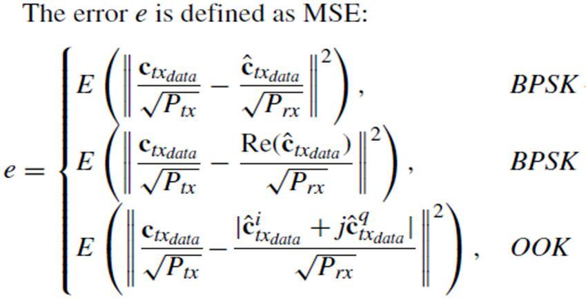
Ctx data is the sequence at the receiver that has been down sampled at one bit per symbol, and ctx data is the sequence at the transmitter following the BPSK/OOK mapper. Depending on the modulation that is being utilized, the definition of the error e varies somewhat.
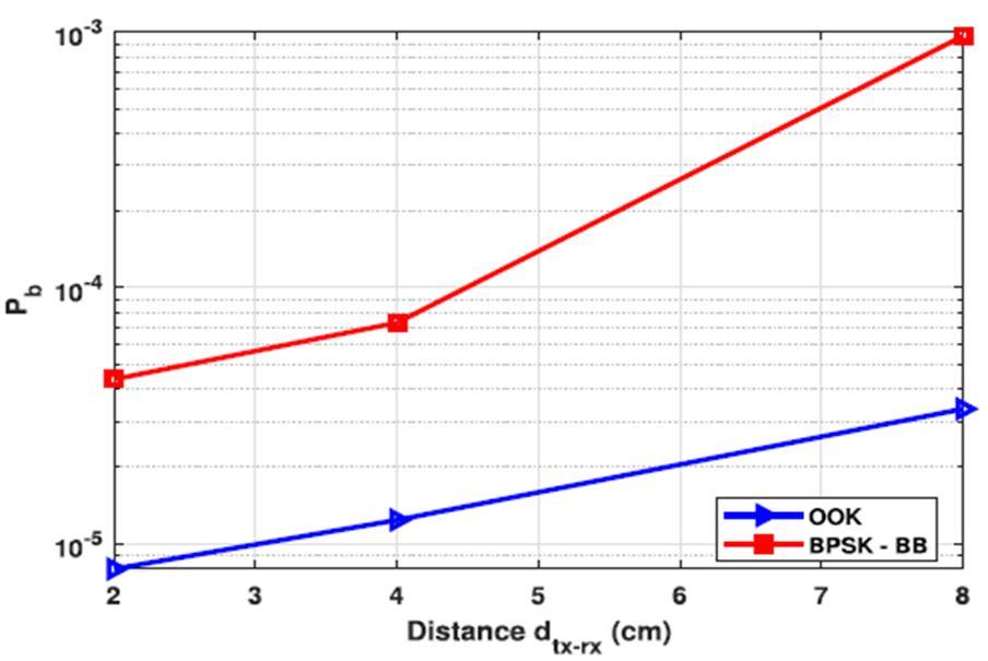
For transmitted data packets with length N equal to 1000 and Npre equal to 100, all approaches (BPSK, OOK, BPSK BB) display error free performance; however, for N = 10000 and Npre = 1000, BPSK degrades the performance due to the greater impact of the frequency offset error on longer sequences. When BPSK is given the frequency offset correction, this outcome is verified. In particular, with a frequency offset compensation of 1f in the range of a few units of Hz, performance is practically error free when N = 1000, however with N = 10000, error free performance is only possible if the frequency offset compensation is close to the true one, often about 2 Hz. The transmission power Ptx of BPSK with frequency offset correction has been evaluated in the range of 0.1 to 3 mW, yielding error free performance and an SNR of 18 to 21 dB. SNR is determined.
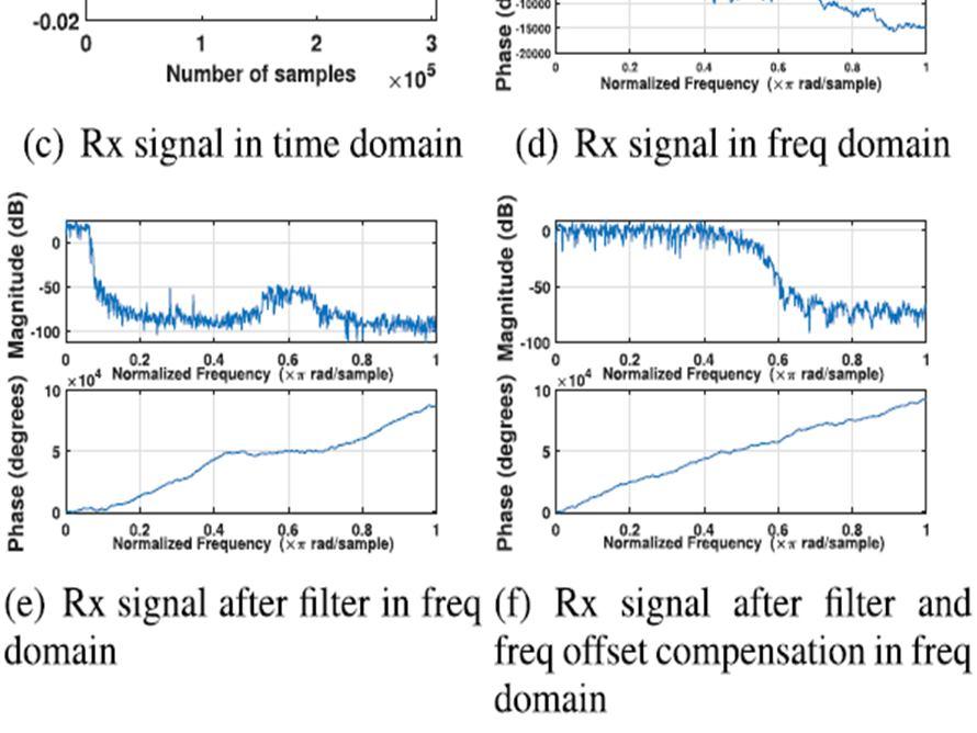
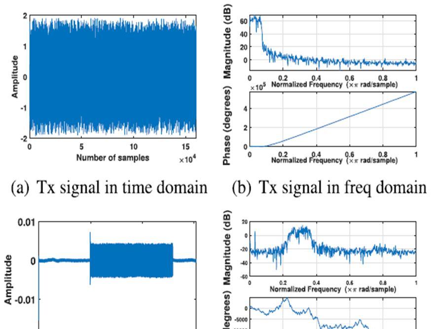
Figure 6. With BPSK modulation, both the signal being sent and received (distance between transmitter and receiver dtx rx=4 cm).
Here, a GC intra body links sent and received signal in time and frequency domain are shown using a qualitative analysis of the intended architecture. Then, a quantitative analysis is done in terms of SNR and error probability Pb. Here, we select BPSK as a potential modulation method. Figure depicts the sent and received signals at a distance of 4 cm between the transmitter and receiver and an inter electrode distance of 1:5 cm at both the transmitter and receiver. The received signal is shown at several stages, demonstrating the amplitude decrease between the sent and received signals as well as the distortion and compensation at the receiver. Both the time and frequency domains are taken into account. The signal's amplitude decreases as the distance between the transmitter and the receiver changes, as predicted. Particularly, the amplitudes of the received signal at 2, 4, and 8 cm are respectively two, three, and four orders of magnitude lower than those of the sent signal. In instance, Fig. 9 illustrates the received signals for various dtx rx distances in the frequency domain and demonstrates that, aside from an amplitude drop, the form of the signal remains the same between 2 and 4 cm, while a significant distortion develops at 8 cm but is rectified after filtering.
All Rights are Reserved | SJ Impact Factor 7.538 | ISRA Journal Impact Factor 7.894 |
& Engineering Technology (IJRASET
ISSN: 2321 9653; IC Value: 45.98; SJ Impact Factor: 7.538
Volume 10 Issue IX Sep 2022 Available at www.ijraset.com
Figure 7. BPSK modulated frequency domain received signal with variable dtx rx (distance between transmitter and receiver) values.
Evaluation of the proposed PHY architecture is done by comparing various modulation techniques (BPSK, OOK and BSK BB). We assess the equivalent SNR and then compute the probability of error Pb. In some circumstances, the strategies provided in the planned architecture enable to generate practically error free outcomes, which would need too lengthy tests for valid BER values. However, modulated BPSK requires frequency offset correction, in contrast to OOK and BPSK BB, but delivers almost error free performance, an important outcome for medical applications.
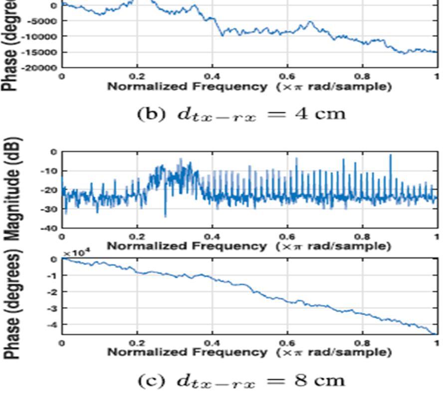
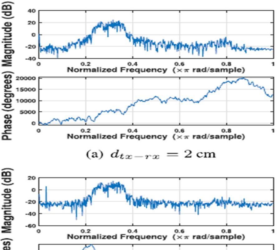
Figure 8. SNR varies with the dtx rx (distance between transmitter and receiver) distance.
Factor
Factor
International Journal for Research in Applied Science & Engineering Technology (IJRASET)
ISSN: 2321 9653; IC Value: 45.98; SJ Impact Factor: 7.538
Volume 10 Issue IX Sep 2022 Available at www.ijraset.com
As a rapid reproducible platform to conduct tests, we have suggested a sound card based GC testbed. The thorough explanation of the established test system should help interested researchers replicate the testbed and encourage more GC research as a result. The effectiveness of the suggested architecture has been evaluated through experimental tests for GC communication channels. With BPSK modulated signals and frequency offset correction, we achieve practically error free performance, which is a significant accomplishment in health applications. Additionally, we established SNR calculation as a metric to assess the efficacy of the suggested remedy. We want to conduct in depth tests in the future to assess the impact of the carrier frequency, bandwidth, audio sample frequency, and inter electrode distance at both the transmitter and receiver.
[1] M. Seyedi, B. Kibret, D. T. H. Lai, and M. Faulkner, ``A survey on Intrabody communications for body area network applications,'' IEEE Trans. Biomed. Eng., vol. 60, no. 8, pp. 20672079, Aug. 2013, doi: 10.1109/TBME.2013.2254714.
[2] B. Latré, B. Braem, I. Moerman, C. Blondia, and P. Demeester, ``A survey on wireless body area networks,'' Wireless Netw., vol. 17, no. 1, pp. 118, Jan. 2011.
[3] W. J. Tomlinson, S. Banou, C. Yu, M. Stojanovic, and K. R. Chowdhury, ``Comprehensive survey of galvanic coupling and alternative Intrabody communication technologies,'' IEEE Commun. Surveys Tuts. vol. 21, no. 2, pp. 11451164, 2nd Quart. 2019, doi: 10.1109/COMST.2018.2879643.
[4] M. S. Wegmueller, S. Huclova, J. Froehlich, M. Oberle, N. Felber, N. Kuster, and W. Fichtner, ``Galvanic coupling enabling wireless implant communications,'' IEEE Trans. Instrum. Meas., vol. 58, no. 8, pp. 26182625, Aug. 2009, doi: 10.1109/TIM.2009.2015639.
[5] M. A. Callejón, J. Reina Tosina, D. Naranjo Hernández, and L. M. Roa, ``Galvanic coupling transmission in Intrabody communication: A finite element approach,'' IEEE Trans. Biomed. Eng., vol. 61, no. 3, pp. 775783, Mar. 2014, doi: 10.1109/TBME.2013.2289946.
[6] M. Swaminathan, F. S. Cabrera, J. S. Pujol, U. Muncuk, G. Schirner, and K. R. Chowdhury, ``Multi path model and sensitivity analysis for galvanic coupled intra body communication through layered tissue,'' IEEE Trans. Biomed. Circuits Syst., vol. 10, no. 2, pp. 339351, Apr. 2016, doi: 10.1109/TBCAS.2015.2412548.
[7] M. S. Wegmueller, M. Oberle, N. Felber, N. Kuster, and W. Fichtner, ``Signal transmission by galvanic coupling through the human body,'' IEEE Trans. Instrum. Meas., vol. 59, no. 4, pp. 963969, Apr. 2010, doi: 10.1109/TIM.2009.2031449.
[8] M. J. Seyedi and D. Lai, A Novel Intrabody Communication Transceiver for Biomedical Applications. Singapore: Springer, 2017.