10 XII December 2022 https://doi.org/10.22214/ijraset.2022.47901
ISSN: 2321-9653; IC Value: 45.98; SJ Impact Factor: 7.538 Volume 10 Issue XII Dec 2022- Available at www.ijraset.com

ISSN: 2321-9653; IC Value: 45.98; SJ Impact Factor: 7.538 Volume 10 Issue XII Dec 2022- Available at www.ijraset.com
Prof. M. S. Shelke1 , Arpit Umare2 , Kunal Bhongade3 , Krutika Ambade4 , Payal Jiwane5 1K.D.K. College of Engineering, Nagpur
Abstract: The aim is to design and analysis of a chassis. A chassis design involves selecting optimum measures of parts and iterating it to achieve the objectives assumed. Every part of chassis is related to each other; it is necessary to study effects to get optimum design. Mild steel is a ferrous metal made from iron and carbon. Various formulas were used and we have to satisfies all the objectives in the beginning.
Keywords: chassis, design, ergonomics, fixtures, FSAE, total deformation, equivalent stress, formula one, safety, flags, equipment, regulations.
This project aims to design new FSAE (formula society of automotive engineers) chassis for the 2022 session The development of low-cost fixtures compared to high-cost conventional metal fixtures. The design and constructions are framed according to the human relations with the vehicle. The purpose is to design frame chassis that should be strong enough to absorb the energy when front, back, side, torsional loads are applied. The chassis must be able to accommodate and support all the components of the vehicle and any occupants and must absorb all loads without excessive deflection. The chassis must be rigid in both torsion and bending and must be able to resist twisting and sagging. The function of the chassis is to protect the driver and support front and rear suspension system, engine, drive train, steering system and other systems in the vehicle. During the design process, we must achieve a compromise between cost, manufacturing, performance, and design time so that the car will be competitive in all aspects.

By progressing towards using more sustainable sources of energy to power vehicles, the automotive industry can be a major leader in the progress towards sustainable energy practices and cleaner energy technologies. Already, significant progress had been made in the electric vehicle industry led by newly formed automotive ventures such as Tesla Motors, Lightning Car Company, and Detroit Electric. Automobile giants such as FORD, GM, TOYOTA, MERCEDES, AUDI and even FERRARI have also implemented research and development efforts in the clean vehicle sector with the likes of the volt, prius and many more.
The desire outcome of the battery pack was to have the most powerful energy source allowed by the SAE competition rules. A series of system requirements were developed that would allow the team to quantity the project goals and constraints. Both the voltage and power requirements also represent the maximum values allowed by the competition. The design should be made not to compromise driver safety at any condition. The cockpit design is essential, as it has to accommodate the 95% male.
The paper gives insight into the analysis concepts about loading and boundary conditions. The CAD model of chassis were analyzed by using cad software(solidworks). All possible views were analyzed and Torsional stress analysis, torsional deflection analysis, torsional analysis boundary conditions, etc. were analyzed.
The material with low cost high strength and good weld ability must be used . After the extensive paper study of different material, we concluded to decide between SAE 1018 and SAE 4130. Alter discussion and analysis considering the physical strength, weight, availability and cost of the material we decided to use AISI 4130 as material.

Properties
ISSN: 2321-9653; IC Value: 45.98; SJ Impact Factor: 7.538 Volume 10 Issue XII Dec 2022- Available at www.ijraset.com
AISI 1018 AISI 1020 AISI 4130
% carbon 0.14 - 0.20 0.17 - 0.23 0.28 - 0.33
Density(g/cc) 7.87 7.87 7.85 Modulus of Elasticity(GPa) 200 200 205
Yield strength(MPa) 365 294.74 435 Ultimate Strength(MPa) 450 394.72 670 Bulks Modulus 140 140 140 Poisson’s Ratio 0.29 0.29 0.29
Elongation at Break 15% 15% 25.50%
The material used in designing and development of this project is AISI 4130. This steel provides necessary strength. This metal combines both iron and carbon elements along with manganese, sulphur chromium and silicon. Due to its versatile properties it is dominating in the current market. It is so useful that the American iron & steel industry and Society of Automotive Engineers (SAE) outlined numerous grades of steels which are made for specific purposes and denoted by 3 to 5-digit identifiers. 4130 is commonly used alloy steel. The chassis material is considered depending upon the various factors such as maximum load capacity, absorption force capacity, strength and rigidity. The material selected for the chassis building is AISI 4130. AISI 4130 is a alloy/low steel. The material used in designing and development of this project is AISI 4130. This steel provides necessary strength. This metal combines both iron and carbon elements along with manganese, sulphur chromium and silicon. Due to its versatile properties it is dominating in the current market. It is so useful that the American iron & steel industry and Society of Automotive Engineers (SAE) outlined numerous grades of steels which are made for specific purposes and denoted by 3 to 5-digit identifiers. 4130 is commonly used alloy steel. The chassis material is considered depending upon the various factors such as maximum load capacity, absorption force capacity, strength and rigidity. The material selected for the chassis building is AISI 4130. AISI 4130 is a alloy/low steel.
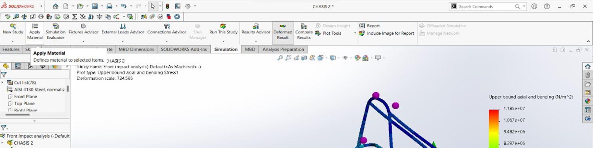
Front Impact Analysis : Front impact analysis is performed to check the deformation of chassis while load is acting on frontal side of chassis. In this test , the rear side of chassis is kept fixed ( shown by green arrows in fig.4.1) and the force is acting on front side of chassis ( shown by orange arrows in fig.4.1.).
ISSN: 2321-9653; IC Value: 45.98; SJ Impact Factor: 7.538 Volume 10 Issue XII Dec 2022- Available at www.ijraset.com
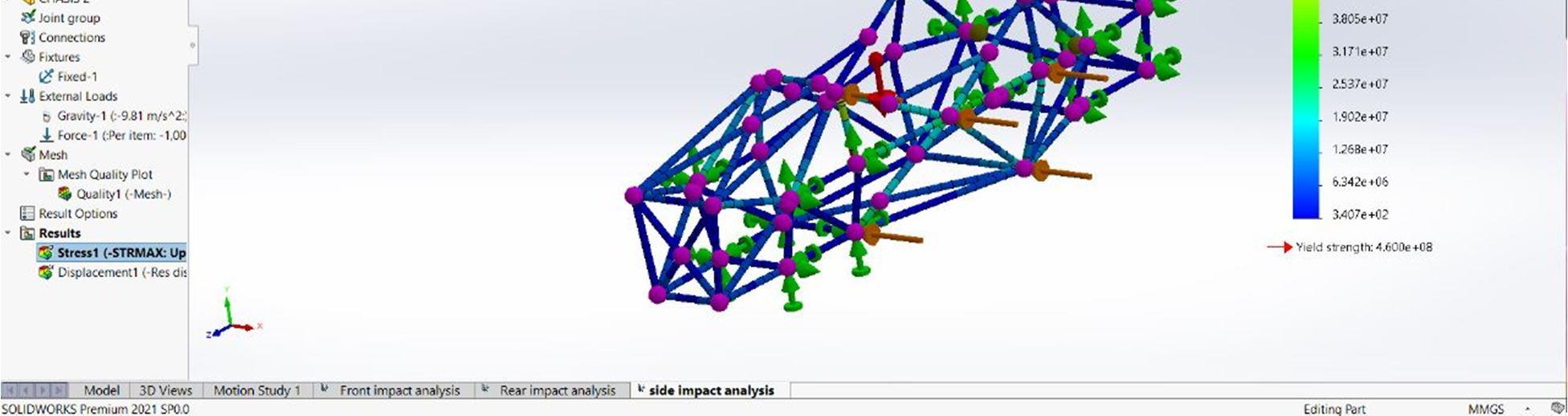
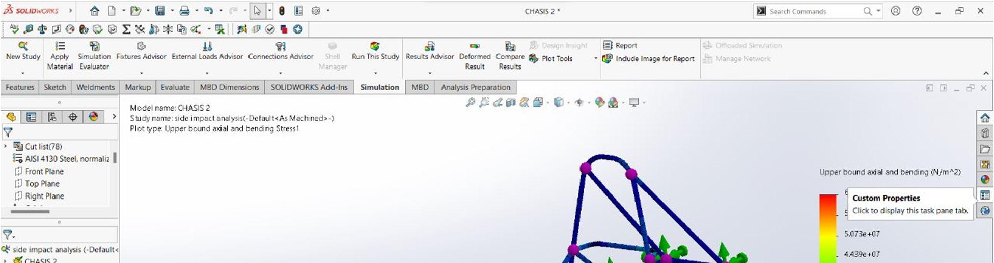
Side Impact Analysis: This test is performed to check the deformation of frame when the load is acting on either of the sides. The front and rear sides of chassis is kept fixed ( shown by green arrows in fig.4.2.) and the load is applied on sides(shown by orange arrows).
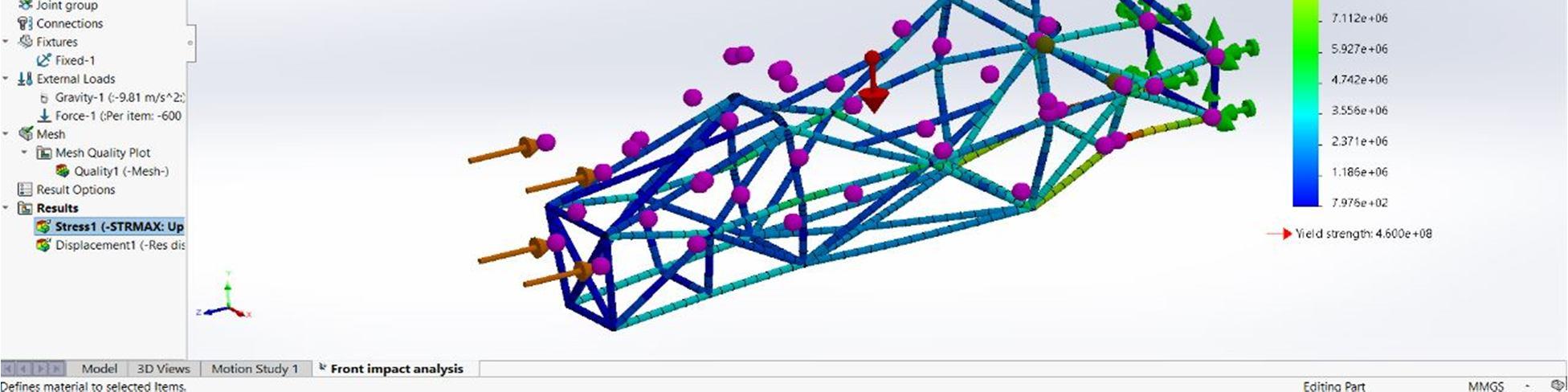
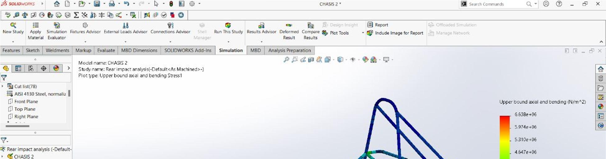
Rear Impact Analysis: Rear impact analysis is similar to front impact analysis with the difference that in the case of rear impact analysis front portion of frame is kept fixed and the force is applied ion read side of frame.(shown in fig.4.3).
Torsional Analysis: Torsional analysis involves the twisting of frame along the axis and it is useful test for acquiring information like torsional shear stress, maximum torque, shear modulus, and breaking angle of material.
ISSN: 2321-9653; IC Value: 45.98; SJ Impact Factor: 7.538 Volume 10 Issue XII Dec 2022- Available at www.ijraset.com
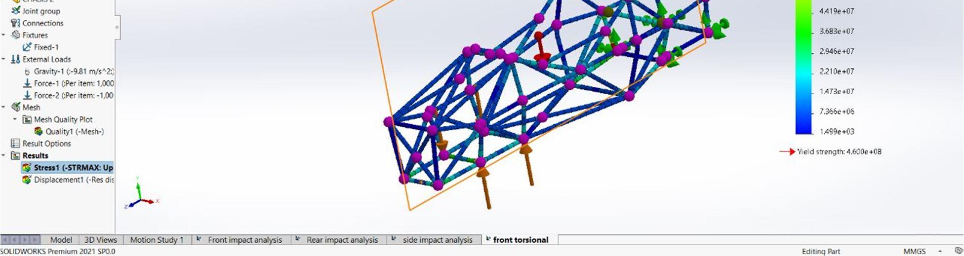
In front torsional analysis the rear side of frame is kept fixed and equal and opposite load is acting on front portion of frame which causes the frame to twist along its axis . Similarly, in rear torsional test the front side of frame is kept fixed and and the force is acting on rear side of frame.
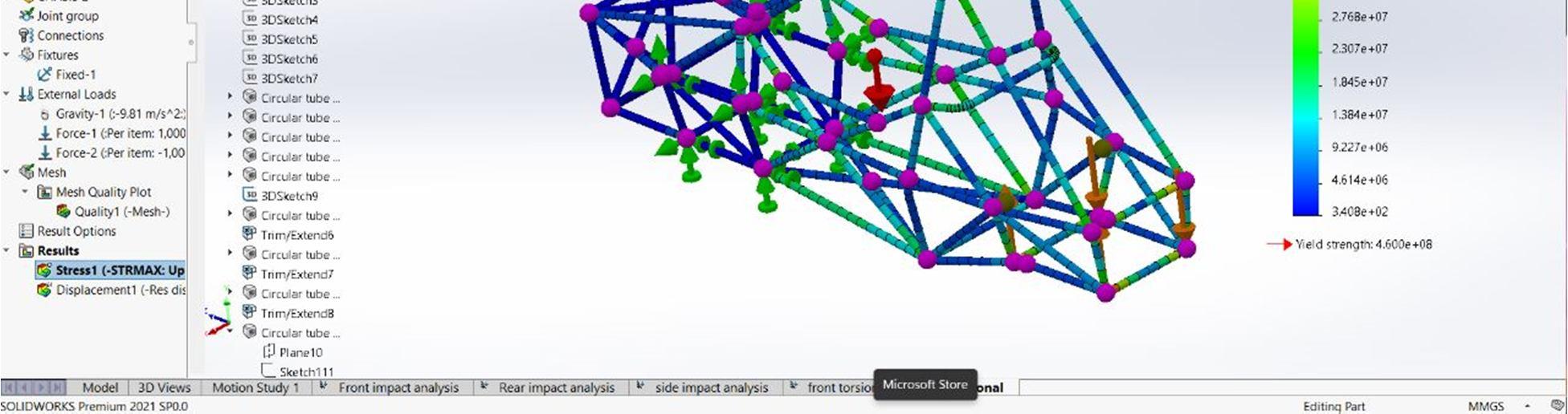
Fig.4: Front Torsional Analysis
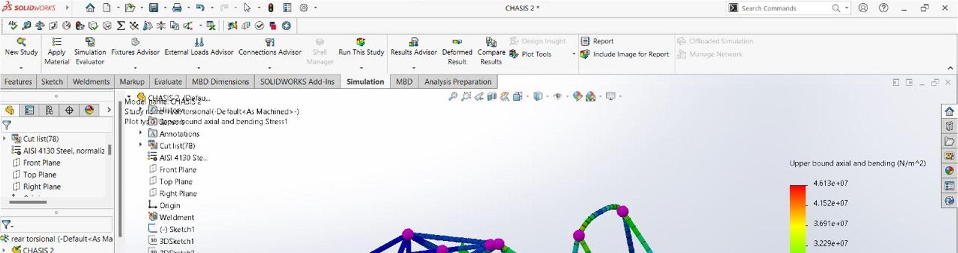
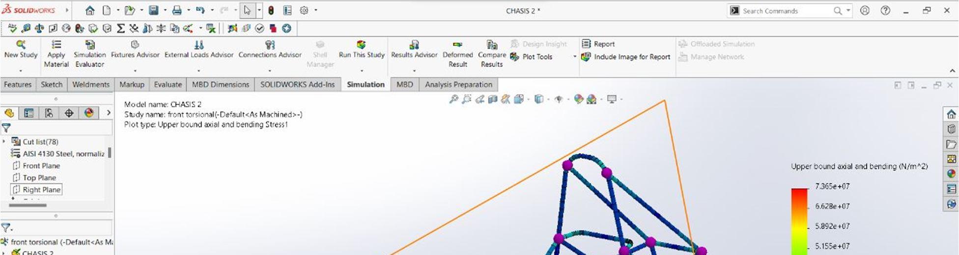
Fig.5: Rear Torsional Analysis
The design of chassis satisfies all the objectives decided at the beginning. Because of the kind of fixture developed, it saves lot of manufacturing investment in steel fixtures. Physical ergonomics gives crucial data about the positioning of different components and visibly aspect to a driver before complete manufacturing and assemblage of vehicle.
ISSN: 2321-9653; IC Value: 45.98; SJ Impact Factor: 7.538 Volume 10 Issue XII Dec 2022- Available at www.ijraset.com
Initial results of the system have yielded great promise in reach of our power and efficiency goals. Construction of battery pack has progressed rather smoothly with minor to zero issues encountered The slider package has proved robust, although minor adjustments are being made in order to deal with the differentiation between the predicted length of level one of the battery pack and the actual size.
[1] “DESIGN AND SIMULATION OF ELECTRIC CAR CHASSIS” , by Arjun Singh,Aditya Tiwari, Shubham Kalsa,Asheesh Kumar, Akshay Kant,IJDER 2016, vol.6
[2] Saurabh Sirsikar, Ajay Bhosale, Akshay Kurkute, Sumedh Ghawalkar, Ketan Sahane, “ REVIEW ON DESIGN, ANALYSIS AND FABRICATION OF RACE CAR CHASSIS”, International Research Journal of Engineering and Technology, vol.7, 3 March 2020
[3] “DESIGN OF FORMULA STUDENT RACE CAR CHASSIS”, by Abhijeet Das, 2013 , International Research Journal of Science and Technology.
[4] “ANALYSIS OF FORMULA STUDENT RACE CAR”, by B. Subramanyam, Vishal, Mahesh Kollati, K.Praveen Kumar, published by International Journal of Engineering Research and Technology,vol.5,10 oct 2016
[5] Ameya Dabhade, Khizar Pathan,Sher Khan, Akash Jadhav,” DESIGN AND DEVELOPMENT OF CHASSIS FOR FORMULA STUDENT CAR” International Journal of Advance Research in Engineering and Technology, vol.11 10 Oct 2020
[6] “DESIGN ANALYSIS OF CHASSIS USED IN STUDENT FORMULA RACING CAR USING FFA TOOL”, by Amogh Raut and Aniket Patil,vol.7 1 Oct 2017, International Journal Of Engineering And Advance Technology
[7] Mohd. Tazeem Khan, “ DESIGN AND MANUFACTURING OF FEAE CHASSIS”,International Journal of Modernisation in Engineering Technology and science vol.3 2/2/2021
[8] “FORMULA ONE SAFETY: A REVIEW”,by Shubham Ugle, Shweta Kate and Dhananjay Dolas, published by International Research Journal of Engineering and Technology, vol.2, 7 Oct 2015
[9] “FORMULA ELECTRIC SYSTEM: A DESIGN AND INTEGRATION”,by Mark Allison, Kevin Claggett, Stuart Hopson, Dominic Villa, Abdlomnen Beitelmal, Timoti Hight, by International Mechanical Engineering Congress and Exposition, Nov 2013
[10] Satish Kumar Chhitaliya , Het Anghan, Utsav Vaghani, “A METHODOLOGICAL STUDY TO ANALYZE AND DESIGN THE CAR CHASSIS” by International Journal for Research in Applied Science and Engineering Technology,vol.9 12 Dec 2021