
10 VII July 2022 https://doi.org/10.22214/ijraset.2022.44893

Abstract: In this project design, fabrication, and analysis of sheet laminated Metal Matrix Composites will be carried out. It will be very useful for Aircraft Nose Cone, drone frames, and other surface materials of aircraft. The model of laminated metal matrix composite is designed using Catia V5 and also material to be applied to the body. Imported Geometry from Catia V5 to ANSYS will be analyzed by applying material properties and loads under different conditions. Based on ANSYS results the laminated metal matrix composite will experiment with. In that I take there are three types of Combinations of Laminated Metal Matrix Composites
1) Top and Bottom Aluminum Plate between Carbon fiber (aluminum top 1mm bottom 1mm +carbon 0.5 mm= 2.5mm thickness), 2) Top, Bottom, and Middle Aluminum in between Carbon fiber (aluminum (1+1+1)3mm + carbon 1mm= 4mm thickness), and 3) Top and Bottom Carbon and Middle Aluminum (Carbon (0.5+0.5) 1mm +aluminum 1mm =2mm thickness) which means 25%, 33%, and 50 % of carbon reinforced into aluminum metal.
Keywords: Laminated Metal Matrix Composite, Drone Frame I. INTRODUCTION
Enhanced stiffness and strength are two primary driving reasons for Metal Matrix Composites. With a density of 1.55 g/cm3, carbon is a highly light and durable element that can take on many different shapes. With a specific weight of 2.7 g/cm3, aluminum is a fairly light metal. Aluminum is extremely corrosion resistant and naturally produces a protective oxide covering. Metal matrix composites (MMCs) are made of at least two chemically and physically different phases that are evenly dispersed to provide characteristics that are not possible with any one phase alone. There are typically two phases, such as a fibrous or particle phase that are properly dispersed across a matrix. There are four different types of continuous alumina fibers, which are utilized in an aluminum matrix composite for power transmission lines, as examples. There are four kinds of MMCs: Particle reinforced MMCs, Short fiber or whisker reinforced MMCs, Continuous fiber or sheet reinforced MMCs, Laminated or layered MMCs Metal matrix composites have assumed special importance because of the following reasons: Compared to continuous fiber reinforced composites, particle reinforced composites are less expensive. Cost is a crucial factor for high utilization rates, any processing involving casting or powder metallurgy can be used, followed by normal second stage processing, Higher use temperatures are possible than with the unreinforced metal, Enhanced modulus and strength, increased thermal stability, better wear resistance, relatively isotropic properties compared to those of the fiber reinforced Composite. This research uses software and real time experiment testing to analyze the strength, flexibility, and breaking points. The goal of the current study is to identify a good weight to strength ratio. Due to its exceptional specific strength property, metal matrix composites (MMCS) have grown in popularity as an alternative to conventional materials, particularly in the automotive, aerospace, and defense sectors. MMCS are particularly desirable for engineering structural applications. A carbon matrix and carbon particles serve as reinforcements in the carbon MMC, which has numerous favorable mechanical characteristics. In this work, an effort has been made to create MMCS II. OBJECTIVE This project analyzes the strength, elasticity, and Breaking points using software and real time experiment testing. In the present study Main theme is to find a good weight to strength ratio. Metal matrix composites (MMCS) have become attractive for engineering structural applications due to their excellent specific strength property and are increasingly seen as an alternative to conventional materials, particularly in the automotive, aerospace, and defense industries. Carbon MMC has an aluminum matrix and Carbon particles as reinforcements and exhibits many desirablemechanical properties. In the present study, an attempt has been made to fabricate MMCS
Experimental Investigation of Laminated Metal Matrix Composite Used in Drone Frame
International Journal for Research in Applied Science & Engineering Technology (IJRASET) ISSN: 2321 9653; IC Value: 45.98; SJ Impact Factor: 7.538 Volume 10 Issue VII July 2022 Available at www.ijraset.com 4545©IJRASET: All Rights are Reserved | SJ Impact Factor 7.538 | ISRA Journal Impact Factor 7.894 |
M. Karthikeyan1 , S. Karthik2 , Dr. P. Karunakaran3 , Dr. M. Gowtham4 1M.E., Aeronautical Engg, Student, 2, 3, 4Assistant professor Dept Of Aero Engg., Excel Engineering College, Namakkal, Tamilnadu.


Florea Raluca Maria [1] From the study host resin matrix is a significant aspect that influences the final multilayer laminate's toughness. The final laminate is the toughest when the underlying resin toughness is greater. However, the percentage increase in GIIC brought on by the development of the multilayer structure is mostly independent of the maximal toughness increases of the base resin, which are equal to about 100%. Additionally, the site of crack propagation during testing directly correlates with the reported toughness improvements. Toughness increases might be anticipated if fracture propagation takes place in the interlaminar area. However, toughness may be compromised if the break propagates into the intralaminar area. To balance interlaminar and intralaminar fracture toughness, the quantity of toughness enhancement must be increased. Last but not least, this investigation has shown that despite the layered structure.Jenix Rino1 [2] The stir casting technique may be used to successfully create the investigated Aluminum alloy matrix composites reinforced with Hybrid. The stirrer design and position, stirring speed and time, melting and pouring temperature, particle preheating temperature, particle incorporation rate, mold type and size, and reinforcement particle size and amount are crucial process parameters for the stir casting method used to create hybrid composites. The hardness, toughness, strength, corrosion, and wear resistance of the composite will be further increased with the use of hybrid reinforcement rather than single reinforcement. Aluminum alloys are used extensively in the aerospace and automotive industries because they are less dense than conventional metals and alloys, have high mechanical qualities, are better at resisting corrosion and wear, and have a lower thermal coefficient of expansion. The superior mechanical attributes Sudipt Kumar, et al. [3] The study's findings suggest that fly ash can be used to make composites, converting industrial waste into financial gain. Additionally, this can address the issue of fly ash storage and disposal. By using the stir casting method, fly ash up to 10% by weight can be successfully added to aluminum to create composites. With the addition of 10% fly ash, pure Al's hardness increased from 16 BHN to 18 BHN. Additionally, the density of the Al melts decreased noticeably when fly ash was added, going from 3.398 gm/cm3 to 2.807 gm/cm3. With the addition of fly ash to Al melt, both the friction coefficients and the wear rates significantly Suryanarayanandecreased.K[4]
Nikhilesh Chawla Krishan K et al. [6] Investigated the employment of particularly creative systems, notably in the domain of light metals, which has not been achieved despite inspired rising development activities leading to system solutions using metal composite materials. This is due to insufficient economic efficiency, production and processing issues, and process stability and reliability issues. The industry is unwilling to pay extra expenditures for the usage of such sophisticated materials in application areas like traffic engineering because these fields are particularly cost conscious and cost J.Anandaoriented. Theerthan [7] In this experimental study it is found that as the sintering temperature rises, the MMC's density and hardness qualities also improve. The investigational MMCs' mechanical characteristics, such as density and hardness, are dependent on both the SiCp weight percentage and mesh size. Hardness and density are both increased by heat treatment after sintering. As the SiCp reinforcement, weight percentage, and mesh size rise after heat treatment, so does the percentage of density. After heat treatment, the percentage of hardness increases with weight percentage but decreases with a mesh size of SiCp. It has been determined that the characteristics are affected by heat treatment after sintering. As SiCp rises, the density rises as well. With increasing SiCp weight percentage in the composite and mesh size, MMC's hardness rises.
International Journal for Research in Applied Science & Engineering Technology (IJRASET) ISSN: 2321 9653; IC Value: 45.98; SJ Impact Factor: 7.538 Volume 10 Issue VII July 2022 Available at www.ijraset.com 4546©IJRASET: All Rights are Reserved | SJ Impact Factor 7.538 | ISRA Journal Impact Factor 7.894 | III. LITERATURE REVIEW
certain requirements must be satisfied before any material can be employed in aerospace applications. Although the precise set of required attributes varies depending on the particular application, some characteristics, such as low density, superior fatigue performance, and high wear and corrosion resistance, are regarded as essential for the industry to operate effectively. Therefore, by examining its qualities, this study builds a case for Al SiC MMC and its use in the aerospace sector. The material's low density and strong wear (and corrosion) resistance were two of the primary considerations. It is clear from the literature that these materials can be produced using either solid phase or liquid phase techniques. However, this work suggests the latter as they tend to Second Edition Nikhilesh Chawla Krishan K. [5] The Metal matrix composites (MMCs) under investigation are made up of at least two chemically and physically different phases that are adequately dispersed to provide characteristics not possible with/or with any one of the phases alone. There are typically two phases, such as a fibrous or particle phase that are properly dispersed across a Formatrix.superconducting magnets, continuous alumina fibers in an aluminum matrix composite, Nb Ti filaments in a copper matrix, tungsten carbide (WC)/cobalt (Co) particulate composites for cutting tools, and oil drilling inserts are a few examples.
International Journal for Research in Applied Science & Engineering Technology (IJRASET) ISSN: 2321 9653; IC Value: 45.98; SJ Impact Factor: 7.538 Volume 10 Issue VII July 2022 Available at www.ijraset.com 4547©IJRASET: All Rights are Reserved | SJ Impact Factor 7.538 | ISRA Journal Impact Factor 7.894 | Johny James.S [8] Investigated the distribution of SiC and TiB2 in the metal matrix as revealed by the microstructural study. Cluster formation is caused by an increase in the weight percentage of reinforcement (SiC 10% and TiB 25%). As a result, the maximum percentage of TiB2 in the matrix is restricted to 2.5% for 10% SiC.
Based on measurements of hardness, it has been determined that while the addition of reinforcements influences hardness value, the addition of TiB2 up to 5% results in porosity, which impacts hardness value. According to the results of tensile tests, adding reinforcement SiC to base metal increased the composite's strength by 20%, however adding TiB2 resulted in a 50 60% drop in strength. After the experiment, the microstructure study and the tensile specimen were examined.
• When compared to its base value, the hardness and tensile strength values are higher when activated carbon is used in the AA7075 matrix. Because of the growing level of reinforcement, there is an associated high change improvement in durability and elongation. The quality of the AA7075 PAC composites was subsequently expanded by adding more reinforcement.
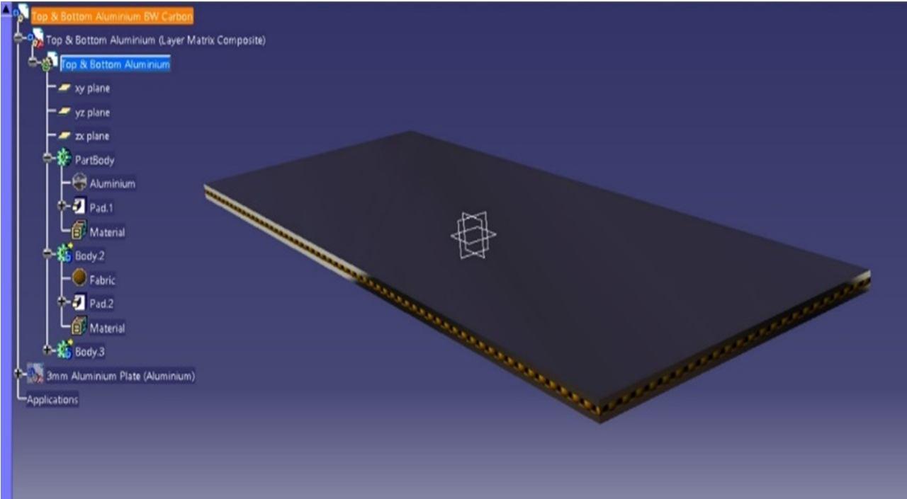
A. Cad Modeling That design has three layers and each layer is 1mm to find which combination goes to be a better one. The fabric and aluminum are applied in that designed model. 1) Top and Bottom Aluminum Plate between Carbon fiber and 2) Top and Bottom Carbon and Middle Aluminum. CATIA offers several applications/workbenches such as part design, assembly design, drafting, sketcher, wide frame and surface, and others. The interfaces of these applications are somewhat similar to each other. The part design application is used in the creation of precise 3D models of machine parts. I’m designed the top and bottom aluminum plates using CATIA v5 tools and also material applied both the parts Fig 1.1 Top and Bottom aluminum in between carbon fiber
Assoc. Prof. Dr. Prusov E.S. [9] Proposed According to the operational circumstances of the components of friction units, the primary materials requirements for tribological objectives have been systematized. It has been suggested to use the general principles of alloys design theory to choose the best alloying and reinforcing complex compositions of composite alloys for tribological objectives. Application of the suggested methodological approach enables suitable selection of metal matrix composite alloys components under conditions of various reinforcing schemes, such as exogenously reinforced, endogenously reinforced G. Ramanan [10] Following a thorough examination of the mechanical properties of AA7075 three various wt percent of PAC composite successfully produced by stir casting process, the following results were made:
In Catia select the part design and made a rectangle in that dimension of 145mm x 58mm thickness of 1mm each layer made three layers of the part body separately each layer needs to apply the material. After the material is applied the part design color will be changed you can visually see those chances
B. Ansys Material Applied In Ansys predefined material is structural steel, need the choose another material to apply to those laminates. In that experiment I applied 1) Top and Bottom Aluminum Plate between Carbon fiber and 2) Top and Bottom Carbon and Middle Aluminum 1) which means 33% aluminum and 66 % carbon reinforced into laminated Metal matric composite and 2) similarly 66% aluminum and 33% carbon reinforced into laminated Metal matric composite. The material to be applied on the top and bottom layer of laminate metal matrix composite
1) Static structural >Engineering data source >remove structural steel >add Aluminum alloy and Epoxy carbon > Exit from Engineering data Source Fig 1.3 Material Applied in Ansys
International Journal for Research in Applied Science & Engineering Technology (IJRASET) ISSN: 2321 9653; IC Value: 45.98; SJ Impact Factor: 7.538 Volume 10 Issue VII July 2022 Available at www.ijraset.com 4548©IJRASET: All Rights are Reserved | SJ Impact Factor 7.538 | ISRA Journal Impact Factor 7.894 |
Fig 1.2 Ansys Material Selection Fig 1.2 the diagram shows the material selected in that Ansys. In Ansys, structural analysis steel is the default material selected by the software we need to change the material to what we want. In that experiment, we need to choose the aluminum alloy and Epoxy carbon.
The fig 1.3 diagram shows the selected material applied in that imported model based on our experiments. The top and bottom are aluminum between carbon fiber
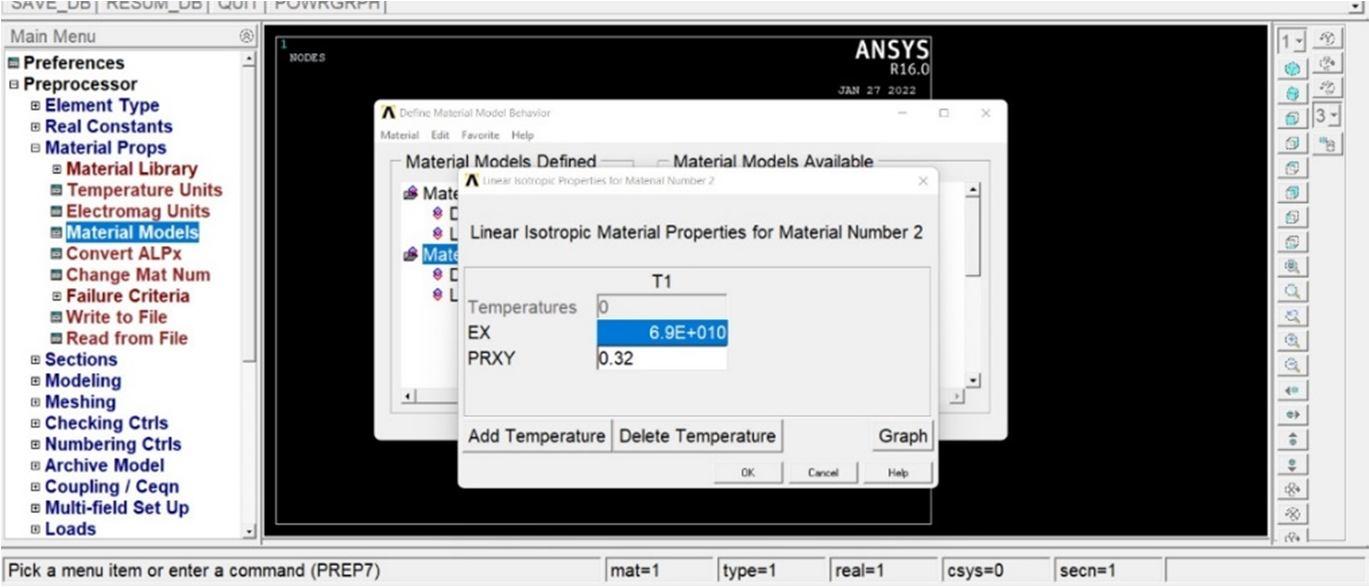
2) Project > Model >Geometry > import external Catia Model >Generate >Apply martial along with your type Above the process do in Ansys C. Youngs Modulus Poisson’s Ratio and Density Applied in Ansys Mechanical APDL If I Analysis in Mechanical ADPL you can get a different material property based on that material strength will be decided. That is for this amount of strain Aluminum: 0.31 elastic modulus (E) Apply a Displacement of detail such as 0.0003 m in the X direction. Obtain the Reaction Force for this displacement in N force. Divide the Stress by the Strain to get Young's Modulus in Pa for this Specimen APDL Ansys parametric design language.
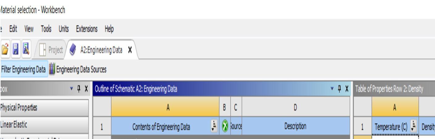
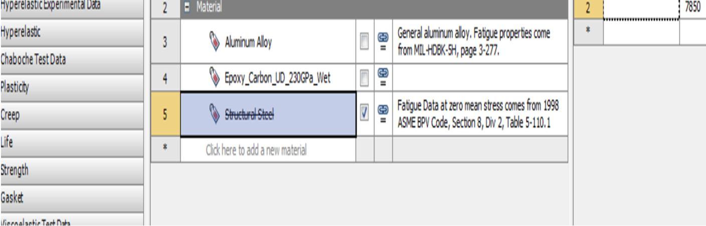
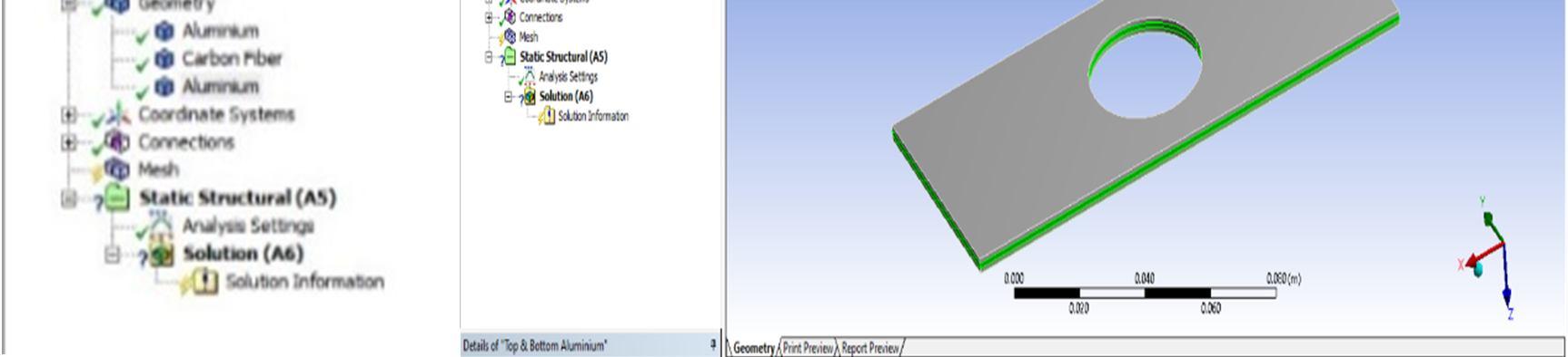
Fig 1.4 Aluminum young’s modulus and passion ratio apply
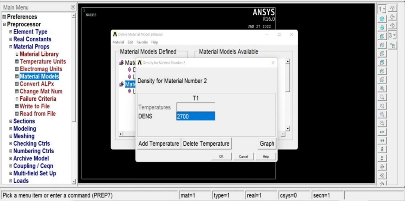
2) Ansys Mechanical ADPL >Material Prop >Material Model Defined >Dens (Material Number 2). Need to follow the above steps to be applied in the density of material number 2. Similarly, material number 3. Fig 1.5 Aluminum density applied Fig 1.5 shows the dens applied in that Ansys based on that the property will be derived. The carbon also has density, Poisson’s ratio, and young’s modulus should be applied.
1) Ansys Mechanical ADPL >Material Prop >Material Model Defined >Linear isotropic material properties for material number 1 Give carbon properties or aluminum properties Similarly, for material 2 above fig 1.4 shows material number 2 properties after the need to apply the density of material should be applied. Fig 1.5 shows the material density of the model
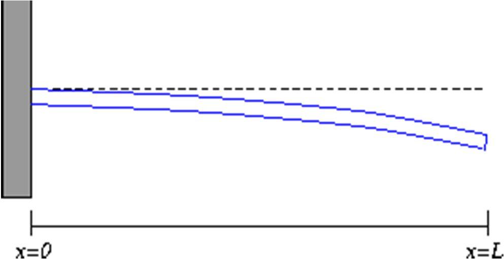
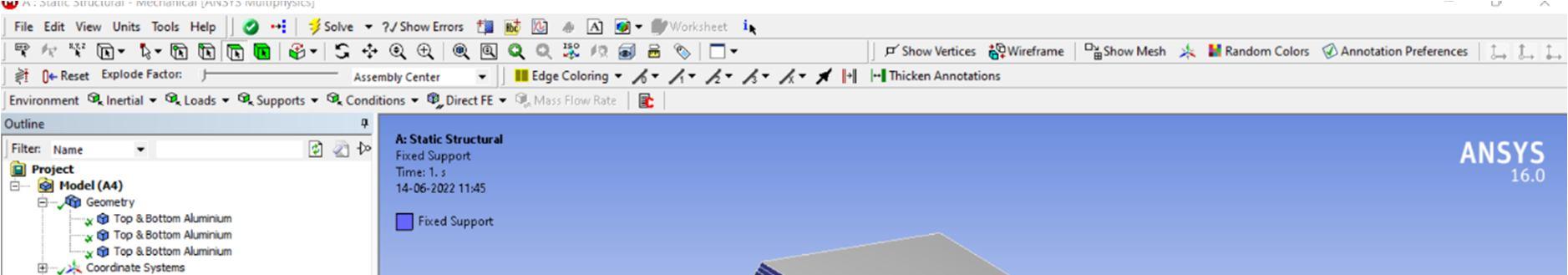
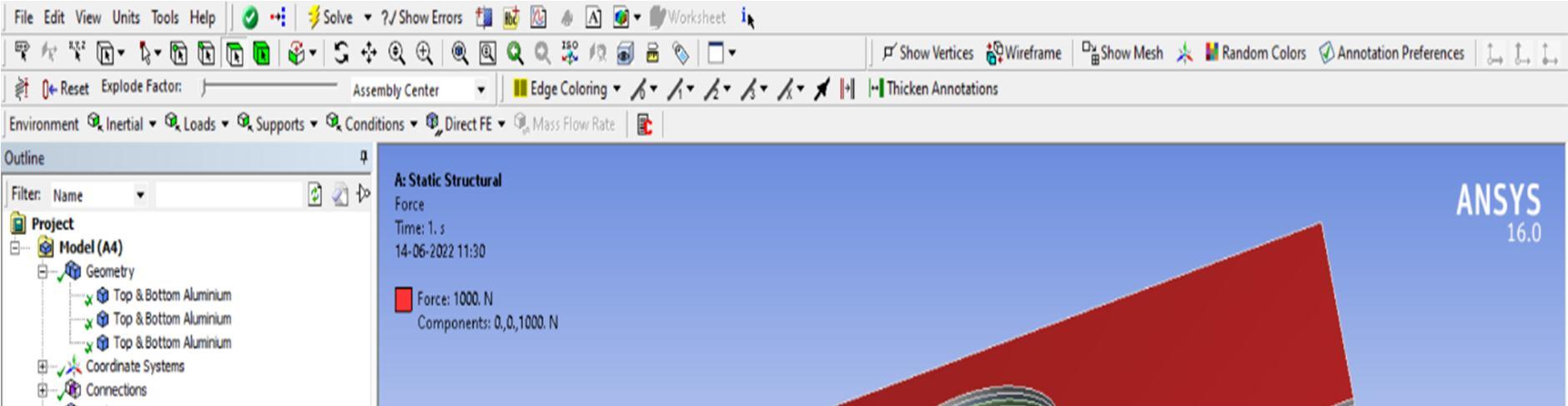
D. Boundary Conditions In that one end is fixed and the forces are applied on top of the laminated metal matrix composites.
Fig 1.6 One end is Fixed and Force is applied to the Bar
We know the value of aluminum Poisson’s ratio 67 73GPa in that value needs to apply in Ansys mechanical ADPL based on that value the properties will be derived.
International Journal for Research in Applied Science & Engineering Technology (IJRASET) ISSN: 2321 9653; IC Value: 45.98; SJ Impact Factor: 7.538 Volume 10 Issue VII July 2022 Available at www.ijraset.com 4549©IJRASET: All Rights are Reserved | SJ Impact Factor 7.538 | ISRA Journal Impact Factor 7.894 |
3) Static Structural >Model >Mesh >Generate Mesh
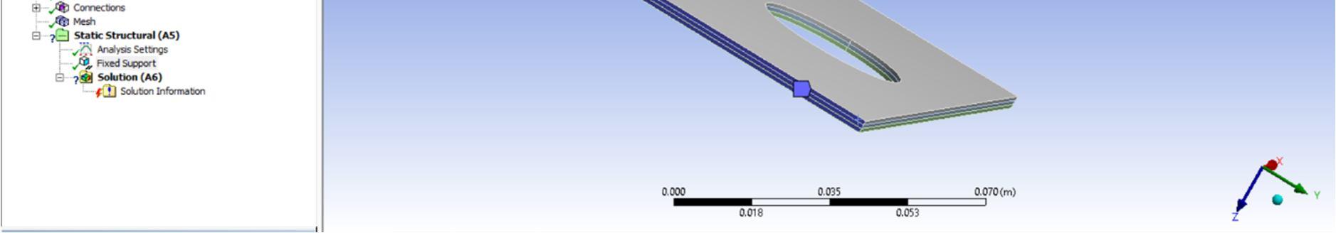
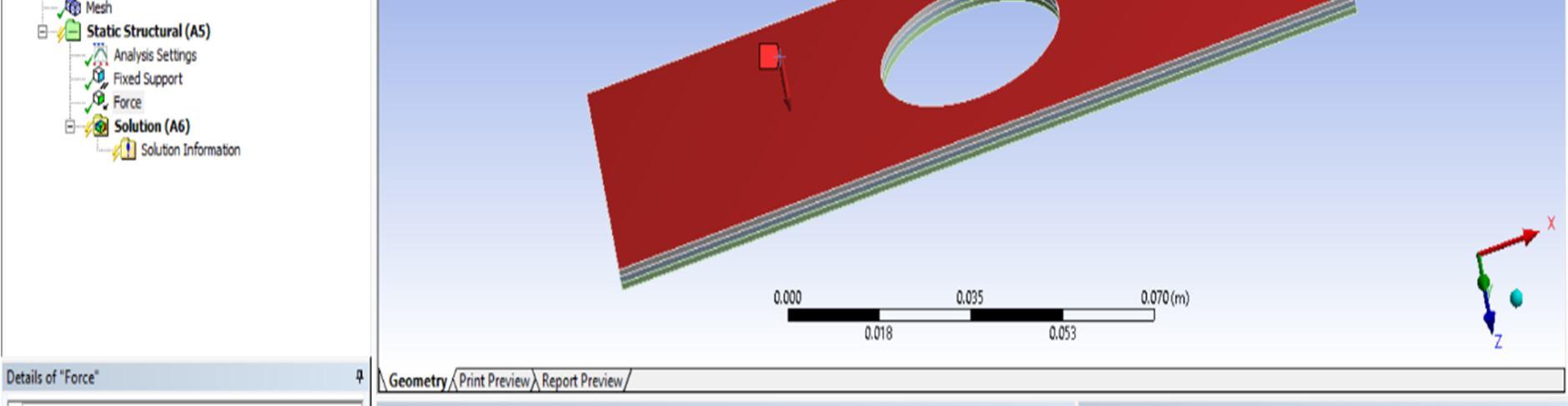
If you want fine mesh, go Sizing reduce that and make it. If you got a green tike then you go for fixed and force will be applied over the area. In that case, I applied 1000N over the area downside. After the applied load, if it’s correct shows a green tick. Then we go for what results want to compare the material properties.Fig1.8 Force applied in Ansys Fig 1.8 shows the force applied to that material’s downside
Similarly, the load was applied on the laminated metal matrix composite in Ansys. w(0)=0 This boundary condition says that the base of the beam (at the wall) does not experience any deflection. we(0)=0 Based on that boundary condition I’m given load to that Model. The blue is fixed support rest of the model is free in that another end needs forces. In Ansys after mesh select the static structural. A static structure having lots of options is their select fixed support. Based on the boundary conditions fix the one end I applied 1000N forces on over the area Below the diagram shows the fixed support. Fig 1.7 Fixed Support in Ansys After fixing the support we need to give load on over the area. Below the diagram shows that red is the load applied
International Journal for Research in Applied Science & Engineering Technology (IJRASET) ISSN: 2321 9653; IC Value: 45.98; SJ Impact Factor: 7.538 Volume 10 Issue VII July 2022 Available at www.ijraset.com 4550©IJRASET: All Rights are Reserved | SJ Impact Factor 7.538 | ISRA Journal Impact Factor 7.894 |
4) Static Structural >Model >Mesh >Generate Mesh >Static Structural (AS) > Fix the one end > Apply Force 1000N >Result >Solution >Equivalent Stress(von misses) >Total Deformation > solve If you apply the pressure, you can wrong value and deformation will occur. Above are the steps to follow to get the result from Ansys.
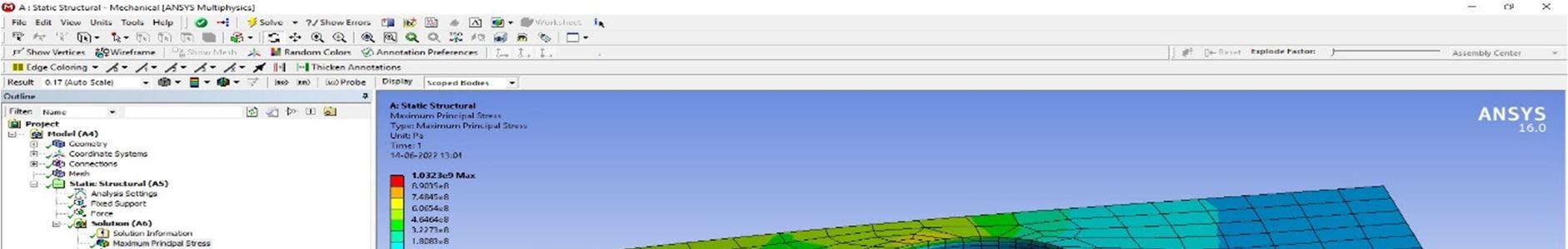
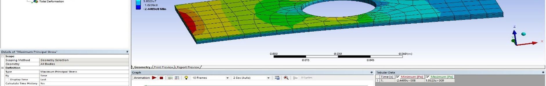
International Journal for Research in Applied Science & Engineering Technology (IJRASET) ISSN: 2321 9653; IC Value: 45.98; SJ Impact Factor: 7.538 Volume 10 Issue VII July 2022 Available at www.ijraset.com 4551©IJRASET: All Rights are Reserved | SJ Impact Factor 7.538 | ISRA Journal Impact Factor 7.894 | IV. RESULTS AND DISCUSSION A. Ansys Static Structural In Ansys based on the above boundary conditions, the forces are applied to their metal matrix composite based on that the result will come I checked two types with different combinations based on that the results will be varied. In the final going find which combination is an effective and good weight to strength ratio. Type 1) Top and bottom Carbon Fiber betweenFigAluminum1.9Equivalent stress (von misses) Maximum stress = 1.0323e9 Pa = 1032.23 MPa = 1.032 GPa Graph 2.1 Top and Bottom Carbon B/W Aluminum Equivalent stress B. Structural Deformation Fig 1.10 Total Deformation Maximum deformation = 0.031546 m = 31.54cm Factor of SafetyUltimate(FOS) stress Factor of SafetyAllowable= stress =1032.23MPa / allowable stress Allowable stress of aluminum = 1.03421e8 Pa = 103.421 MPa= 0.103421 GPa Allowable stress of Carbon Fiber = 137.895 MPa = 0.137.895 GPa 66.6 % percent of carbon and 33.3 % of Aluminum are used in that type of Combination so Allowable Stress Carbon 66% = 138/100 * 66.3 = 92 MPa Allowable Stress aluminum 33% = 103.4 /100*33.3=34.4 MPa Total allowable stress = 92+34.4=126.4 MPa Factor of Safety= 1032.23/126.4= 8.2
International Journal for Research in Applied Science & Engineering Technology (IJRASET) ISSN: 2321 9653; IC Value: 45.98; SJ Impact Factor: 7.538 Volume 10 Issue VII July 2022 Available at www.ijraset.com 4552©IJRASET: All Rights are Reserved | SJ Impact Factor 7.538 | ISRA Journal Impact Factor 7.894 | Above that material has a higher Factor of Safety. Based on allowable stress default values it is higher but in that laminated Metal Matrix Composite must be less than this. Need to test real time allowable stress. C. Equivalent Stress of Two Types of Laminated Plates Top and Bottom Carbon B/W Aluminum Top and Bottom Aluminum B/W Carbon Equivalent stress (Pa) Equivalent stress (Pa) Maximum 1.03E+09 Maximum 9.56E+08 8.90E+08 8.37E+08 7.48E+08 7.17E+08 6.07E+08 5.97E+08 4.65E+08 4.77E+08 3.23E+08 3.58E+08 1.81E+08 2.38E+08 3.89E+07 1.18E+08 1.03E+08 1.62E+06 Minimum 2.45E+08 Minimum 1.21E+08 Table 3.1 Equivalent Stress Two Types of Laminated Plates D. Comparisons Between Two Types of Laminated Plates Deformations Graph 2.4 Top and Bottom Carbon B/W Aluminum VS Top and Bottom Aluminum B/W Carbon Based on those results type one is better than type two laminates, so I’m going to manufacture top and bottom carbon between aluminum based laminated metal matrix composites. V. CONCLUSION Based on those results type one is better than type two laminates, so the top and bottom carbon between aluminum based laminated metal matrix composites are better effective and more weight to strength materials At the moment, composites are acknowledged as the material class with the best performance. In terms of technique and composition, the possibilities for making composite materials are essentially endless. They have been employed in all cutting edge technological disciplines in this context (aerospace, robotics, machine building). Finding a good weight to strength ratio is the main focus of the current investigation. Due to its exceptional specific strength property, metal matrix composites (MMCS) are becoming more and more popular as an alternative to conventional materials, particularly in the automotive, aerospace, and defense sectors. With carbon particles and an aluminum matrix acting as reinforcements, carbon MMC possesses several advantageous mechanical characteristics. A fabrication of MMCS has been attempted in the current investigation. 6050403020100 Top and Bottom Carbon B/W Aluminum Deformation Top and Bottom Aluminum B/W Carbon Deformation Deformation Comparisons Maximum Minimum
[7] M. A. Hoisington and J. C. Seferis, “Model Multilayer Structured Composites”,SAMPE Quarterly, [8] M. A. Hoisington,” Process/Property Interrelations of Layered Structured Composites”, Ph.D. Dissertation, Department of Chemical Engineering.
[10] J. W. Putnam, J. C. Seferis, T. Pelton and M. Wilhelm, “Perceptions of Prepreg Tackfor Manufacturability about Experimental Measures”, Science and Engineering of Composite Materials.
International Journal for Research in Applied Science & Engineering Technology (IJRASET) ISSN: 2321 9653; IC Value: 45.98; SJ Impact Factor: 7.538 Volume 10 Issue VII July 2022 Available at www.ijraset.com 4553©IJRASET: All Rights are Reserved | SJ Impact Factor 7.538 | ISRA Journal Impact Factor 7.894 | REFERENCES
[2] Chawla, K.K. Fibrous Materials, Cambridge University Press.
[3] Cyrot M., and D. Pavuna Introduction to Superconductivity and High Tc Materials, WorldScientific Publishers.
[5] J. D. Boyd, “Toughened Thermosetting Structural Materials”
[6] K. R. Hirschbuehler, “An Improved 270 0C Performance Interleaf System Having Extremely High Impact Resistance
[4] R. B. Gosnell, “Engineered Materials Handbook”, T. J., ed., ASM International.
[9] N.Odagiri, S. A. Suzue, H. Kishi, T. Nakae, A. Matsuzaki, “Highly Tough Composite Materials”
[1] M. A. Hoisington and J. C. Seferis, “Process Structure Property Relationships for layered Structured Composites”, Proc. 6th Tech. Conf. Am. Soc. For Composites.