https://doi.org/10.22214/ijraset.2023.48937

11 I January 2023
ISSN: 2321-9653; IC Value: 45.98; SJ Impact Factor: 7.538

Volume 11 Issue I Jan 2023- Available at www.ijraset.com

https://doi.org/10.22214/ijraset.2023.48937
ISSN: 2321-9653; IC Value: 45.98; SJ Impact Factor: 7.538
Volume 11 Issue I Jan 2023- Available at www.ijraset.com
1M.Tech Student, 2Professer, Department of Civil Engineering, Ujjain Engineering College, Ujjain(M.P.),India
Abstract: Although there are numerous various kinds of bridge structures in the world, the skew culvert bridge is the subject of this essay. Skew bridges are unique in that they are frequently seen in hilly terrain and are also used in contemporary architecture. Skew slab bridges are an attempt to analyze in this dissertation. In order to achieve maximal stresses development on the slab, various I.R.C. loadings (Class 70R Tracked Vehicle) and live load positions have been taken into consideration in the analysis. For the skew bridge analysis, the thorough analysis and parametric investigation offered insightful information. The primary strategy is to examine the impact of various depths on the maximum shear force, bending moment, stresses, and reinforcing quantity, among other parameters, on the 170, 300and 570 skew angle respectively.
Keywords: Skew angle, stresses, IRC loading and skew slab etc.
The roof and floors of structures with a reinforced concrete structure are made of slabs. Skew slabs, which are four-sided slabs with equal opposing angles other than 900, deviate from the standard rule that slabs should be perpendicular to the supports. In the event of obstructions, this slab form offers an engineer a wide range of alignment opportunities. The short diagonal to span ratio controls how a simply supported skew slab responds to a central point load. Acute corner lifting is present in skew slabs with a short diagonal to span ratio less than one, but not in those with a short diagonal to span ratio more than one. Any bridge whose longitudinal axis makes a sharp angle with the abutment is said to be skew. Such a structure's design is a result of terrain features like mountainous topography, intricate intersections, and natural barriers. Skew bridge design requires particular consideration because the nature of skew bridges differs significantly from that of conventional bridges. Normal bridges have a deck slab that is perpendicular to the supports, which allows the load to be transferred from the slab to the supports, which are positioned perpendicular to the slab.On the other hand, load transference from a skew slab bridge is a challenging issue because it is never certain which way the slab will span and how the load will be transferred to the support.

The angle between the free (longitudinal) edge and perpendicular to the abutment is referred to as the skew . In comparison to a right-angled bridge, the existence of skew makes bridge analysis and design much more challenging. It also significantly affects the structural behaviour of decks and the key design stresses. In simple supported bridges, the effect of skew may typically be ignored up to 15° of skew, and the bridge can be constructed as a right angled bridge. However, with integrated bridges and continuous decks, the effects of skew become noticeable at smaller skew angles, especially in areas of intermediate supports. Although the need for building skew bridges was recognised on a global scale in the early 1960s, it is clear from the literature review that the study work has only focused on specific issues encountered in the fields.

ISSN: 2321-9653; IC Value: 45.98; SJ Impact Factor: 7.538
Volume 11 Issue I Jan 2023- Available at www.ijraset.com
There are currently 4 types of IRC loading according to IRC: 6 - 2014 which are considered as live load for the bridge design.
This loading has been recently introduced in IRC:6 - 2014. It includes tracked loading as well as wheeled loading. We can say that this is an improved version of the IRC class AA loading (IRC:6 - 2000). This loading has the highest magnitude with respect to all other IRC loadings. This loading is commonly used for building bridges in the industrial sector and the military sector. Maximum load of one wheel in case IRC Class 70R loading is 350Kn. This is different from the IRC class AA loading in the longitudinal length of the load which is 4.57m.
This loading as described by IRC: 6-2000 for bridge design based on 2000. This was before loading IRC Class 70R has highest quantity of loading magnitude. This loading before starting IRC Class 70R was considered for the design of bridges for the military sector, industrial area and Highway loading. As IRC Class 70R IRC loading in the same way the Class AA loading also had a maximum load of 350KN for single wheel and as longitudinal load length 3.6m.
These two loadings are considered as lighter loading than the IRC class 70R and IRC Class AA loading. These loadings are considered for the bridge design of rural area or we can say for wooden bridges. Max load of single wheel loading for IRC Class A is 114Kn and for IRC Class B loading is 68Kn.
When a stream crosses the road at an angle other than 90 degrees, skew bridges are required. The current traffic scenario necessitates straight road alignment due to the quick traffic, which in turn necessitates the use of skew crossings. Bridges are parallelograms when they are in their plane form, and the angle that results when you remove the acute angle from 90 degrees is known as the skew angle.
The solid RCC slab with a clear span of 7.5 metres is taken into consideration in this study. Various codes, including IS 456-2000 for RCC design and IRC 6 2000 for live load, are applied in the current study. The study focuses on manually calculating the impact of various skew angles on slab culverts. Different skew angles of the slab culvert are calculated, and the results are compared in terms of their moment, shear, stresses, and area of steel. In our analysis, we take into account the live and dead loads in accordance with Indian standard code standards.
ISSN: 2321-9653; IC Value: 45.98; SJ Impact Factor: 7.538
Volume 11 Issue I Jan 2023- Available at www.ijraset.com
Here in this research we have considered varying depth of the slab at different skew angle ( 170, 300 and 570) and analyze the results in terms of shear force, shear stress, Area of steel and moment etc.
The limit state design method described in Provides-codes 800:2007 and 456:2000 is the foundation for the analysis. For the live load in this investigation, we also use the IRC6:2000 code. In this study section, several skew angles have been used to examine the effects on shear, moment, and the amount of steel in the culvert slab. The analysis method is manual and follows IS standards. The outcomes that are listed below have been discussed -

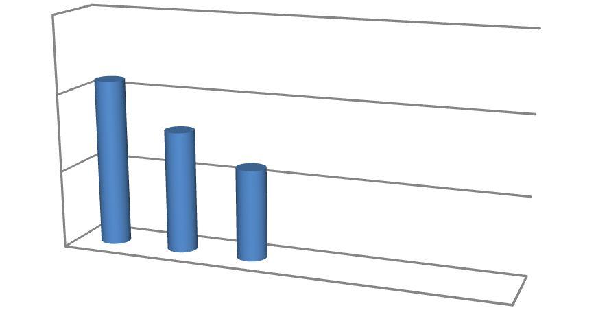
Here the comparison of moment due to dead load for different thickness of the slab culvert at an
respectively. The results and graph are shown below-
1) For Skew Angle 170 -
angle

ISSN: 2321-9653; IC Value: 45.98; SJ Impact Factor: 7.538
Volume 11 Issue I Jan 2023- Available at www.ijraset.com
In the above results and graph it is notice that the moment due to Dead load is increasing as we increasing the depth of slab at an angle of 170, 300 and 570 respectively of the skew culvert


ISSN: 2321-9653; IC Value: 45.98; SJ Impact Factor: 7.538
Volume 11 Issue I Jan 2023- Available at www.ijraset.com
Here the comparison of moment due to Live loadfor different thickness of the slab culvert at an skew angle of
respectively. The results and graph are shown below-


1) For skew angle 170 -
Table
Depth in mm Moment due to live load in
2) For skew angle 300 –

ISSN: 2321-9653; IC Value: 45.98; SJ Impact Factor: 7.538
Volume 11 Issue I Jan 2023- Available at www.ijraset.com
In the above table it is notice that the moment due to Live load is decreasing as we increasing the depth of slab at an angle of 17
, 300 and 570 respectively of the skew culvert.
Here the comparison of shear stress for different thickness of the slab culvert at an skew angle of 170, 300 and 570 respectively. The results and graph are shown below-
0 -
ISSN: 2321-9653; IC Value: 45.98; SJ Impact Factor: 7.538
Volume 11 Issue I Jan 2023- Available at www.ijraset.com
In the above table it is notice that the shear stress is decreasing as we increasing the depth of slab at an angle of 17
respectively of the skew culvert.
,
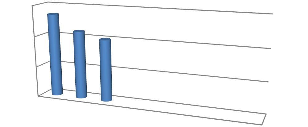
Here the comparison of shear force for different thickness of the slab culvert at an skew angle of 17
and 57
respectively. The results and graph are shown below-


ISSN: 2321-9653; IC Value: 45.98; SJ Impact Factor: 7.538


Volume 11 Issue I Jan 2023- Available at www.ijraset.com
ISSN: 2321-9653; IC Value: 45.98; SJ Impact Factor: 7.538
Volume 11 Issue I Jan 2023- Available at www.ijraset.com
3) For skew angle 570
It can be clearly seen from the above table and graph the shear force is increasing on increasing the depth of slab at an angle of 170 , 300 and 570 respectively of the skew culvert.
In the analysis of slab culvert structure the effect of different thickness of slab culvert structure are shown clearly. Now come to the conclusion points, the conclusion are drawn from comparison the results of shear force, moment due to dead load,moment due to live load, Shear force and shear stress are shown below. Following conclusions are made from this study work.
1) The analysis shows that the moment due to dead load is increases as we increases the depth of the slab from 600 mm to 1000 mm depth of the culvert at an skew angle of 170 , 300 and 570 respectively.
2) It is about 70% , 71% and 82% increase in the magnitude of the moment due to dead loadfrom 600 mm to 1000 mm depth of the culvert slab at an skew angle of 170, 300 and 570 respectively
3) The analysis shows that the moment due to live load is decreases as we increases the depth of the slab from 600 mm to 1000 mm depth of the culvert at an skew angle of 170 , 300 and 570 respectively.
4) It is about 45% , 46% and 47% decrease in the magnitude of the moment due to live load from 600 mm to 1000 mm depth of the culvertslab at an skew angle of 170, 300 and 570 respectively
5) The analysis shows that the shear stress is decreases as we due increases the depth of the slab from 600 mm to 1000 mm depth of the culvert at an skew angle of 170 , 300 and 570 respectively
6) It is about 26% , 25% and 26% decrease in the magnitude of the shear stress from 600 mm to 1000 mm depth of the culvertslab at an skew angle of 170, 300 and 570 respectively

7) The analysis shows that the shear force is increases as we increases the depth of the slab from 600 mm to 1000 mm depth of the culvert at an skew angle of 170 , 300 and 570 respectively.
8) It is about 29% , 25% and 24% decrease in the magnitude of the shear force from 600 mm to 1000 mm depth of the culvertslab at an skew angle of 170, 300 and 570 respectively
[1] B.Patra (February 2013) Analysis Of Skew Slab Deck Using Analytical Methods.
[2] kolaventirajkumar ( Published date: 18/09/2017) Design and Study on Behaviour of Skew Slab Bridges with Various Skew
[3] Ghaidak A. Fadhil (14 December 2008) Effects Of Skewangle On Bending Moment's Distribution In The Skewbridge Deck
ISSN: 2321-9653; IC Value: 45.98; SJ Impact Factor: 7.538
Volume 11 Issue I Jan 2023- Available at www.ijraset.com
[4] HimanshuGuleria (Volume: 06 Issue: 12 | Dec 2019) Review On Skew Slab Bridges.
[5] Ibrahim SaleemHarba (August 2011) Effect Of Skew Angle On Behavior Of Simply Supported R. C. T-Beam Bridge Decks.
[6] Md. Khasro Miah1 and AhsanulKabir (06 December 2005) A study on reinforced concrete skew slab behavior.
[7] S.K 1, Krishnachandran V.N. (Aug-2016) Effect of Reinforcement Pattern on the Behaviour of Skew Slab
[8] Ibrahim S. I. Harba (AUGUST 2011) EFFECT OF SKEW ANGLE ON BEHAVIOR OF SIMPLY SUPPORTED R. C. T-BEAM BRIDGE DECKS
[9] Alok Singh1, Abhishek Kumar2, Mohd. Afaque Khan3 (Volume: 03 Issue: 03 | Mar-2016) Effect of Skew Angle on Static Behavior OfReinforced Concrete SlabBridge Decks.
[10] Sindhu B.V1, Ashwin K.N2, Dattatreya J.K.3, S.V Dinesh4 (Nov-2013) EFFECT OF SKEW ANGLE ON STATIC BEHAVIOUR OF REINFORCEDCONCRETE SLAB BRIDGE DECKS
[11] Deepak C1, Sabeena MV2 (May-2015) EFFECT OF SKEW ANGLE ON UPLIFT AND DEFLECTION OF RCCSKEW SLAB
[12] Santhosh Kumar R1, Dr. MahadevAchar M2, Dr. H Eramma3 (Jan 2019) Effect of Skew Angle on the Behavior of Bowstring Girder Bridge
[13] P.M. Kulkarni1, P.M. Mohite2 (Aug 2019) Parametric Study on Behaviour of Rectangular Box Girder Bridges withVarying Skew Angle.
[14] Nasir1, Himanshu Guleria2 (Dec 2019) REVIEW ON SKEW SLAB BRIDGES
[15] Prashant Kumar Tripathi1 and Rajendra Kumar Srivastava2 ( June 2019) EFFECT OF SKEW ANGLES ON A SKEW SLAB BOX CULVERT