10 XII December 2022 https://doi.org/10.22214/ijraset.2022.47991
ISSN: 2321-9653; IC Value: 45.98; SJ Impact Factor: 7.538 Volume 10 Issue XII Dec 2022- Available at www.ijraset.com

ISSN: 2321-9653; IC Value: 45.98; SJ Impact Factor: 7.538 Volume 10 Issue XII Dec 2022- Available at www.ijraset.com
Ramakrishnaiah1 , Dr. H.N. Vidyasagar2 , Dr. H.K. Shivanand3
1Assistant professor, Dayananda Sagar Academy of Technology and Management, Bangalore 2Professor, University Visveswaraya College of Engineering, Bangalore, India 3Professor, University Visveswaraya College of Engineering, Bangalore, India

Abstract: The metal matrix composites are the wide family of materials aimed to enhancing of combined properties of reinforcements.
The matrix utilized in the development of MMCs would be of any material, but preferably aiming for lighter structural materials and main objective is in the improvement of mechanical properties. Majority of the progress in the field of MMCs is closely connected to development in reinforcement for incorporation in MMCs. But the orientation of this research is towards the fabrication and testing of Al8011, Silicon Carbide and S-glass fibre are the combination to cast the hybrid MMCs. The metallic matrix used in the present investigation is Aluminium alloy.
Metal matrix composites (MMCs) possess significantly improved properties including high specific strength; specific modulus, damping capacity and good wear resistance compared to unreinforced alloys. There has been an increasing interest in composites containing low density and low-cost reinforcements.
The present investigation has been focused on the using of silicon carbide and S-glass fibre as a reinforcement material in useful manner by dispersing in variable quantity into Aluminium-8011 to produce Hybrid MMCs by stir casting method and there by investigating its mechanical properties such as compressive strength and hardness of Al8011 metal matrix hybrid composites. Hence, it is proposed to form a new class of composite. Al8011 alloy reinforced with Silicon Carbide and S-glass to form MMCs using graphite crucible for casting. The MMC is obtained for different composition of SiC and S-glass fibre.
Keywords: Metal matrix composites, stir casting, Sic, S-glass fibre
Conventional monolithic materials have limitations in achieving sensible combination of strength, stiffness, toughness and density. to beat these shortcomings and to satisfy the ever-increasing demand of contemporary technology, composites area unit most promising materials of recent interest.
Metal matrix composites (MMCs) possess considerably improved properties together with high specific strength; specific modulus, damping capability and sensible wear resistance compared to unreinforced alloys. There has been associate degree increasing interest in composites containing density and affordable reinforcements.

Among varied discontinuous dispersions used, s-glass fibre and semiconductor fibre as reinforcement area unit possible to beat the value barrier for wide unfold applications in automotive and tiny engine applications. it's so expected that the incorporation of sglass fibre and carbide particles in aluminium alloy.
Now each day the particulate strengthened aluminium matrix composite area unit gaining importance as a result of their low price with benefits like identical properties and therefore the risk of secondary process facilitating fabrication of secondary parts. forged aluminium matrix particle strengthened composites have higher specific strength, specific modulus and sensible wear resistance as compared to unreinforced alloys. whereas work the chance of mistreatment carbide and s-glass fibre as reinforcing component within the aluminium soften. The particulate composite are often ready by injecting the reinforcing particles into liquid matrix through liquid scientific discipline route by casting. Casting route is most well-liked because it is a smaller amount pricey and amenable to production.
Engineering Technology (IJRASET)
ISSN: 2321-9653; IC Value: 45.98; SJ Impact Factor: 7.538 Volume 10 Issue XII Dec 2022- Available at www.ijraset.com
1T R Mohan, C M Sharanaprabhu and Shashidhar K Kudari (2015) “Study on the results of set on Particles on Tensile Properties for Al/Sic Composites”, International Journal of Science, Technology and Management, Vol 04, Special Issue No. 01, March 2015, pp 1477-1483.
The conventional low value stir casting technique was with success adopted within the preparation of Al/SiC composite. Since, the microstructural studies discovered the uniform distribution of the particles within the matrix system, the set on particle additions to Al matrix can will increase the modulus of snap and yield strength of the composite. however the elongation decreases with the rise within the volume fraction of the set on particles to Al metal matrix composite. The tensile properties and microstructure analyses were dole out for varied weight proportions of set on particles. The observations of distributed set on particles before and once tensile take a look at specimens were dole out mistreatment Scanning microscope.
2Mr. A. R. Dhatrak and Dr. K. B. Kale. (2016) “Wear Rate Investigation of Al primarily based carbide Metal Matrix Composite Embedded with Copper”, IJIRST –International Journal for Innovative analysis in Science & Technology, Volume 3, Issue 04, September 2016. Pp 376-384. The wear and volume loss increase with increase in traditional load, slippery speed and temperature. the wear and tear ascertained is lowest for the composite containing copper as compared to the composite Al+25%SiC. this can be thanks to formation of tribular at the sexual practice interface that reduces the wear and tear. This report cares with Al Matrix Composites and additional specifically on the Al (Al) primarily based carbide (SiC) metal matrix composite Embedded with Copper. the most aim of this project is to examine usefulness of the Al primarily based carbide metal matrix composite for rider vehicle lining. Through this thesis an endeavour is created to check the tribological behaviour of the Al primarily based carbide metal matrix composite.
3M. Asif, K. Chandra and P.S. Misra “Development of Al primarily based Hybrid Metal Matrix Composites for serious Duty Applications” Journal of Minerals & Materials Characterization & Engineering, 2011. Vol. 10, No.14, pp.1337-1344. Incorporation of plumbago particles within the Al matrix as a second reinforcement. Decreases the wear and tear rates of the composite compared to set on bolstered composite. constant of friction is stabilised with incorporation of solid lubricants in composition of composite at solid state for varied slippery speeds and applied hundreds. Incorporating solid ingredients in Al powder play a crucial role to cut back the background level. The results reveal that wear rate of hybrid composite is not up to that of binary composite. the wear and tear rate attenuated with the increasing load and accumulated with increasing speed.
4Frederick T. Wallenberger, James C. Watson, and Hong Li (2001) Glass Fibres, ASM International. All Rights Reserved. ASM vade mecum, Vol. 21, PPG Industries, Inc.
All glass fibres represented during this article area unit derived from compositions containing silicon dioxide. They exhibit helpful bulk properties like hardness, transparency, resistance to chemical attack, stability, and immobility, also as fascinating fiber properties like strength, flexibility, and stiffness. Glass fibres area unit employed in the manufacture of structural composites, computer circuit boards and a large vary of special-purpose merchandise. Glass fibres area unit created by direct draw method and shaped by extruding liquid glass through a noble metal alloy bushing which will contain up to many thousand individual orifices, every being zero.793 to 3.175 mm (0.0312 to 0.125 in.) in diameter. The enduringness of glass fibres is decided by the structure property of the salt network, notably, by the absence of alkali oxides, that don't seem to be promptly integrated into the structure. The structure of B chemical compound, though' being a neighbourhood of the network, is weaker than that of silica, and thus, B chemical compound is a flux. many high strength glass fibres area unit notable, as well as S-glass’s-glass and S-2 glass fibres, a product variant, have constant glass composition however completely different coatings. whereas internal structural uniformity (high strength) is achieved with these boron-free and alkali-free compositions, their forming temperatures area unit more than that of E-glass.
5A. Elanthiraiyan*, G. Antonius Casmir Jayaseelan, S. Ashok Kumar And S. Sathiyaraj (2016), “Investigation of Machining Characteristics of Al 8011 By Wire Cut EDM Process”, Department of applied science, Aarupdai Veedu Institute of Technology, Vinayaka Missions University, Chennai (T.N.) India. Vol 4, pp 3119-3130. In this study, the influence of brass wire on the performance of WEDM is compared with metallic element wire. And, the result of method parameters on the method performance determined by playacting experiments underneath completely different machining conditions. Experiments results of WEDM of atomic number 74 inorganic compound indicate peak current and pulse on have vital result on MRR and surface roughness. The machining characteristics of wire-cut EDM method in Al alloy 8011, the instrumentality used for machining is EZEECUT and Wire cut EDM. Brass wires area unit used as conductor within the combination of 2 nonferrous metals, alloyed in between the vary 63%–65% copper and 35%–37% metal. The nonconductor for experiments was Deionized water. The results obtained from the experiments were analyzed mistreatment ANOVA and also the factors have an
ISSN: 2321-9653; IC Value: 45.98; SJ Impact Factor: 7.538 Volume 10 Issue XII Dec 2022- Available at www.ijraset.com
effect on MRR and surface end were found. mistreatment Taguchi’s technique, we've known the optimum method parameters for machining Al 8011.
6Neelima Devi. C, Mahesh.V and Selvaraj. N (2011), “Mechanical characterization of Al carbide composite”, International Journal of Applied Engineering analysis, Dindigul Volume one, No 4, 2011, pp 1642-1649. Conventional materials like Steel, Brass, Al etc. can fail with none indication. Cracks initiation, propagation can takes place inside a brief span. during this paper durability experiments are conducted by variable mass fraction of assail (5%, 10%, 15%, and 20%) with Al. the utmost durability has been obtained at V-day assail magnitude relation. Mechanical and Corrosion behaviour of Al carbide alloys also are studied. variety 13|metallic element| metal} carbide alloy composite materials area unit wide used for a several number of applications like engineering structures, region and marine application. the burden to strength magnitude relation for Al carbide is regarding thrice that of steel throughout tensile check. Al carbide alloy stuff is 2 times less in weight than the Al of an equivalent dimensions. the utmost durability has been obtained at V-day assail magnitude relation.
7A. O. Inegbenebor, C. A. Bolu, P. O. Babalola, A. I. Inegbenebor, O. S. I. Fayomi.” atomic number 13 carbide Particulate Metal Matrix Composite Development Via Stir Casting Processing” Springer Science Business Media Dordrecht 2016, one August 2016, pp 9451-9458.
In this paper, typical easy ways of manufacturing MMC with earned properties through the dispersion of carbide within the matrix area unit investigated. to attain these objectives a ballroom dance mix methodology of stir casting technique was utilized. Experiments were conducted by variable the burden fraction of assail for two.5 %, 5.0 %, 7.5 try to ten nada. The metal matrix composite (MMC) materials created show that modulus and hardness had higher values than the unreinforced base metal atomic number 13. The stir casting methodology gave the impression to disperse little grit of carbide within the matrix higher than the larger grit, that resulted within the improvement of the strength and mechanical properties of the composite alloy. the little grit size of carbide influences the strength of mechanical properties of the composites. The purpose of this literature review is to gift the key results of a number of the foremost relevant analysis within the space of composite materials. The sustained interest to develop engineering materials that might deal with the raised performance standards, resulted in emergence of a more modern category of materials, referred to as Metal Matrix Composites (MMCs). They represent a family of customizable materials with customizable critical-property relationships. Such materials area unit best-known for his or her exceptional high modulus, stiffness, wear resistance, fatigue life, strength-to-weight ratios, tailorable constant of thermal enlargement, etc. With these enhancements in properties, they create for robust electioneering for exchange typical structural materials. however, what makes them stand apart is that the ability to customise their properties to suit the service demand. Such blessings have created this cluster of materials a pleasant decide to be used in weight-sensitive and stiffness-critical elements in transportation systems.
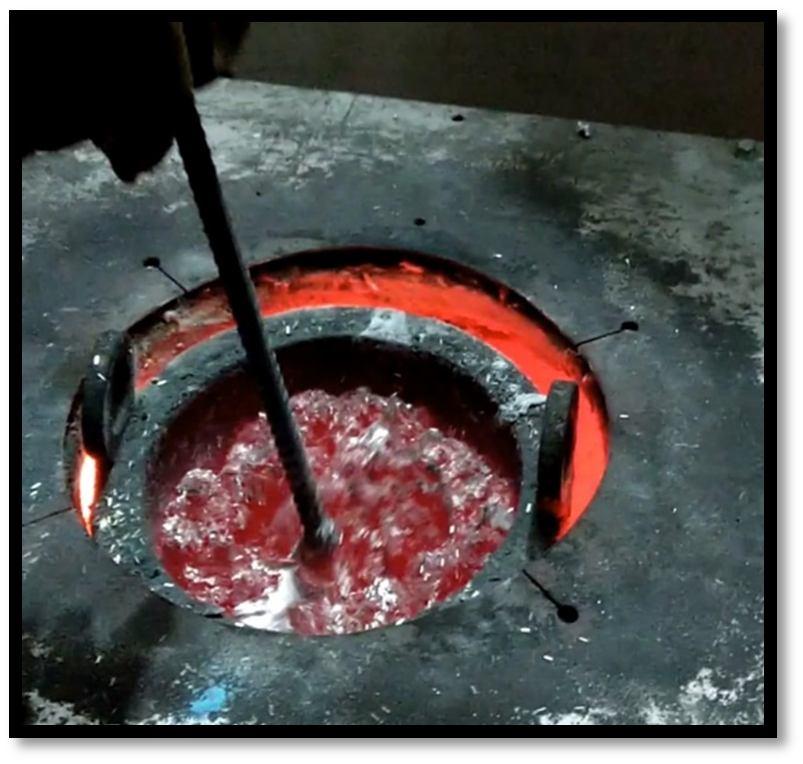
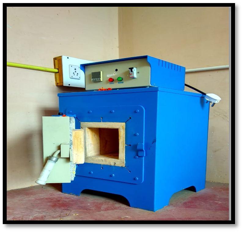
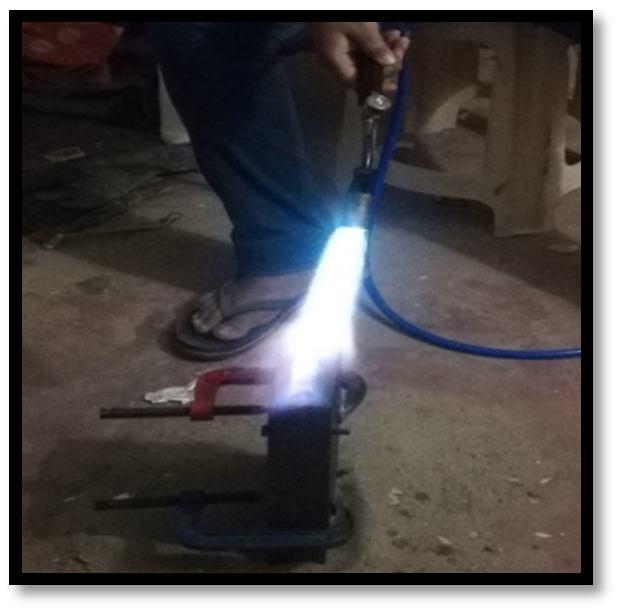
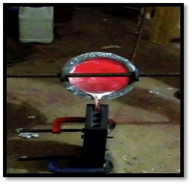
The following are the representation of stir casting process to produce hybrid aluminium metal matrix composites. The crucible furnace used in this process is shown in the following figure 1.1 and 1.2.
ISSN: 2321-9653; IC Value: 45.98; SJ Impact Factor: 7.538 Volume 10 Issue XII Dec 2022- Available at www.ijraset.com
The pouring of molten metal into the die cavity is shown in the figure 1.3(a)&(b) shows the preheating of mould and (c) shows the casted aluminium products are opened from the die and they are ready for machining as per ASTM standards.
(a) (b) (c) Fig.1.3 (a) Pouring of molten mixture into die, Fig.(b) Preheating of moulded die. Fig.(c) Casted aluminium Specimens
First of all, 1100 gm of commercially available aluminium 8011 was melted in a resistance heated muffle furnace and casted in a clay graphite crucible. For this the melt temperature was raised to 750oC.
Silicon Carbide and S-glass fibers are mixed in the red-hot liquid Al 8011 kept in the crucible in the required composition. By stir casting method all the composites are well stirred such all the constituent material get mixed properly with the base metal that is Al8011.
Three-phase electrical resistance type 10KW capacity furnace, the temperature range of the furnace is 1000° C with a controlled accuracy of ±10°C fitted with digital temperature controller. The shooting capacity of the furnace is 500° C per hour
Muffle furnace was used to preheat the particulate to a temperature of 500° C. It was maintained at the temperature till it was introduced in to the Al 8011 alloy melt. The preheating of reinforcement isnecessary in order to reduce the temperature gradient and to improve wetting between the molten metal and the particulate reinforcement.
The melting range of Al 8011 alloy is of 700-800°C. A known quantity of Al 8011 ingot wear pickled in 10% NaOH solution at room temperature for 10 min. pickling was done at remove the surface impurities. The smut formed was removed by immersing the ingots for 1 min mixture of one-part nitric acid and one-part water followed washing in methanol. the cleaned ingot after drying in air were loaded into the graphite crucible of the furnace for melting. The melt was super-heated to a temperature of 800°C and maintained at that temperature. The molten metal was then degassed using Hexa-Chloro ethane tablets for about 8 min.
Alumina coated stainless steel impeller was used to stir the molten metal to create a vertex. The impeller was of centrifugal type with three blades welded at 45° inclinations and 120° apart. The stirrer was rotated at a speed 300-400 rpm and a vertex was created in the melt. The depth of immersion of impeller was approximately one third of the height of the molten metal. From the bottom of the crucible. The pre- heated particulates of Silicon Carbide and short S-Glass fibre were introduced into the vertex at the rate of 120 gm/min.
ISSN: 2321-9653; IC Value: 45.98; SJ Impact Factor: 7.538 Volume 10 Issue XII Dec 2022- Available at www.ijraset.com
No. of Casting Al 8011(%) S-Glass fiber (%)
Silicon Carbide (%) Sample No.
Casting 1 100 0 0 A00
Casting 2 97 0 3 A03
Casting 3 95 0 5 A05
Casting 4 93 0 7 A07
Casting 5 98 2 0 A20
Casting 6 95 2 3 A23
Casting 7 93 2 5 A25
Casting 8 91 2 7 A27
Casting 9 96 4 0 A40
Casting 10 93 4 3 A43 Casting 11 91 4 5 A45
Casting 12 89 4 7 A47
Casting 13 94 6 0 A60
Casting 14 91 6 3 A63 Casting 15 89 6 5 A65 Casting 16 87 6 7 A67
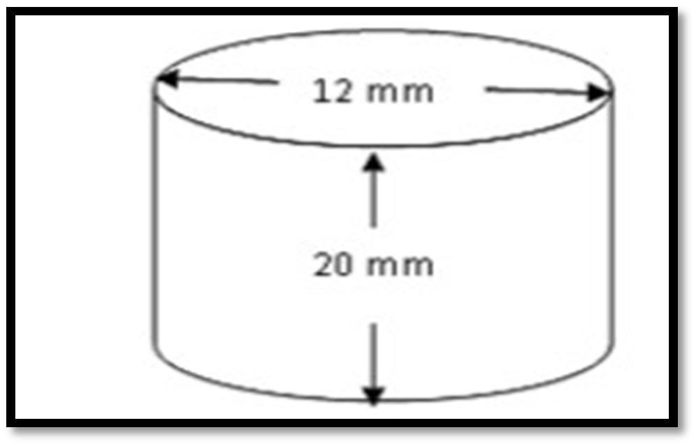
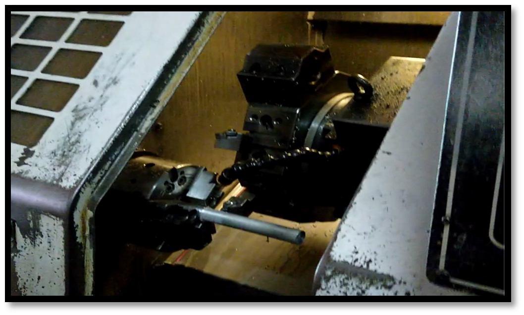
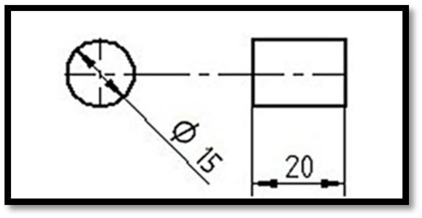
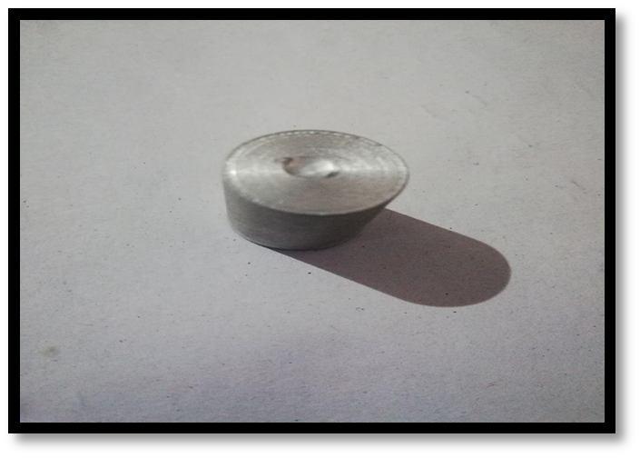
The compression specimen used for this project was machined according to ASTM E9 standards using CNC turning machine. The dimension to which the work piece was machined and the process of machining is shown in the figure 1.4 and 1.5 respectively.
Fig.1.4 Machining of compression specimen
A. Machined Samples of Compression Test Specimens
Fig.1.5 Compression test specimen (ASTM E9 standards)
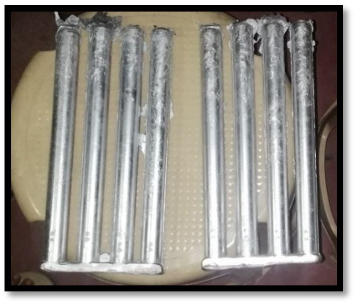
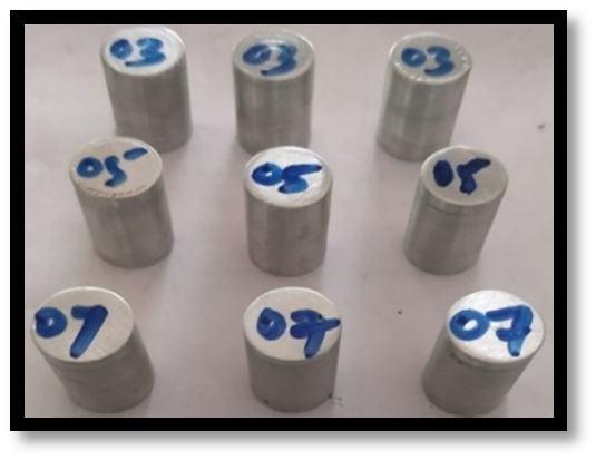
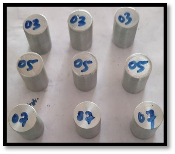
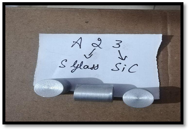
The machined samples for compression tests are shown below. All the specimens are machines as per ASTM E9 standard. The first samples are the combination of 0% S-glass fibre reinforced with 3%, 5%, 7% Sic.
ISSN: 2321-9653; IC Value: 45.98; SJ Impact Factor: 7.538 Volume 10 Issue XII Dec 2022- Available at www.ijraset.com
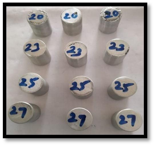
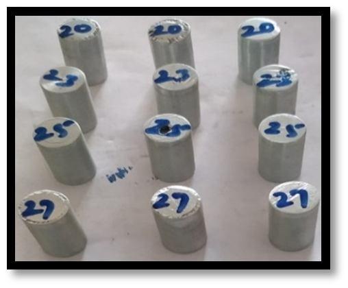
The second combination of samples are obtained for the combination of 2% S-glass fibre reinforced with 0%, 3%, 5%, 7% Sic
(a) (b) (c) (d)
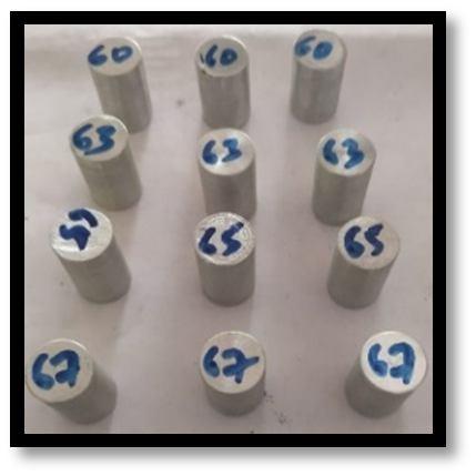
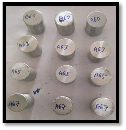
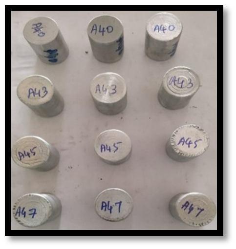
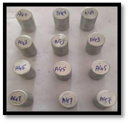
Fig.1.6 (a) A03, A05, A07, (b) A20, A23, A25, A27, (c) A40, A43, A45, A47, (d) A60, A63, A65, A67 Compression Test Specimens
The third combination of samples are obtained for the combination of 4% S-glass fibre reinforced with 0%, 3%, 5%, 7% Sic The fourth combination of samples are obtained for the combination of 6% S-glass fibre reinforced with 0%, 3%, 5%, 7% Sic
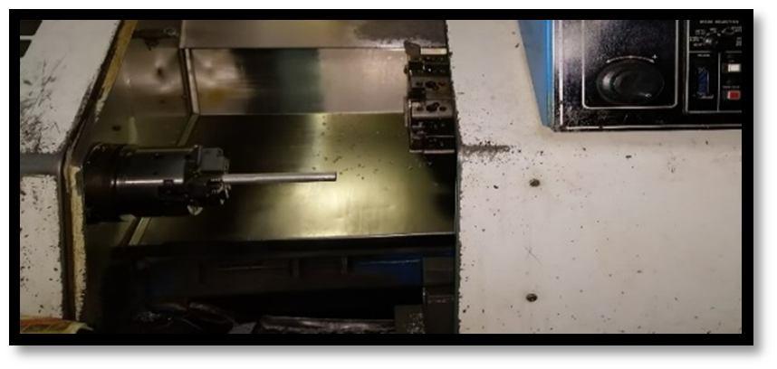
The hardness specimen used for this project was machined according to ASTM E10 standards using CNC turning machine. The dimension to which the work piece was machined and the process of machining is shown in the figure 1.7 and figure 1.8.
Fig.1.7. Brinell hardness test specimen (ASTM E10 standards) Fig.1.8. Machining of hardness test specimen
The hardness specimen used for this project was machined according to ASTM E10 standards using CNC turning machine. The dimension to which the work piece was machined and the process of machining is shown in the figure 1.7 and figure 1.8
The casted specimens are machined to conduct hardness test. The following test specimens are prepared for various weight percentage of test specimens according to ASTM E10 standard.
The second combination of samples are obtained for the combination of 2% S-glass fibre reinforced with 0%, 3%, 5%, 7% Sic The third combination of samples are obtained for the combination of 4% S-glass fibre reinforced with 0%, 3%, 5%, 7% Sic The fourth combination of samples are obtained for the combination of 6% S-glass fibre reinforced with 0%, 3%, 5%, 7% Sic
Fig.1.9. A03, A05, A07, A20, A23, A25, A27, A40, A43, A45, A47, A60, Fig.2.5A63, A65, A67 Hardness Test Specimens
ISSN: 2321-9653; IC Value: 45.98; SJ Impact Factor: 7.538 Volume 10 Issue XII Dec 2022- Available at www.ijraset.com
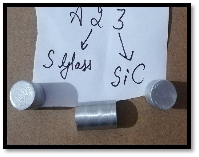
Compression test was conducted on the specimen using a Universal Testing Machine. The various procedures involved are: The original dimensions of the specimen like original dia., gauge length etc. is to be measured. The specimen is mounted on the Universal Testing machine between the fixed and movable jaws. The load range in the machine is adjusted to its maximum capacity (300 tonnes) the dial gauge is mounted on the machine at the appropriate positions and adjusted to zero. The machine is switched on and the compressive load is applied gradually. The specimen is loaded continuously up to the ultimate load (red needle will stop) which is to be noted. The specimen is removed and final dimensions are measured. The peak load and compressive strength of specimens of various compositions were determined from the test. The stress strain graph was obtained. Figure 2.0 shows the compression specimen before and after the test.
Fig.2.0 Compression specimen before and after the test
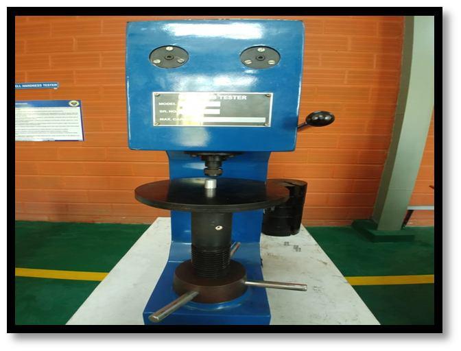
Brinell hardness number (BHN) is obtained by the ratio of the calculated load and the spherical area of the Indentation or Impression made on the specimen by the corresponding Indenter Ball. Brinell Hardness Test is used to determine the Hardness Number of hard, moderately hard, and soft material E.g.: Brass, Bronze, Aluminum, Gold, Copper, Etc. Figure 2.1 shows the Brinell hardness testing setup.
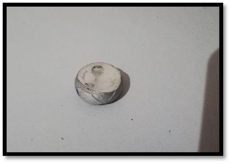
Fig.2.1 Brinell hardness testing setup Fig.2.2 Specimen used for Brinell hardness test and formation of indent on specimen
calculations involved in Brinell hardness testing are: Brinell Hardness Number (BHN) = 2P ……………………………...4.1
[D-√ ] Where;
Diameter of ball indenter in mm.
Diameter of Indentation in mm. P= Load applied in Kg F d=MSR+ (CVSD×LC). Least Count of Brinell Microscope=0.01mm.
ISSN: 2321-9653; IC Value: 45.98; SJ Impact Factor: 7.538 Volume 10 Issue XII Dec 2022- Available at www.ijraset.com
The procedure involved in calculating hardness is: Selecting the suitable indenter & weights according to the scale. Placing the specimen on testing table anvil. Turning the hand wheel to raise a job until it makes contact with indenter & turning till the longer pointer at the dial gauge makes 2 ½ rotations and turn the lever position from unloading to loading position. So that the total load will act. When the longer pointer of the dial gauge reaches steady position, take back the lever to the unloading position. Removing the job from the platform and note down the diameter of the indentation using Brinell microscope.
C. Using formula calculate BHN. The values obtained were used to calculate the Brinell hardness number of the specimen. The figure 2.2 shows the specimen used for Brinell hardness test and the indent formed on the surface of the specimen after the application of load.
TABLE.II
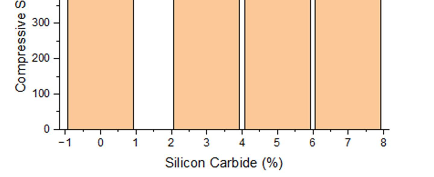
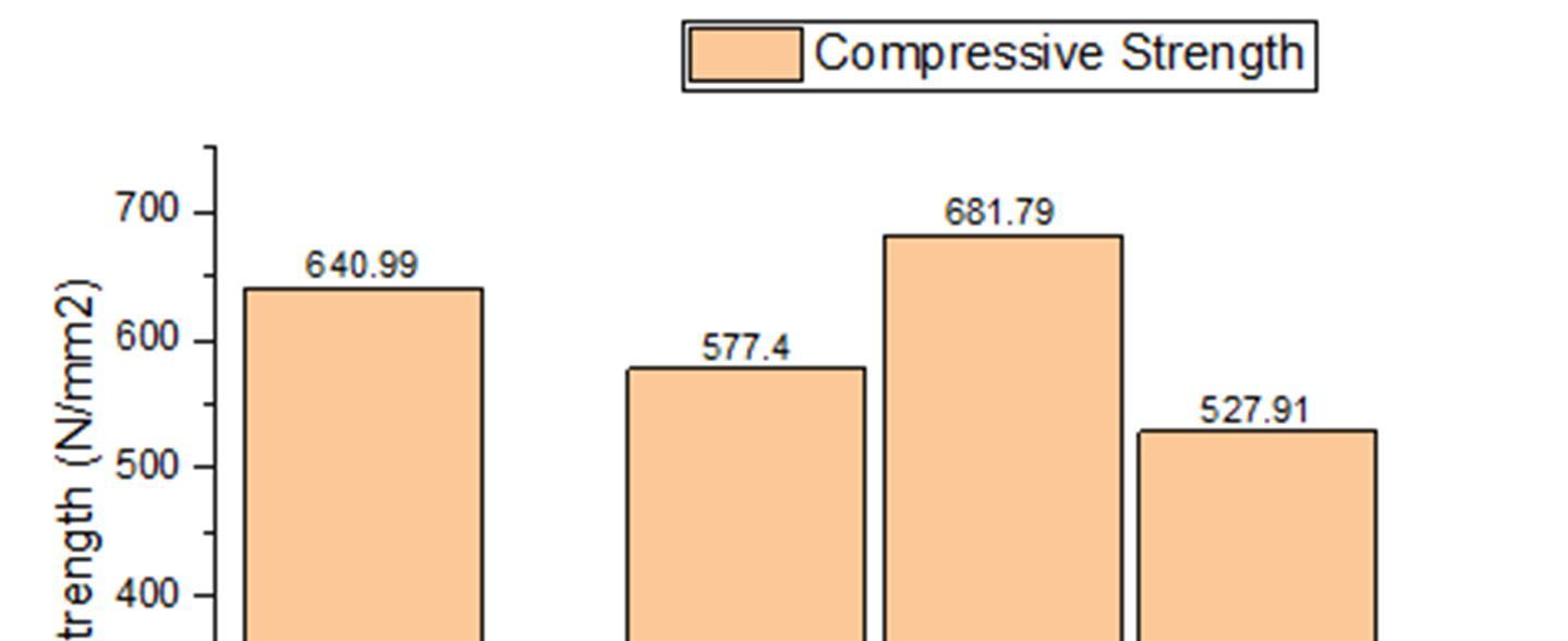
COMPRESSIVE STRENGTH OF AL8011 + 0% S-GLASS + VARYING % OF SILICON CARBIDE
% of S-glass fibre Varying % of Sic Compressive Strength in N/mm2 0 0 640.99 0 3 577.40 0 5 681.79 0 7 527.91
Fig.2.3 Compressive Strength of Al8011 + 0% S-glass + varying % of Silicon Carbide
The above bar chart shows the compression test of Al8011 for the various weight percentage combinations of silicon carbide such as 3%, 5% and 7%, for the combination of 5% weight percentage of silicon carbide with Al8011 shows 681.79 N/mm2 .
ISSN: 2321-9653; IC Value: 45.98; SJ Impact Factor: 7.538 Volume 10 Issue XII Dec 2022- Available at www.ijraset.com
TABLE. III
COMPRESSIVE STRENGTH OF AL8011 + 2% S-GLASS + VARYING % OF SILICON CARBIDE
% of S-glass fibre Varying % of Sic Compressive Strength in N/mm2 2 0 602.54 2 3 611.19 2 5 675.11 2 7 699.54
Fig.2.4 Compressive Strength of Al8011 + 2% S-glass + varying % of Silicon Carbide
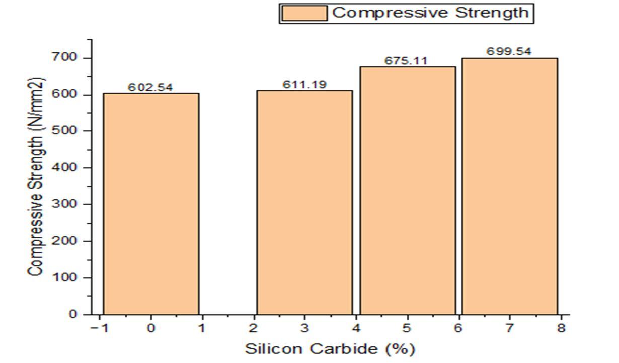
The above bar chart shows the compression test of Al8011 for the various weight percentage combinations of silicon carbide such as 3%, 5% and 7% and 2% of S-glass fibre, for the combination of 5% weight percentage of silicon carbide and 2% of S-glass fibre with Al8011 shows 699.54 N/mm2
TABLE.IV
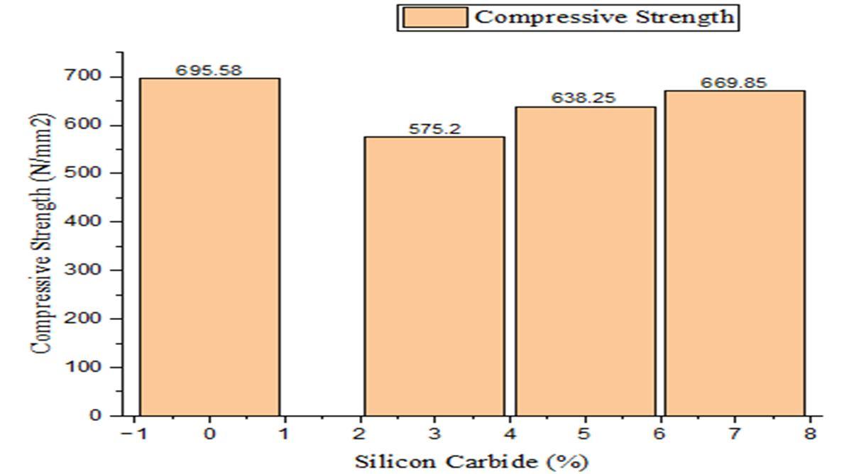
COMPRESSIVE STRENGTH OF AL8011 + 4% S-GLASS + VARYING % OF SILICON CARBIDE
% of S-glass fibre Varying % of Sic Compressive Strength in N/mm2 4 0 695.58 4 3 575.20 4 5 638.25 4 7 669.85
Fig.2.5. Compressive Strength of Al8011 + 2% S-glass + varying % of Silicon Carbide
ISSN: 2321-9653; IC Value: 45.98; SJ Impact Factor: 7.538 Volume 10 Issue XII Dec 2022- Available at www.ijraset.com
The above bar chart shows the compression test of Al8011 for the various weight percentage combinations of silicon carbide such as 3%, 5% and 7% and 4% of S-glass fibre, for the combination of 0% weight percentage of silicon carbide and 4% of S-glass fibre with Al8011 shows 695.58 N/mm2
TABLE. V
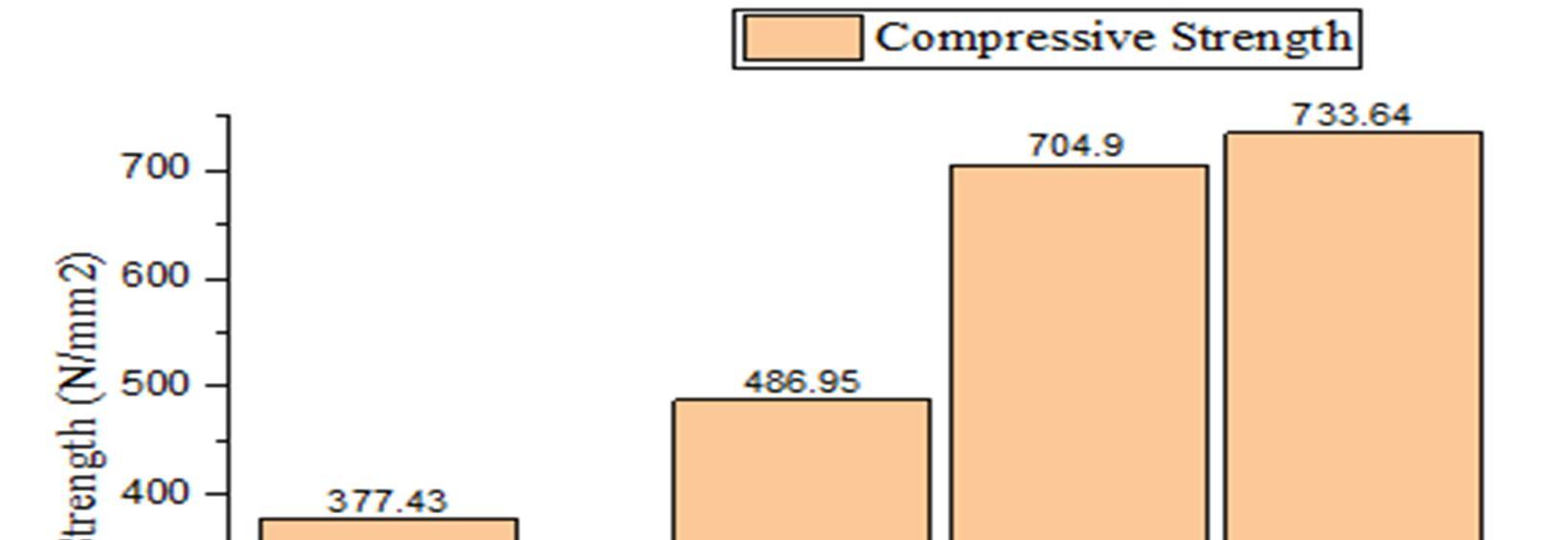
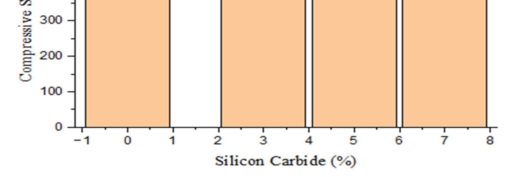
COMPRESSIVE STRENGTH OF AL8011 + 6% S-GLASS + VARYING % OF SILICON CARBIDE
% of S-glass fibre Varying % of Sic Compressive Strength in N/mm2 6 0 377.43 6 3 486.95 6 5 704.90 6 7 733.64
Fig.2.6 Compressive Strength of Al8011 + 6% S-glass + varying % of Silicon Carbide
The above bar chart shows the compression test of Al8011 for the various weight percentage combinations of silicon carbide such as 3%, 5% and 7% and 6% of S-glass fibre, for the combination of 7% weight percentage of silicon carbide and 6% of S-glass fibre with Al8011 shows 733.64 N/mm2
B. Hardness Test Results
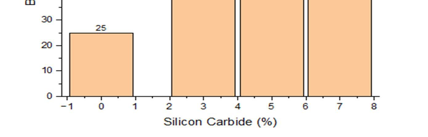
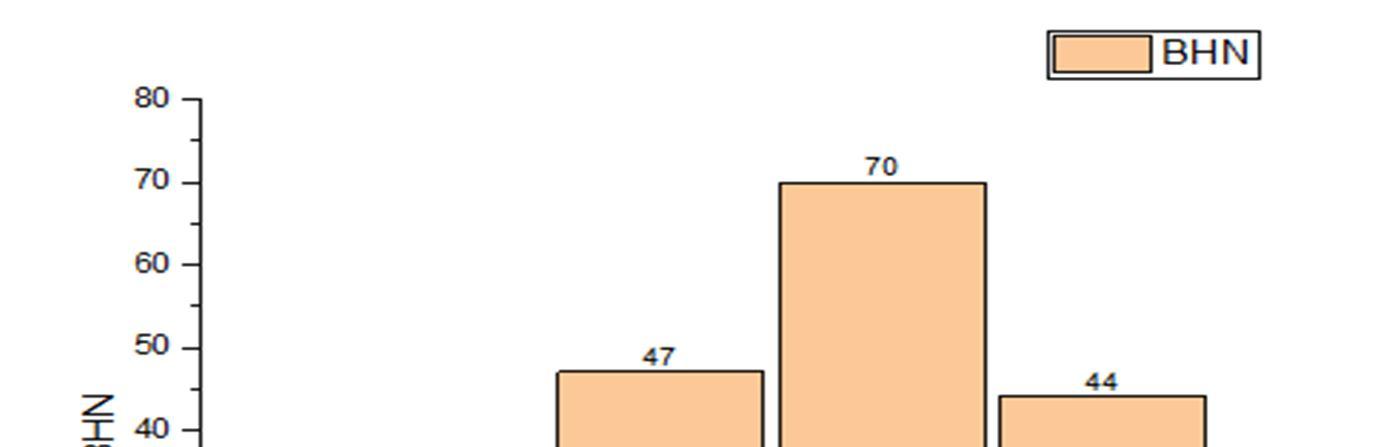
TABLE.VI. HARDNESS OF AL8011 + 0% S-GLASS + VARYING % OF SILICON CARBIDE
% of S-glass fibre Varying % of Sic Hardness (BHN) 0 0 25 0 3 47 0 5 70 0 7 44
ISSN: 2321-9653; IC Value: 45.98; SJ Impact Factor: 7.538 Volume 10 Issue XII Dec 2022- Available at www.ijraset.com
Fig.2.7. Hardness of Al8011 + 0% S-glass + varying % of Silicon Carbide
The above bar chart shows the hardness of Al8011 for the various weight percentage combinations of silicon carbide such as 3%, 5% and 7% and 0% of S-glass fibre, for the combination of 5% weight percentage of silicon carbide and 0% of S-glass fibre with Al8011 shows the maximum value 70 BHN.
TABLE.VI. HARDNESS OF AL8011 + 2% S-GLASS + VARYING % OF SILICON CARBIDE % of S-glass fibre Varying % of Sic Hardness (BHN) 2 0 50 2 3 36 2 5 37 2 7 38
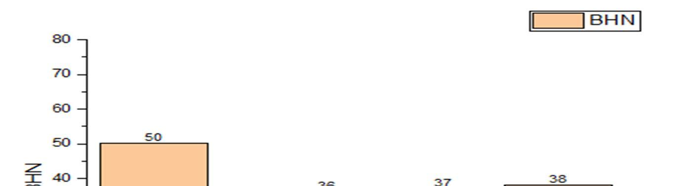
Fig.2.8. Compressive Strength of Al8011 + 2% S-glass + varying % of Silicon Carbide
The above bar chart shows the hardness of Al8011 for the various weight percentage combinations of silicon carbide such as 3%, 5% and 7% and 2% of S-glass fibre, for the combination of 0% weight percentage of silicon carbide and 2% of S-glass fibre with Al8011 shows the maximum of 50 BHN.
ISSN: 2321-9653; IC Value: 45.98; SJ Impact Factor: 7.538 Volume 10 Issue XII Dec 2022- Available at www.ijraset.com
TABLE.VII.HARDNESS OF AL8011 + 4% S-GLASS + VARYING % OF SILICON CARBIDE
% of S-glass fibre Varying % of Sic Hardness (BHN) 4 0 43 4 3 43 4 5 40 4 7 41
Fig.2.9. Compressive Strength of Al8011 + 4% S-glass + varying % of Silicon Carbide
The above bar chart shows the hardness of Al8011 for the various weight percentage combinations of silicon carbide such as 3%, 5% and 7% and 4% of S-glass fibre, for the combination of 0% weight percentage of silicon carbide and 4% of S-glass fibre with Al8011 shows the maximum of 43 BHN.
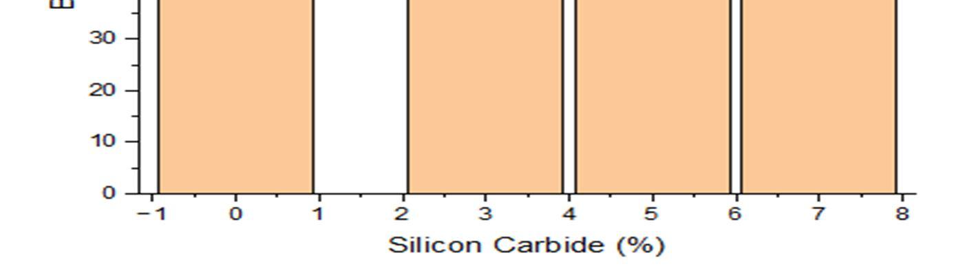
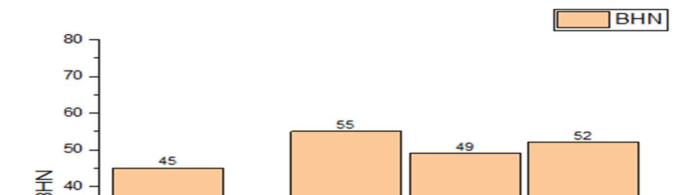
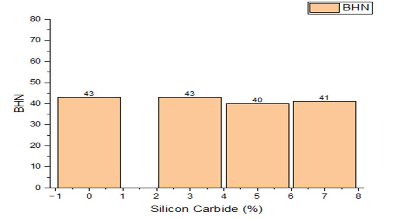
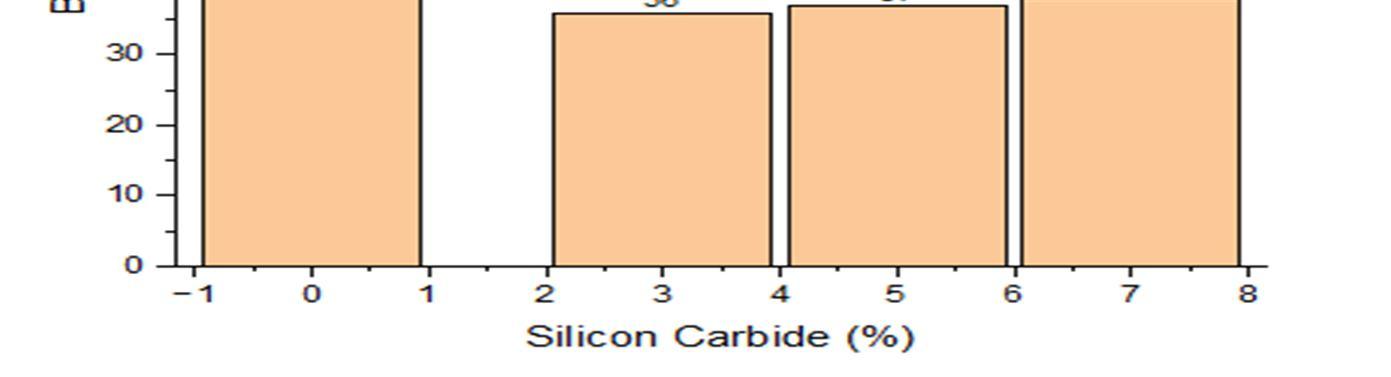
TABLE. VIII. HARDNESS OF AL8011 + 6% S-GLASS + VARYING % OF SILICON CARBIDE
% of S-glass fibre Varying % of Sic Hardness (BHN) 6 0 45 6 3 55 6 5 49 6 7 52
Fig.2.10. Compressive Strength of Al8011 + 2% S-glass + varying % of Silicon Carbide
ISSN: 2321-9653; IC Value: 45.98; SJ Impact Factor: 7.538 Volume 10 Issue XII Dec 2022- Available at www.ijraset.com
The above bar chart shows the hardness of Al8011 for the various weight percentage combinations of silicon carbide such as 3%, 5% and 7% and 6% of S-glass fibre, for the combination of 3% weight percentage of silicon carbide and 6% of S-glass fibre with Al8011 shows the maximum of 55 BHN.
Among all the combination of aluminium, silicon carbide and S-glass fibre, the maximum value of compression strength is shown for the combination of 7% weight percentage of silicon carbide and 6% of S-glass fibre with Al8011 of 733.64 N/mm2, whereas the lowest value of 377.43 N/mm2 was of observed for the combination of 6% of S-glass fibre and 0% of Silicon fibre with Al8011. In the hardness test evaluation, the combination of 5% silicon carbide and 0% S-glass fibre with aluminium 8011 has a hardness value 70 BHN, in opposite to this highest value of BHN, the lowest value of 36 BHN was observed for the combination of 2% Sglass fibre and 3% silicon carbide with Al8011
[1] T R Mohan, C M Sharanaprabhu and Shashidhar K Kudari “Study on The Effects of SSic Particles on Tensile Properties for Al/Sic Composites”, International Journal of Science, Technology and Management, Vol 04, Special Issue No. 01, March 2015, pp 1477-1483.
[2] Mr. A. R. Dhatrak and Dr. K. B. Kale. “Wear Rate Investigation of Aluminium Based Silicon Carbide Metal Matrix Composite Embedded with Copper”, IJIRST –International Journal for Innovative Research in Science & Technology, Volume 3, Issue 04, September 2016. Pp 376-384
[3] M. Asif*, K. Chandra and P.S. Misra. “Development of Aluminium Based Hybrid Metal Matrix Composites for Heavy Duty Applications” Journal of Minerals & Materials Characterization & Engineering, Vol. 10, No.14, pp.1337-1344, 2011
[4] Frederick T. Wallenberger, James C. Watson, and Hong Li “Glass Fibers”, ASM International. All Rights Reserved. ASM Handbook, 2015, Vol. 21, PPG Industries, Inc.
[5] A. Elanthiraiyan*, G. Antony Casmir Jayaseelan, S. Ashok Kumar And S. Sathiyaraj, “Investigation Of Machining Characteristics Of Aluminium 8011 By Wire Cut Ed.M. Process”, Department of Mechanical Engineering, Aarupdai Veedu Institute of Technology, Vinayaka Missions University, Chennai (T.N.) India. Vol 4, pp 3119-3130, 2016.
[6] Neelima Devi. C, Mahesh. V and Selvaraj. N, “Mechanical characterization of Aluminium silicon carbide composite”, International Journal Of Applied Engineering Research, Dindigul Volume 1, No 4, 2011, pp 1642-1649
[7] A. O. Inegbenebor, C. A. Bolu, P. O. Babalola, A. I. Inegbenebor , O. S. I. Fayomi.”Aluminum Silicon Carbide Particulate Metal Matrix Composite Development Via Stir Casting Processing” Springer Science Business Media Dordrecht 2016, 1 August 2016, pp 9451-9458