
ISSN: 2321-9653; IC Value: 45.98; SJ Impact Factor: 7.538 Volume 11 Issue I Jan 2023- Available at www.ijraset.com


ISSN: 2321-9653; IC Value: 45.98; SJ Impact Factor: 7.538 Volume 11 Issue I Jan 2023- Available at www.ijraset.com
Abhinav Gupta1, Dr. Uttam Awari2
1P.G. Student, Dept. of Civil Engineering, AISSMS College of Engineering, Pune, India 2Prof. Dept. of Civil Engineering, AISSMS College of Engineering, Pune, India

Abstract: The provision of transverse openings in floor beams to facilitate the passage of utility pipes and service ducts results not only in a more systematic layout of pipes and ducts, it also translates into substantial economic savings in the construction of a multi-storey building. To investigate the problem of openings in beams, the author initiated a research program in the early 1980s. Since then extensive research has been carried out giving a comprehensive coverage on both circular and large rectangular openings under various combinations of bending, shear and torsion. In this paper, major findings relevant to the analysis and design of such beams under the most commonly encountered loading case of bending and shear are extracted and summarized. An attempt has been made to answer the frequently asked questions related to creating an opening in an already constructed beam and how to deal with multiple openings. It has been shown that the design method for beams with large openings can be further simplified without sacrificing rationality and having unreasonable additional cost. In this research work, we analyzed the effect of position of opening in RCC beams subjected to combined flexure and shear by checking their effects on the shear and bending behavior of the beams. The considered parameters for the study are loaddeflection curve, the shape of the cracks, and the stress distribution. Grade of concrete taken as M-25. Cross-section of reinforced concrete beam is 0.15 x 0.15 x 0.70 m with circular opening of 0.09 m diameter is considered. In this study, total five numbers of specimens were tested. The parameters are: Two types of specimens considered as without opening and three types of specimens considered as with Opening at different locations, In one specimen we took opening at the left corner of beam and in other specimen, we took opening at the right corner of the beam and In One specimen we took opening in both the corners. Stirrups were used in this study to get more accurate result. The results were validated by compare the experimental test results by UTM against the software analysis results using ANSYS software and we found that reinforced concrete beams with openings of different horizontal location and reported that placing holes in flexure zone has lesser impact on the beam performance compared to when the castellation are placed in the shear zone. This study is focused on the flexure and shear behavior of beam with different openings and their parameters like Deformation, Load-Deflection, and Crack Pattern.
Keywords: UTM, Openings, Ansys, Flexure zone, Shear zone.
In the construction of modern buildings, a network of pipes and ducts is necessary to accommodate essential services like water supply, sewage, air-conditioning, electricity, telephone, and computer network. Usually, these pipes and ducts are placed underneath the beam soffit and, for aesthetic reasons, are covered by a suspended ceiling, thus creating a dead space. Passing these ducts through transverse openings in the floor beams leads to a reduction in the dead space and results in a more compact design. For small buildings, the savings thus achieved may not be significant, but for multistory buildings, any saving in story height multiplied by the number of stories can represent a substantial saving in total height, length of air-conditioning and electrical ducts, plumbing risers, walls and partition surfaces, and overall load on the foundation.
It is obvious that inclusion of openings in beams alters the simple beam behavior to a more complex one. Due to abrupt changes in the sectional configuration, opening corners are subject to high stress concentration that may lead to cracking unacceptable from aesthetic and durability viewpoints. The reduced stiffness of the beam may also give rise to excessive deflection under service load and result in a considerable redistribution of internal forces and moments in a continuous beam. Unless special reinforcement is provided in sufficient quantity with proper detailing, the strength and serviceability of such a beam may be seriously affected.
In previous extensive experimental study, considered openings of circular, rectangular, diamond, triangular, trapezoidal and even irregular shapes. However, circular and rectangular openings are the most common ones in practice. When the size of opening is concerned, many researchers use the terms small and large without any definition or clear-cut demarcation line.
ISSN: 2321-9653; IC Value: 45.98; SJ Impact Factor: 7.538 Volume 11 Issue I Jan 2023- Available at www.ijraset.com
From a survey of available literature, it has been noted that the essence of such classification lies in the structural response of the beam. When the opening is small enough to maintain the beam-type behavior or, in other words, if the usual beam theory applies, then the opening may be termed as small opening. Ideally, services pipes shall be run under the beams. However, clients and services consultants do not prefer this situation many times. Pipes will have to bend; Floor height will reduce. You can think of a 20-floor building and the builder getting approval for 60m height for building. A 150mm pipe in all levels will eat up 3m of the total building and this means he loses 1 floor and this means the builder loose an opportunity to sell a floor.
If the coring damages the existing reinforced rebar it can damage the structural performance of the element. First try to understand meaning of ‘Reinforcement’; It is a term which has come from military which means to impart extra strength or extra force. Similarly in concrete,
1) Concrete is very poor in taking tensile strength about 10% of its compressive strength so we need to reinforced it with reinforcement bars called Rebars to take tensile stresses & excessive compressive & shear stresses.
2) Reinforcement bars also take care of creep & shrinkage stresses.
3) We know concrete is a brittle material, it will fail immediately without any warning but Reinforcement (steel bars) are ductile in nature and will give ample of warning before failure.
4) Also, Rebar’s prevent the propagation of cracks.
Nowadays, tubular constructions have become increasingly prevalent in tall buildings. Tube in tube structures is ideally suited for any tall structures. A tube-in- tube structure consists of a framed peripheral tube and a core tube that are joined by floor slabs. The overall structure resembles a large tube with a smaller tube in the centre. Both the inner and outer tubes share lateral loads. This paper includes an investigation of the vulnerability of different tubed structures to large wind loads when built as tube-in- tube structures and bundled tube structures. Tube-in-tube structures and bundled tube structures are unique and novel tubular structure concepts. In this project, ETABS software was used to conduct a comparison of tube- in-tube structure and bundled tube structures. Using ETABS, the modelling and analysis are performed.
Based on the literature review presented in Chapter 2, the salient objectives of the Present study have been identified as follows The objectives of proposed work are as follows:
1) To analyse the effect of position of opening in RCC beams subjected to combined flexure and shear.
2) Parameters Are: Load - Directional Deformation, Crack Patterns, Principal Stresses.
3) Comparative analysis between Software (ANSYS) and Experiment by using UTM 4) To compare results between the models with respect to Flexure and Shear
This research work aimed to know the effect of the openings in the beams by checking their parameters- effects on the shearing and bending behaviour of the beams with a load-deflection curve, the shape of the cracks, and the stress distribution to prevent damage. This will be validated by comparing the experimental test results against the software analysis results using the ANSYS software.
In this study of Experimental and Software both analysis were carried out with total five numbers of beam specimens of size 0.15 x 0.15 x 0.70 m casted after 28 days of curing. Out of which two types of specimens considered as without opening and three types of specimens considered as with Opening of 0.09 m in diameter at different locations, we provide PVC pipe of 90mm diameter for the circular castellation in beam. In One specimen, we took opening at the left corner of beam and in other specimen, we took opening at the right corner of the beam and In One specimen we took opening in both the corners. Stirrups were used in this study to get more accurate result. The result were validated by compare the experimental test results against the software analysis results using ANSYS software, In second phase of methodology of the experimentation works includes provision of reinforcement in beam having 4 bars of 10mm diameter at the corner of beams with flexural strength of 500 MPa with 8mm stirrups @ 100 C/C with flexural strength 280 MPa, after that calculations of cutting and moulding length of reinforcing bars and stirrups are done with respect to IS 2502- 1963.

ISSN: 2321-9653; IC Value: 45.98; SJ Impact Factor: 7.538 Volume 11 Issue I Jan 2023- Available at www.ijraset.com

Now provided pvc pipe of 90mm diameter for openings in beam. In the third phase of experimentation work, we were taken Mix design of the M-25 grade concrete to cast all the 5 beams in accordance with the IS-456:2000. Casted 3 cubes for checking compressive strength of concrete for 28 days. Shows in Table 3.3
Table 3.3: Nomenclature of Casted Cubes
Sr. No. Notation No. of Specimens Compression Test 28 (Days)
1 Cube 1 1 740 KN/M2
2 Cube 2 1 880 KN/M2
3 Cube 3 1 958.65 KN/M2
After provided 28 days of curing for all the specimens of beam, Fourth phase includes the testing of all 5 specimens the beams are tested for Flexure and Shear by using UTM (Universal Testing Machine) Machine, after testing the specimens the analysis of the result is carried out. The comparison analysis of the beams was carried out for all the parameters. The parameter Includes Load & deflection, Crack patterns and stress distribution. In fifth Phase 1st we created Software model’s geometry in Metric units which includes Beams, Rebar, Stirrups, Openings, Supports and Impactor, After that provided all the properties for respective members:Rebar 4 bars of 10mm diameter with 8mm stirrups @ 100 C/C with 550 MPA, Young’s Modulus 2E+05, Poison’s ratio 0.3, size of beam- 0.15 x 0.15 x 0.70 m, Opening taken as 0.90 m diameter. After provided all the inputs to the software we were analysed all the 5 beam specimens for Load deflection curve, crack patterns and stress distribution.
In this Experimental analysis were carried out with total five numbers of beam specimens of size 0.15 x 0.15 x 0.70 m casted for 28 day. Out of which two types of specimens considered as without opening and three types of specimens considered as with Opening of 0.09 m in diameter at different locations, In One specimen we took opening at the left corner of beam and in other specimen we took opening at the right corner of the beam and In One specimen we took opening in both the corners and Stirrups were also used in this study to get more accurate result.
Steel reinforcement are steel bars that are provided in combination with plain cement concrete to make it reinforced concrete.
Provided Rebar- four bars of 10mm diameter are used for main and distribution reinforcement with 8mm stirrups @ 100 C/C. as shown in fig 4.4.1

Max. Allowed spacing = .75 x d (effective depth)
Max. Allowed spacing = 97.5 mm, so considered 100mm spacing C/C
Total number of stirrups = (Beam Length / Spacing) + 1
Total number of stirrups = (700/100) + 1 = 8 Nos
PVC pipe of 90mm diameter are provided for openings in beam.
ISSN: 2321-9653; IC Value: 45.98; SJ Impact Factor: 7.538 Volume 11 Issue I Jan 2023- Available at www.ijraset.com

It is a temporary structure, which is used as a mould to pour the concrete. It is a vertical or horizontal arrangement made to keep concrete in position until it gains strength & shape. As shown in fig: 4.4.2 (a) & (b)

Fig 4.4.2 (a) Formwork
Beam 2 (B2) Beam 4 (B4) Beam 5 (B5)
Beam 3 (B3)
Beam 1 (B1) Without Opening Without Opening Opening at the left corner Opening at the Right corner Opening in both the corners
Fig 4.4.2 (b) Formwork
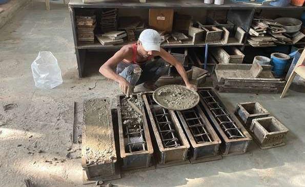
To place concrete in proper way, care must be taken to make preparations before placing. Inner surface of all moulds are clean thoroughly. Oil is applied to all the inner surface of beam moulds to get smooth surface. The fresh concrete is placed in moulds by trowel. It is ensure that the respective volume is filled evenly in all the moulds to avoid segregation of aggregate. Concrete specimens are casted in three layers. Each layers is well compacted. All the moulds are too filled completely to the top and has to be well compacted to ensure that no honey combing is occurred in specimen, Date of Casting 23.11.2022. Shown in fig. 4.4.3

ISSN: 2321-9653; IC Value: 45.98; SJ Impact Factor: 7.538 Volume 11 Issue I Jan 2023- Available at www.ijraset.com

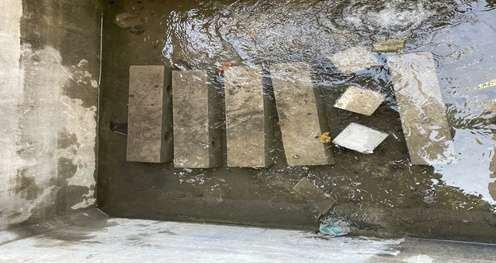
Concrete placed in mould of concrete are allowed to settle for 24 hours, After 24 hours, de-moulding of concrete specimens is done. Care should be taken that, during removal of specimens from mould there should not be any damage to the corners of specimen. After de-moulding, specimens are placed to the curing tank, Normal curing is carried out throughout the experimental program for a period of 28 days. Shown in fig. 4.4.4 (a) & (b)
Fig. 4.4.4 (a) De-moulding of Beams
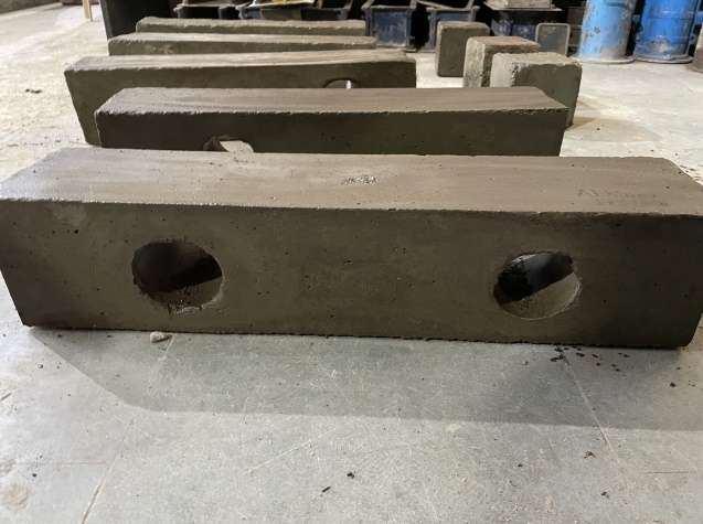
Fig. 4.4.4 (b) Curing of Specimens
The testing of specimen is carried out after the curing of the concrete specimen is over after 28 days. In total 5 beams are casted for this experimental program. The Flexure test on the entire specimen was carried out on 22nd December 2022 for the load–deflections & crack patterns. Three Cubes are also casted for compression test, which are also done in UTM.

ISSN: 2321-9653; IC Value: 45.98; SJ Impact Factor: 7.538 Volume 11 Issue I Jan 2023- Available at www.ijraset.com


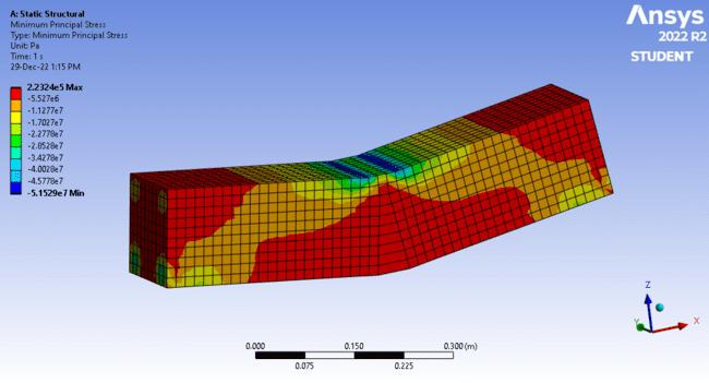
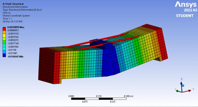
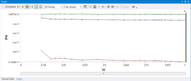
Minimum Principal Stress
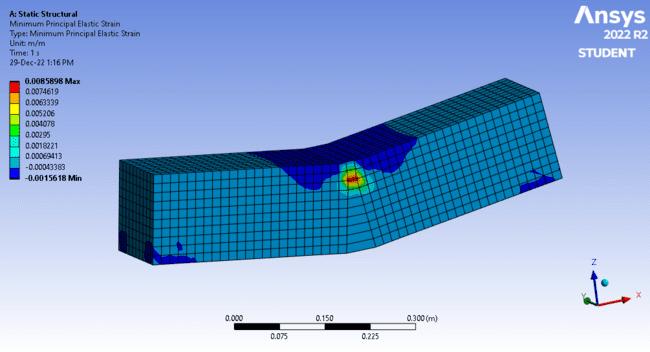
Minimum Principal Elastic Strain
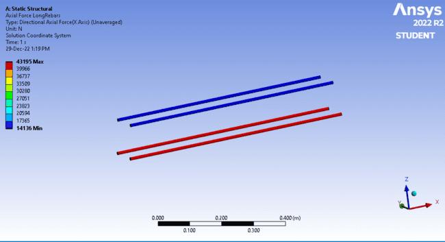
Axial Force Long Rebar
ISSN: 2321-9653; IC Value: 45.98; SJ Impact Factor: 7.538 Volume 11 Issue I Jan 2023- Available at www.ijraset.com

Graph 6.3.1 (b) Minimum Principal Stress B1 & B2
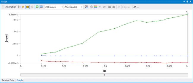
Graph 6.3.1 (c) Minimum Principal Elastic Strain B1 & B2
ISSN: 2321-9653; IC Value: 45.98; SJ Impact Factor: 7.538 Volume 11 Issue I Jan 2023- Available at www.ijraset.com

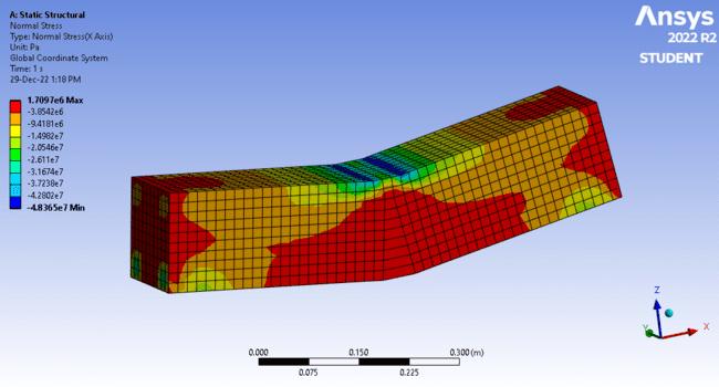
Fig 6.3.1 (d) Normal Stress B1 & B2
Graph 6.3.1 (d) Normal Stress B1 & B2

Fig 6.3.1 (e) Axial Force Long Rebar B1 & B2

ISSN: 2321-9653; IC Value: 45.98; SJ Impact Factor: 7.538 Volume 11 Issue I Jan 2023- Available at www.ijraset.com
Graph 6.3.1 (e) Axial Force Long Rebar B1 & B2
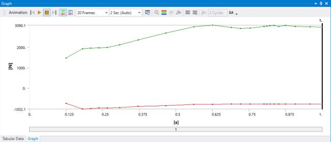

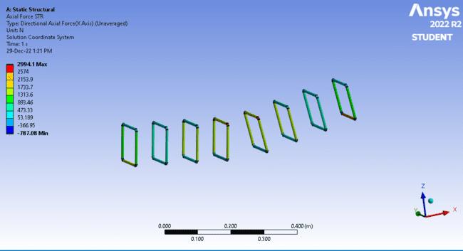
Fig 6.3.1 (f) Axial Force Stirrups B1 & B2
Graph 6.3.1 (f) Axial Force Stirrups B1 & B2

ISSN: 2321-9653; IC Value: 45.98; SJ Impact Factor: 7.538 Volume 11 Issue I Jan 2023- Available at www.ijraset.com
B3 Beams is considered as beam with opening at left corner.
Fig. 6.3.2 (a) Directional Deformation of Beam B3
Graph 6.3.2 (a) Directional Deformation of Beam B3
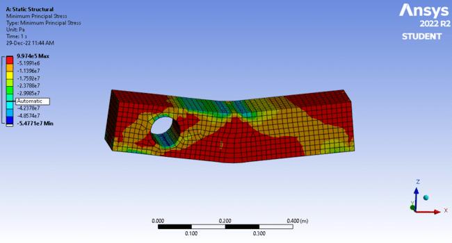
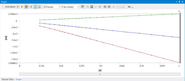
Fig. 6.3.2 (b) Minimum Principal Stress B3


ISSN: 2321-9653; IC Value: 45.98; SJ Impact Factor: 7.538 Volume 11 Issue I Jan 2023- Available at www.ijraset.com
Graph 6.3.2 (b) Minimum Principal Stress B3
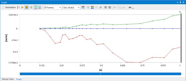
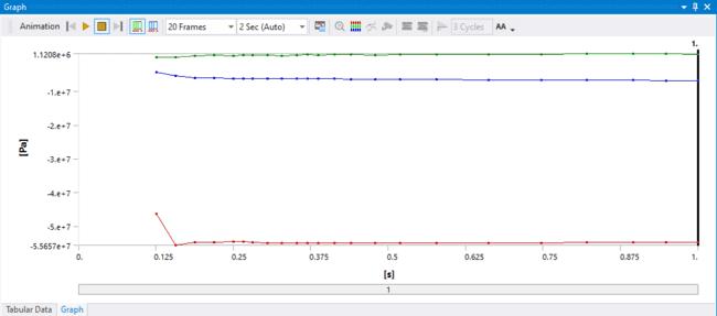
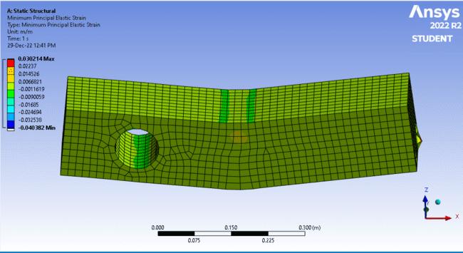
Fig. 6.3.2 (c) Minimum Principal Elastic Strain B3
Graph. 6.3.2 (c) Minimum Principal Elastic Strain B3
ISSN: 2321-9653; IC Value: 45.98; SJ Impact Factor: 7.538 Volume 11 Issue I Jan 2023- Available at www.ijraset.com

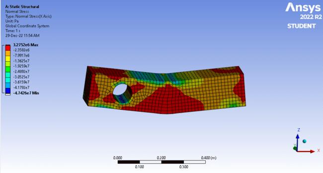
Fig. 6.3.2 (d) Normal Stress B3
Graph 6.3.2 (d) Normal Stress B3
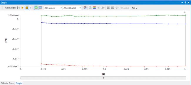
Fig. 6.3.2 (e) Axial Force Long Rebar B3


ISSN: 2321-9653; IC Value: 45.98; SJ Impact Factor: 7.538 Volume 11 Issue I Jan 2023- Available at www.ijraset.com
Graph 6.3.2 (e) Axial Force Long Rebar B3
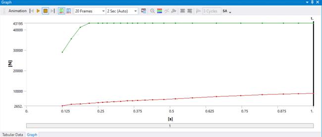
Fig. 6.3.2 (f) Axial Force Stirrups B3

Graph 6.3.2 (f) Axial Force Stirrups B3

B4 Beams is considered as beam with opening at Right corner.
ISSN: 2321-9653; IC Value: 45.98; SJ Impact Factor: 7.538 Volume 11 Issue I Jan 2023- Available at www.ijraset.com

Fig. 6.3.3 (a) Directional Deformation of Beam B4
Graph 6.3.3 (a) Directional Deformation of Beam B4
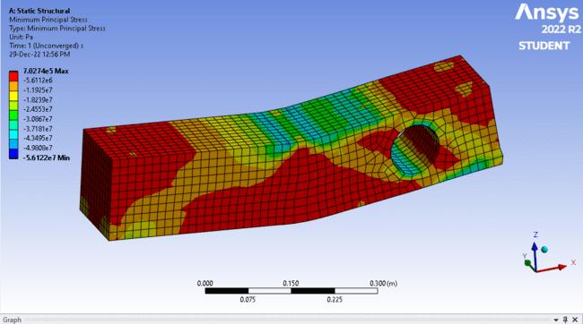
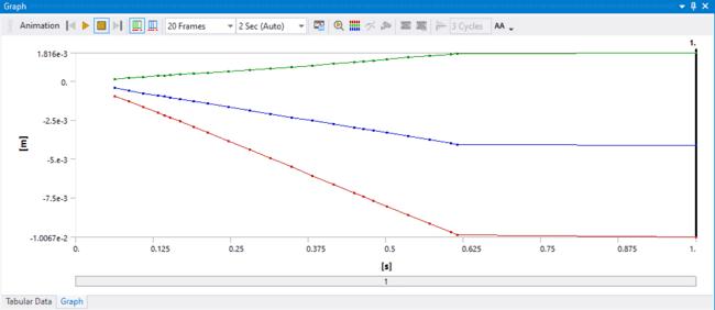
Fig. 6.3.3 (b) Minimum Principal Stress Beam B4

ISSN: 2321-9653; IC Value: 45.98; SJ Impact Factor: 7.538 Volume 11 Issue I Jan 2023- Available at www.ijraset.com

Graph 6.3.3 (b) Minimum Principal Stress Beam B4
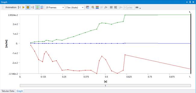
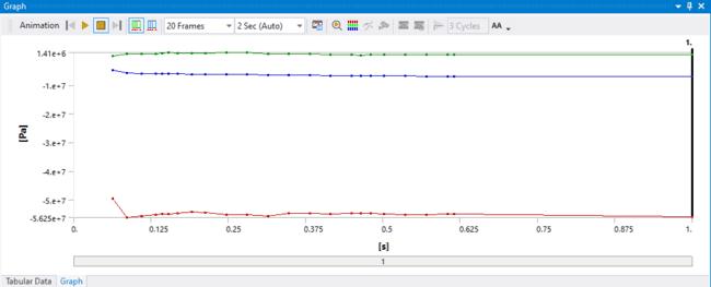
Fig. 6.3.3 (c) Minimum Principal Elastic Strain Beam B4
Graph 6.3.3 (c) Minimum Principal Elastic Strain Beam B4
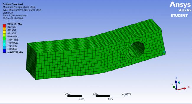
ISSN: 2321-9653; IC Value: 45.98; SJ Impact Factor: 7.538 Volume 11 Issue I Jan 2023- Available at www.ijraset.com

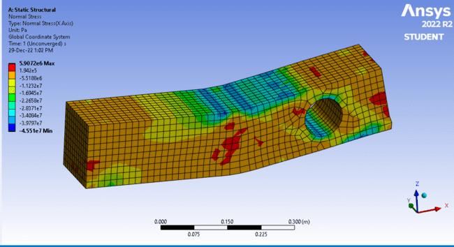
Fig. 6.3.3 (d) Normal Stress Beam B4
Graph 6.3.3 (d) Normal Stress Beam B4
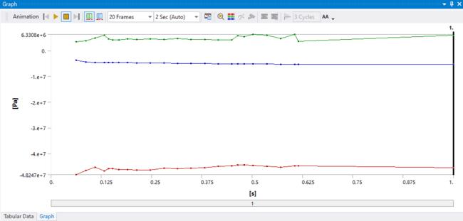
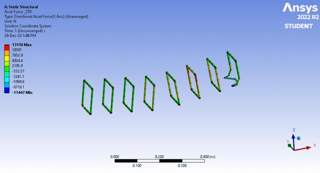
Fig. 6.3.3 (e) Axial Force Long Rebar Beam B4



ISSN: 2321-9653; IC Value: 45.98; SJ Impact Factor: 7.538 Volume 11 Issue I Jan 2023- Available at www.ijraset.com
Graph 6.3.3 (e) Axial Force Long Rebar Beam B4
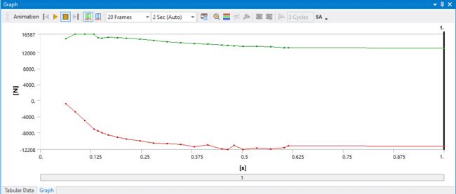
Fig. 6.3.3 (f) Axial Force Stirrups Beam B4 6.3.3 (f) Axial Force Stirrups Beam B4

ISSN: 2321-9653; IC Value: 45.98; SJ Impact Factor: 7.538 Volume 11 Issue I Jan 2023- Available at www.ijraset.com
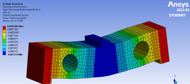
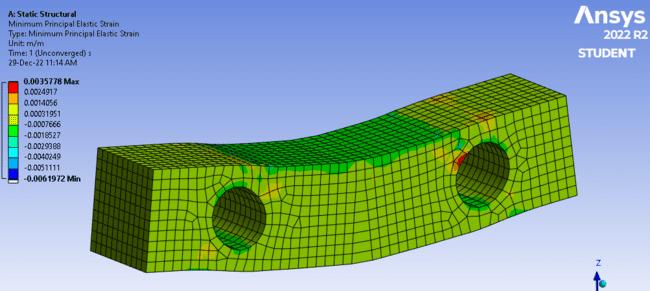
Beam with opening on both the corners.
Fig 6.3.4 (a) Directional Deformation of Beam B5
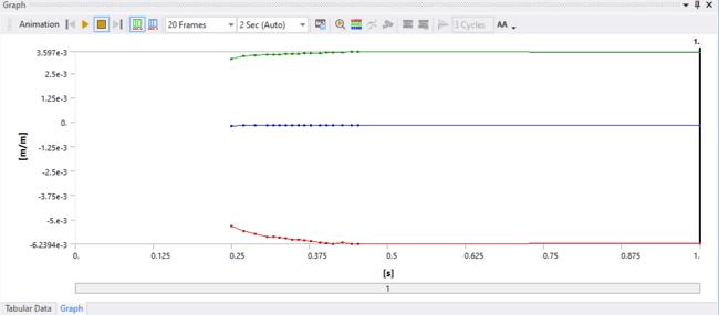
Graph 6.3.4 (a) Directional Deformation of Beam B5


Fig 6.3.4 (b) Minimum Principal Stress of Beam B5
ISSN: 2321-9653; IC Value: 45.98; SJ Impact Factor: 7.538 Volume 11 Issue I Jan 2023- Available at www.ijraset.com


ISSN: 2321-9653; IC Value: 45.98; SJ Impact Factor: 7.538 Volume 11 Issue I Jan 2023- Available at www.ijraset.com

Fig 6.3.4 (d) Normal Stress of Beam B5
Graph 6.3.4 (d) Normal Stress of Beam B5

Fig 6.3.4 (e) Axial Force Long Rebar of Beam B5


ISSN: 2321-9653; IC Value: 45.98; SJ Impact Factor: 7.538 Volume 11 Issue I Jan 2023- Available at www.ijraset.com
Graph 6.3.4 (e) Axial Force Long Rebar of Beam B5
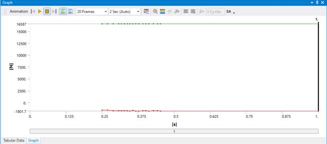
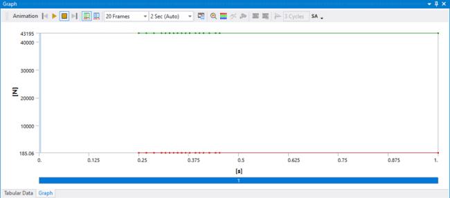
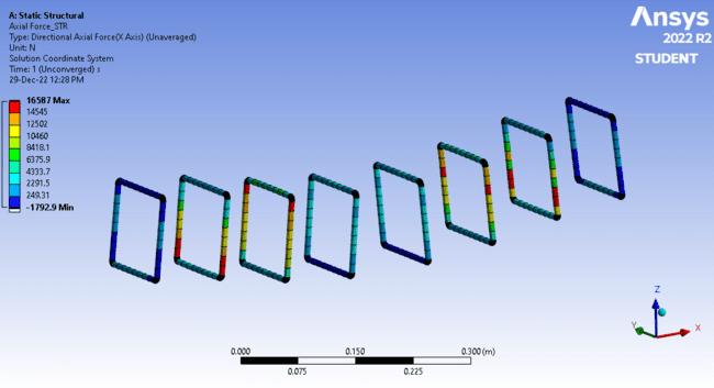
Fig 6.3.4 (f) Axial Force Stirrups of Beam B5
Graph 6.3.4 (f) Axial Force Stirrups of Beam B5
ISSN: 2321-9653; IC Value: 45.98; SJ Impact Factor: 7.538 Volume 11 Issue I Jan 2023- Available at www.ijraset.com
This is the comparison of Flexure deformation between Experimental and Software Result.
Table 6.1 Comparison between Experimental and Software Result
Sr. No Beam no. Experimental Software Max. Deformation Load in KN Max. Deformation
1 B1 2.81 100.5 2.689 2 B2 2.61 100.5 2.689 3 B3 2.62 49.55 2.764 4 B4 6.20 49.55 1.816 5 B5 7.09 42.45 1.03
The effects of opening transverse direction in reinforced concrete beams have been studied. In this research, we observe that reinforced concrete beams with openings of different horizontal location and reported that placing holes in flexure zone has lesser impact on the beam performance compared to when the castellation are placed in the shear zone. Based on the vigorous effort made in this area the following conclusions are drawn:
1) It could be concluded that the usage of circular-shaped openings is more effective than other shapes of openings since it avoids sharp edges, which are subjected to high-stress concentration while loading.
2) It is recommended to have a circular opening less than 0.55 D of the beam for web opening. The size of the opening to be restricted within 0.5D of the beam. The other shapes of web opening; Increase in size of opening decreases the mechanical properties of the beam, and it leads to the change in the mode of failure.
3) It can be concluded that, for web opening in RC beams, the optimum position to have opening at mid-depth and the center between the support and load point to reduce the changes made in the beam due to opening.
4) When the opening location moves towards the point of application of load or towards the support, there will be an occurrence of reduction in its load-carrying capacity.
5) It is proposed to select the strengthening materials based on the purpose, availability, cost, availability of skilled labor and time.
[1] Amiri, S., R. Masoudnia, Investigation of the Opening Effects on the Behavior of Concrete Beams Without Additional Reinforcement in Opening Region Using Fem Method, Australian Journal of Basic and Applied Sciences, 5(5),2011, 617-624.

[2] Hanson, J.M., Square openings in webs of continuous Joists, Portland Cement Association, 1969, pp: l-14.
[3] Somes, N.F. and W.G. Corley, Circular openings in webs of continuous beams, American Concrete Institute, Detroit, MI, 1974, pp: 359-398.
[4] Salam, S.A., Beams with openings under different stress conditions, Conference on Our World in Concrete and Structures, Singapore, 25-26 Aug, 1977, pp: 259-267.
[5] ANSYS, ANSYS User’s Manual Release 11, ANSYS, Inc.
[6] M. A. Mansur, S K Ting and S Lee , “Torsion Tests of R/C Beams With Large Openings”, J. Struct. Eng., 1983, pp 1780-1791
[7] Naik N, Kumar R and Rajaiah K, "Optimum Hole Shapes in Beams under Pure Bending." J. Eng. Mech., Vol 112, 1986, pp 407-411.
