10 VIII August 2022 https://doi.org/10.22214/ijraset.2022.46501

The VCRC i.e. Vapor Compression Refrigeration Cycle is one of the most widely used cycle in the field of refrigeration and air conditioning. The major components of this system are compressor, condenser, expansion and evaporator, etc. Out of these components the expansion device plays an important role. In vapor compression refrigeration system the capillary tubes used for the expansion purpose are only used in the helical form. Capillary tubeis a copper tube of very small internal diameter is one of the most commonly used throttling devices in the domestic refrigerators, air conditioning system, Water coolers and freezers. It is of very long length coiled to several turns so it would occupy less space.
1Department of Mechanical Engineering, Himanchal Institute of Engineering and Techonology, Shahpur Kangra (176052), India 2, 3Department of computer Engineering, Himanchal Institute of Engineering and Techonology, Shahpur Kangra (176052), India The main aim of this experimental study was to check the coefficient of performance on the Vapour Compression Refrigeration System by changing the shape of the capillary tube and by changing the refrigerants. Investigated the effect of Nano Refrigerant on the Coefficient Of Performance of Vapour Compressor Refrigeration Cycle. Compared the Coefficient Of Performance on the basis of R-22 (Difluoro-Monochloro Methane (CHF2CL) or R-22) and Al2O3 Nano particles mixed R22.The shape of the capillary tubes and the refrigerants is altered to study its effect on the performance of vapour compression refrigeration cycle. The shapes of Capillary tubes used were Serpentine Shape and Cubic Shape.
Abstract:
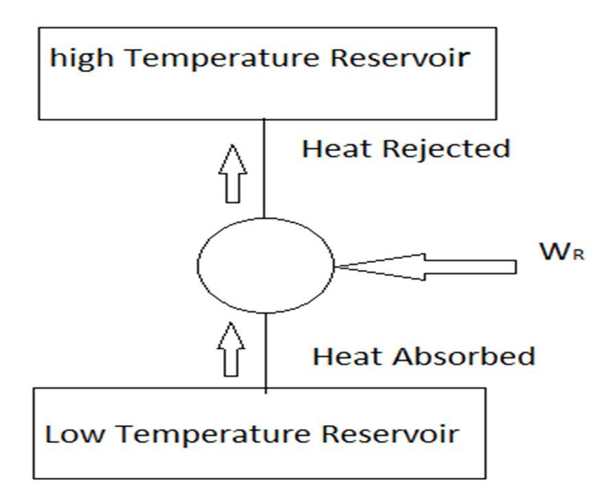
Fig. 1: Refrigeration System
I. INTRODUCTION
International Journal for Research in Applied Science & Engineering Technology (IJRASET) ISSN: 2321 9653; IC Value: 45.98; SJ Impact Factor: 7.538 Volume 10 Issue VIII Aug 2022 Available at www.ijraset.com 1740©IJRASET: All Rights are Reserved | SJ Impact Factor 7.538 | ISRA Journal Impact Factor 7.894 | Effect of Capillary Tube Shapes on The Performance of Vapour Compression Refrigeration Cycle Using Nano-Refrigerant
II. REFRIGERATION SYSTEM Refrigeration is the purpose being to cool some product or space to the required temperature and it is the process of attaining and maintaining a temperature lower that of the surroundings. Vapor compression refrigeration is the most widely used method for air conditioning of public houses, workplaces, private residences, hotels, hospitals, theaters, eateries and automobiles. It is also used in large scale warehouses for chilled or frozen storage of foods and meats, domestic and commercial refrigerators, refrigerated trucks and railroad cars, and a host of other commercial and industrial services. Air Conditioning denotes the treatment of air so as to control its temperature, moisture content, cleanliness and circulation, a process or products in the space.
Pankaj Dhiman1 , Dushyant Kaistha2 , Shabnam Dhiman3


A. Compression
Fig.4: Compressor B. Condensation
Fig. 2: Simple Vapour Compression Cycle
The vapour refrigerant at low pressure p1 and temperature T1 is compressed isentropically to dry saturated vapour as shown by the vertical line 1 2 on T s diagram and by the curve 1 2 on P h diagram. The pressure increases from p1 to p2and temperature from T1 to T2 respectively. The work done during isentropic compression per kg of refrigerant is given by W= h2 h1 h1=enthalpy of vapour refrigerant at temperature T1, i.e. at suction of the compressor. h2=enthalpy of the vapour refrigerant at temperature T2, ie at discharge of the compressor.
and
International Journal for Research in Applied Science & Engineering Technology (IJRASET) ISSN: 2321 9653; IC Value: 45.98; SJ Impact Factor: 7.538 Volume 10 Issue VIII Aug 2022 Available at www.ijraset.com 1741©IJRASET: All Rights are Reserved | SJ Impact Factor 7.538 | ISRA Journal Impact Factor 7.894 | III. PROCESS OF VAPOUR COMPRESSION CYCLE
The vapour compression refrigeration cycle is consists of four refrigeration processes, Compression, Condensation, Expansion Evaporation.
Fig.3: P V and T S Diagram of Compression A compressor is a mechanical device which rises the pressure of a gas by volume. Hermetically sealed compressor is use since leakage of refrigerant is completely more compact and requires small space less noisy.
The vapours are cooled at a constant pressure and changed the vapour into the liquid state. So heat is given to the condensing fluid. The high pressure and temperature vapour refrigerant from the compressor is passed through the condenser where it is completely condensed at constant pressure P2 and temperature T2, as shown by the horizontal line 2 3 on T S and P H diagram. The refrigerant, while passing through the condenser gives its latent heat to the surrounding condensing medium
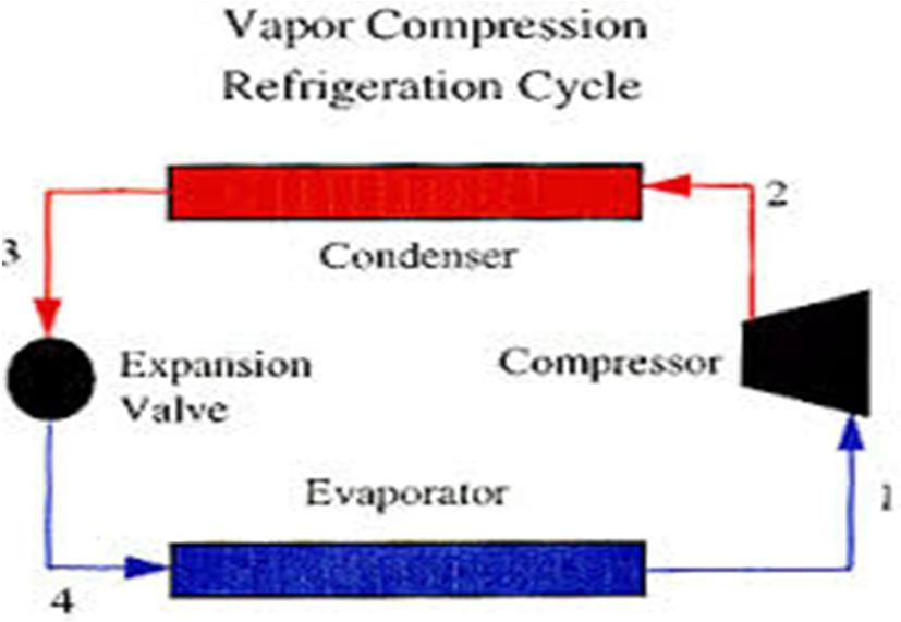

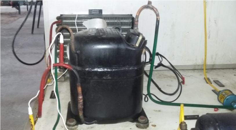
Fig.7: Evaporator
The liquid refrigerant from the condenser passed through the expansion device where it is throttled to lower pressure and at constant enthalpy. The liquid refrigerant is partly vaporized at lower tempafter throttling. The liquid refrigerant at pressure P3=P2 and temperature T3=T2 is expanded by a throttling process through the expansion valve to a low pressure P4=P1 and temperature T4=T1 as shown by the curve 3 4 on t s diagram and by the vertical line 3 4 on P H diagram. Some of the liquid refrigerant evaporates as it passes through the expansion valve, but the larger portion is vaporized in the evaporator. No heat is absorbed or rejected by the liquid refrigerant during the throttling process.
International Journal for Research in Applied Science & Engineering Technology (IJRASET) ISSN: 2321 9653; IC Value: 45.98; SJ Impact Factor: 7.538 Volume 10 Issue VIII Aug 2022 Available at www.ijraset.com 1742©IJRASET: All Rights are Reserved | SJ Impact Factor 7.538 | ISRA Journal Impact Factor 7.894 | Condensers are heat exchanger. Function of condenser is to get ride absorbed previously and reliquefy the refrigerant. The vapour refrigerant condenses a liquid at constant pressure.
Fig.6: Capillary Tube D. Evaporation In the evaporation the partly vaporized refrigerant completely evaporates at constant pressure by absorbing latent heat from the space. The liquid vapour mixture of the refrigerant at pressure P4 =P1 and temperature T4= T1is evaporated and changed into vapour refrigerant at constant pressure and temperature as shown by the horizontal line 4 1 on T s and p h diagram. During evaporation, the liquid vapour refrigerant absorbs its latent heat of vaporization from the medium (air, water or brine) which is to be cooled. The liquid refrigerant from expansion enters into evaporator coil at a temperature below the temperature of evaporator. It extracts heat from evaporator and coldness.
Fig.5: Condenser C. Expansion

Patil A.S. and Patil A.M. 2013 study on a “Selection of Capillary Tube for Refrigeration System”. This study aims to select a best capillary tube for a refrigeration system. The study is focused on the influence of geometrical parameters like tube length, diameter, and coil pitch, number of twist and twisted angle on pressure drop and coefficient of performance (COP) of the system. The parameters can be optimized using mathematical modeling, experimental methods and maintaining proper pressure between condenser and evaporator.
two temperature gauges
filled into the compressor.
International Journal for Research in Applied Science & Engineering Technology (IJRASET) ISSN: 2321 9653; IC Value: 45.98; SJ Impact Factor: 7.538 Volume 10 Issue VIII Aug 2022 Available at www.ijraset.com 1743©IJRASET: All Rights are Reserved | SJ Impact Factor 7.538 | ISRA Journal Impact Factor 7.894 | IV. LITERATURE REVIEW
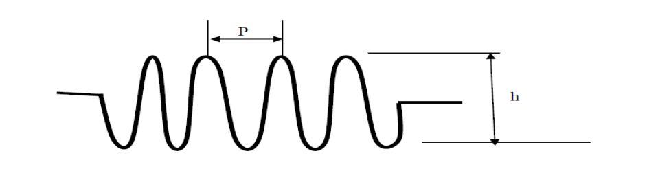
Salim T.K. 2012 studied that “The Effect of the Capillary Tube Coil Number on the Refrigeration System Performance”. The refrigerant is used in this experiment is (R134a) and capillary tube is straight and coil Capillary tube All properties of the refrigeration system are measured for various mass flow rate from (13 23 kg/hr) and capillary tube coil number (0 4) with constant length (150 cm) and capillary diameter (2.5mm).Through this study, it was found that the best coil number in refrigeration cycle at the lowest mass flow rate (31 Kg/hr) and at high mass flow rate (23 Kg/hr) is (coil number = 4), this will give the maximum performance, cooling capacity and deepest theoretical compression power. Akintunde M.A. 2008 investigated “The effects of various geometries of capillary tubes based on the coil diameters and lengths alone”. The effects of pitches of helical and serpentine coiled capillary tubes on the performance of a vapor compression refrigeration system were examined Some capillary tubes of equal lengths (2.03 m) and changing pitches, coiled diameters and serpentine elevations were used. The inlet and outlet pressure and temperature of the capillary tube were measured and used to estimate the COP of the system. The pitch has no significant effect on the system performancein the case of helical coiled geometries The COP obtained was 0.9841 in the case of serpentine geometries for mass flow rates of helical and serpentine with straight tubes, 0.9864 and 0.9996 for mass flow rates of serpentine and helical coiled tube respectively. This study examined the performance of capillary tube geometries having R 134a as the working fluid. EXPERIMENTAL SETUP
Soni et al. 2013 investigated the “Experimental Performance of Window Air Conditioner Using Alternative Refrigerants with Different Configurations of Capillary Tube”. R 22, R 410Awas the refrigerants used in this experiment and capillary tube was used in air conditioners with various refrigerants. Performance is carried out by using different type of capillary tubes (straight, twisted and coiled) in different length and diameter. Various parameters like coefficient of performance (COP), cooling capacity, energy efficiency ratio (EER) of the system were determined. If the diameter is smaller then the length is shorter and if the diameter is larger then length is longer and all these factors enable the exit pressure from the capillary tube to be reduced corresponding with the cooling requirements.
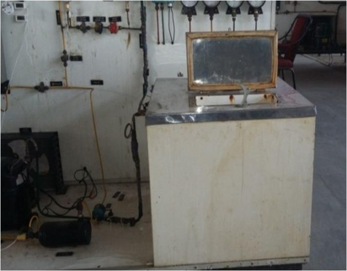
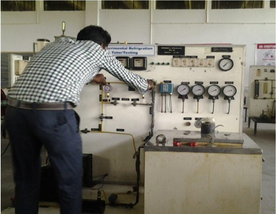
The experimental setup contains the compressor and valves that are shut off valves, rotameter by pass, expansion valve and tube expansion valve capillary. The control unit includes the main switch and measuring instruments like voltage, amp, meters, energy meters, pressure gauges, dial type thermometers and glass thermometers, pressure gauges.
The were installed in capillary tube line.After installation of pressure gauges, the 750 gm of refrigerant was
V.
Fig.8: Installation of Pressure Guages
International Journal for Research in Applied Science & Engineering Technology (IJRASET) ISSN: 2321 9653; IC Value: 45.98; SJ Impact Factor: 7.538 Volume 10 Issue VIII Aug 2022 Available at www.ijraset.com 1744©IJRASET: All Rights are Reserved | SJ Impact Factor 7.538 | ISRA Journal Impact Factor 7.894 | Fig 9: Installation of Refrigerant in Compressor A. Input Parameters Sr.No. MaterialCoilCapillary ShapeCapillary Refrigerant 01. tubeAluminum Serpentine R 22 02. tubeAluminum Cubic R 22 AlparticleNanowith 2O3 Nano Particle Aluminium Oxide (Al2O3) Purity 99.8% Particle Shape Spherical Particle size range 5 150 nm fromPurchased Reinste Nano Venture Pvt. Ltd. Table 1: Input Parameters B. Technical Specifications Pressure at compressor discharge 15 to 16 kgf/cm2 (220 psi guage) Pressure at compressor inlet 4.0 8to 5.08 kgf/cm2(60 psi guage) Temperature at compressor discharge 800 c Temperature at compressor inlet 220 c Temperature at condenser outlet 400 c Pressure at condenser outlet 16 kgf/cm2 Refrigerant flow rate (rotameter) 2.2 kg/min Table 2: Technical Specification
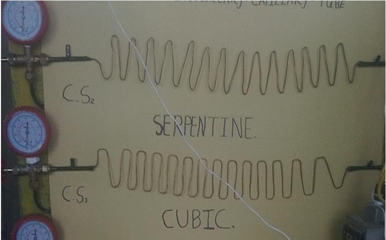
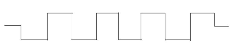
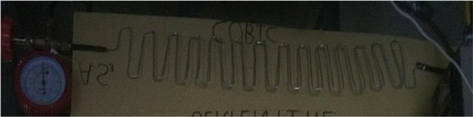
International Journal for Research in Applied Science & Engineering Technology (IJRASET) ISSN: 2321 9653; IC Value: 45.98; SJ Impact Factor: 7.538 Volume 10 Issue VIII Aug 2022 Available at www.ijraset.com 1745©IJRASET: All Rights are Reserved | SJ Impact Factor 7.538 | ISRA Journal Impact Factor 7.894 | VI. OBSERVATION AND CALCULATION AS 1=Aluminum Shape 1 (Serpentine) AS 2=AluminumShape 2 (Cubic) Observations for Refrigerant R22 eShap COMP.INLET DischargeComp. Cond. Outlet meterRota Expen. Before Expen.After TPTEM 1 0C PPRESS. 1 mKg/c 2 TTemp 2 0C PPress. 2 mKg/c 2 TpTem 3 0 C PPress 3 mkg/c 2 kg/min mKg/cPress 2 pTem 0 c mKg/cPress 2 pTem 0 c AS 1 30.9 2 57.2 11.5 33.3 11.9 0.4 10.2 32 1.2 20.8 AS2 31.2 2.1 71 11.7 34.7 11.8 0.4 10.5 32.2 1.5 20 Table 3: Observation Table for Capillary Tube For Nano particle Al2O3 with refrigerant R 22 eShap COMP.INLET DischargeComp. Cond. Outlet meterRota BeforeExpen. Expen.After TPTEM 1 0C PPRESS. 1 mKg/c 2 TpTem 2 0 C PPress. 2 mKg/c 2 TpTem 3 0 C PPress 3 mkg/c 2 kg/min mKg/cPress 2 pTem 0 c mKg/cPress 2 pTem 0 c AS 1 31.6 3 83.2 16.2 38.1 16.3 0.5 14.8 33.8 2.4 23 AS2 31.5 3.1 86.3 16.1 38.3 16.2 0.5 15.1 34 2.4 19 Table 4: Observation Table for Capillary Tube A. Coiled Capillary Tube Calculation Fig.10: Serpentine Coil Capillary Tube Fig.11: Cubic Coil Capillary Tube

International Journal for Research in Applied Science & Engineering Technology (IJRASET) ISSN: 2321 9653; IC Value: 45.98; SJ Impact Factor: 7.538 Volume 10 Issue VIII Aug 2022 Available at www.ijraset.com 1746©IJRASET: All Rights are Reserved | SJ Impact Factor 7.538 | ISRA Journal Impact Factor 7.894 | B. Co efficient of Performance (COP) Refrigerating Effect=h1 hf3 Compressor work done=h2 h1 Coefficient of Performance= Refrigerating Effect/ Compressor work done= h1 hf3/ h2 h1 h1 = Enthalpy of the refrigerant leaving the evaporator and incoming the compressor h2 =Enthalpy of the refrigerant leaving the compressor and incoming the condenser hf3=Enthalpy of the refrigerant leaving the condenser and incoming the expansion valve. For Refrigerant R 22 enthalpy table: No.Sr. h1 (kJ/kg) h2 (kJ/kg) hf3 (kJ/kg) (hnRefrigeratioEffect 2 h1) (horCompresswork 2 hf3) COP AS 1 235.65 260.11 76.04 24.46 159.61 6.53 AS 2 235.65 260.38 77.39 24.73 158.26 6.40 Table 5: Refrigerant R 22 For Refrigerant with Al2O3 Nano particle R 22 enthalpy table: NoSr.. (kJ/kg)h1 (kJ/kg)h2 (kJ/kg)hf3 h1)EffectRefrigeration(h2 hf3)WorkCompressor(h2 COP 1 243.25 263 95.63 19.75 147.62 7.47 2 243.25 263.13 97.03 19.88 146.22 7.36 Table 6: Refrigerant with Al2O3 Nano particle R 22 VII. RESULT TABLE FOR CAPILLARY TUBE Shape COP for R 22 COP for R 22 with Al2O3 Nano particle increasePercentage AS 1 6.53 7.47 14.395 AS 2 6.40 7.36 14.099 Table 7: Result Table for Capillary Tube Graph 1: Variation of Coefficient of Performance R 22 and Nano particle with R 22 VIII. RESULT ANALYSIS AND DISCUSSION
The measured parameters pressure (P) and temperature (T) was used to evaluate the coefficient of performance (COP). From the resultant values of the coefficient of performance and the graphical representation for the serpentine and cubic coiled capillary, it can be analyzed that with change in shape of the capillary tube the serpentine shape capillary tube gives better Coefficient of Performance than the cubic shape due to the resistance occurs in cubic shape is more comparatively. 5.5 6 6.5 7 7.5 8 1 2 Serpentine Cubic
International Journal for Research in Applied Science & Engineering Technology (IJRASET) ISSN: 2321 9653; IC Value: 45.98; SJ Impact Factor: 7.538 Volume 10 Issue VIII Aug 2022 Available at www.ijraset.com 1747©IJRASET: All Rights are Reserved | SJ Impact Factor 7.538 | ISRA Journal Impact Factor 7.894 | The Nano particle mixed with refrigerant enhances the thermal conductivity of the refrigerant and that by the rate of heat transfer increase and ultimately enhances the coefficient of performance of the refrigeration system. IX. CONCLUSION
4) Nano particle Al2O3 enhances the refrigerating effect by R 22 by around 15% in case of serpentine shape capillary tube.
2) Cubic shape capillary tube offers more resistance to flow of refrigerant, so its pressure reduction is less comparatively.
3) Refrigerant having mixed Al2O3 Nano particle with R 22 gives better Coefficient of performance of the refrigeration system. This is happens because the thermal conductivity property of Al2O3 Nano particle is high which increase the conductivity rate of refrigerant and ultimately enhances the COP.
1) AS 1 i.e. Serpentine shape capillary tube provides better flow of the refrigerant due to less resistance in flow and enhances the Coefficient of Performance of the refrigeration system.
REFERENCES
[1] SONI, R. (2013) Experimental Performance of Window Air Conditioner Using Alternative Refrigerants with Different Configurations of Capillary Tube. International Journal of Engineering Sciences & Research Technology. [2] PATIL, A.S. and PATIL, A.M. (2013) Selection of Capillary Tube for Refrigeration System. International Journal of Engineering Inventions, 2, pp. 52 55. [3] WANKHEDE, U.S. (2012) Selection of spiral capillary tube for refrigeration appliances. International Journal of Modern Engineering Research, 2(3), pp. 1430 1434 [4] SALIM, K.TAMIR (2012) The Effect of the Capillary Tube Coil Number on the Refrigeration System Performance. Tikrit Journal of Engineering Sciences, 19.. [5] TARRAD, A.H (2008) A Numerical Analysis of Adiabatic Capillary Tube Performance in Vapor Compression Refrigeration Systems. The Iraqi Journal For Mechanical And Material Engineering,8.
This study investigated the coefficient of performance of refrigeration system on the basis of capillary tube shapes having R 22 as the working fluid. It reaches the following conclusion: