https://doi.org/10.22214/ijraset.2023.48629

11 II
February 2023
ISSN: 2321-9653; IC Value: 45.98; SJ Impact Factor: 7.538
Volume 11 Issue II Feb 2023- Available at www.ijraset.com

https://doi.org/10.22214/ijraset.2023.48629
ISSN: 2321-9653; IC Value: 45.98; SJ Impact Factor: 7.538
Volume 11 Issue II Feb 2023- Available at www.ijraset.com

Abstract: This paper proposed the development of an tethered Drone to be used for application. Drones become essential for various application. The main drawback of the drones is that the time of flight is very less (around 20 minutes).The proposed system aims to provide continuous power supply to the drone by using power supply from ground. The twisting and tangling of wires is another problem, so we have provided a slip ring mechanism to avoid twisting of cable. In this system author used IMU 6DOF (3-axis accelerometer& 3-axis gyroscope) which ensure it smooth movement, graceful motion and trajectory tracing. GPS system and barometric sensor makes it more efficient in autonomous mode. UAVs have limited operational autonomy, determined by their on-board available power. An autonomous power tethered UAV-UGV team couples those two classes through a power linkage. This serves to increase the UAV’s autonomy in terms of flight time, while concurrently the aerial platform’s utility as an eye-in-the-sky can provide the UGV with increased knowledge of its surroundings. Finally, this physical constraint can grant additional benefits at aerial vehicle control level, especially under the potential presence of strong wind gusts. The developed autonomous operation strategy is examined within a simulated scenario with limited prior map knowledge, which includes a number of unmapped challenges.
At present world drone technology is extremely acquainted & versatile technology. Drone will drift in air. We will conjointly use wireless camera with it. So we will use it to try and do differing types of tasks. Nowadays Drones are used in long mile wars as a weapon and also as a helper of fighter in the war. Drone are used by scientist as a part of their research assistant. Drones not only help us in society but also a threat for us, as because many of developed countries use it as their weapon of destruction. So drones have their ability to predetermined work so that it becomes important in today’s world. At past drones was used only by military in their war. But day by day it is now used in various household works as it operation and control become easy day by day. Developed world and also developing world use it for their own purposes. Uses of drone are rapidly increased for both public & Private sector. Peoples of Canada & North America now use drone as their assistant of housework & office work. At present not only in Canada but also in others countries drone technology increasing day by day. For the domestic user they have to pay attention on government rules regarding use of drone. For this propose small & cost effectives drones are available in markets. Its popularity increased day by day. So for this issue many governments declared some rules and regulation to fly drone in different purposes. A mature quad rotor system can use for educational and experimental porpoise. Photo shoot for films & drama are also use drone.

To design a stable multi copter we need maintain some physics, mathematics and aerodynamic term. Aerodynamic help to define its movement and inertial motion. In the other hand mathematical calculation helps to manipulate required lift force, angular position, graceful motion and trajectory definition. We designed drone’s body according with dynamics and also designed artificial algorithm to make it autonomous and well behaved. Hardwire system consists of different sensors, powerful controller unit and electronic equipments so on. For a desire movement controller takes data from different sensors. 3-axis accelerometer and 3-axis gyroscope provide data of itsorientation, acceleration and angular rate. Then these data processed and compare with reference and desire value. This operation performs with the help of PID loop. Several PID loops used in these case like pitch control, roll control, yaw control, hover, altitude holding and orientation control. IMU (inertial measurement unit) provides real altitude, angular movement and orientation. After that required pulse sends to ESC (Electronic Speed Controller) for desire speed of rotation. Magnetometer provides real time direction with the global magnetic field reference. Barometric pressure sensor also provides real time altitude. GPS (global position system) module helps to make system autonomy. It helps find out any coordinate and reach to this coordinate. Telemetry kit helps to observe flight data wirelessly from ground station. It also send mission file and communicate with air part like USB serial mode (TTL mode).
In ground part consists of powerful ground station. PC/Laptop used for sending data through telemetry and coding or data logging from air part. Another radio transmitter used to switch different mode and operate in manual mode.
ISSN: 2321-9653; IC Value: 45.98; SJ Impact Factor: 7.538


Volume 11 Issue II Feb 2023- Available at www.ijraset.com
The material which is used to build the drone is glass-fibre which is high rigid and well adapted to withstand the sudden impact on it. The Landing gear is made up of PVC plastic with a tendency of arresting sudden impact on it. The circuit which integrated with the frame consist of silicone layer which helps to manipulate the integrated circuit.

ISSN: 2321-9653; IC Value: 45.98; SJ Impact Factor: 7.538
Volume 11 Issue II Feb 2023- Available at www.ijraset.com
To design a stable multi-rotor copter we have to concentrate its structure and dynamics. We have to develop a firmware in which contains different control strategy, mode of operation, data evaluation and different PID loops for stability.
The thrust T produced by each motor is calculated as
T= ρCT A wm 2 R2
Where
CT : thrust coefficient
ρ: Air density
A: rotor disk area
R:blade radus
Propeller diameter& pitch –D ~ τ , p ~ τ
τ ~ E
Where, D: diameter of propeller,
τ: Torque,
E: Energy
Frame parameters-
Blade tip speed, v~sqrt(R)
Lift, F ~ R3
Inertia, m ~ R3 , I ~ R5
Acceleration, linear a~ 1 , angular a ~1/R
Where, R: frame centre to motor distance
The dynamics of DC motor is generally described as
Li (di/dt) + Ri+kc wm = u
J (dWm/dt) = τ – τd
Where
Li: Coefficient of inductance
i: armature current
R: armature resistance
Ke: back emf constant
wm: speed of motor
u: armature voltage
J: inertia of motor
PID (proportional-integral-derivative) is a closed-loop control system. It helps to get c our results as must as close to the actual result by responding to our inputs. Scientist uses it while controlling drone or robot for achieves stability.
ISSN: 2321-9653; IC Value: 45.98; SJ Impact Factor: 7.538


Volume 11 Issue II Feb 2023- Available at www.ijraset.com
PID basically works with three algorithms.
P depends on the present result
I on the accumulation of past errors.
D is prediction of future errors based on current data.
Different coding systems are available based on these Algorithms[7]. Per axis PID structure shown in Fig.9. For controlling hexacopter or any types of multi copters, output of sensors (like the pitch angel) is very much needed. From the sensor data we can easily estimate the error (how far we are from the desired pitch angle, e.g. horizontal, 0 degree). Then we can use PID algorithms for eliminating errors
ISSN: 2321-9653; IC Value: 45.98; SJ Impact Factor: 7.538
Volume 11 Issue II Feb 2023- Available at www.ijraset.com
For steady level flight in drone:
T= W0
T= 22.07 N
By George rule:
2*Trequired = Tavailable
Tavailable = 44.145 N
The proposal system must have capable of lifting 4.5 Kg.
Tavailable =4.5 Kg Hexacopter consist of 6 arm propulsion system.
1) Iteration 1 (1000KV BLDC motor + 9*4.5 Propeller)
Theoretical value Toutput = 0.506 kg = 4.9638 N force
Tmax = 29.78316 N , lift weight capacity : 3.036 kg
Tmax < Tavailable
Therefore the proposed system does not meet the requirement condition.
2) Iteration 2 (1000 KV BLDC motor + 10* 4.5 Propeller)
Theoretical Value Toutput = 0.750 kg = 7.3575 N
Total Thrust generated
Tmax = 6* 7.3575 = 44.145 N
Tmax can lift up to 4.5 kg
Tavailable = Tmax
The proposedpropulsion system is found to be sufficient.
A. Description
This Section presents the complete system setup used for the scope of this paper.

With reference to the mark up of Figure 5, the PoT’s main component is the Winder Drum a), upon the central perimeter of which the power cable is wound. The Winder Drum is attached on one side on a Ball bearing joint, thus rotating w.r.t the PoT base around the indicated b) Degree of- Freedom (DoF)-1. Measurement of the Winder Drum’s rotations is enacted with the help of 2 parallel placed latching-action Hall-effect Sensors -marked as Encoder 1. which sense the presence of small Neodymium Magnets placed onto the perimeter of the Winder-to-Ball bearing support shaft. The Magnets array consists of 2 pairs of 20 magnets, interchangeably placed in each series (w.r.t. each sensor) such that their outward-pointed poles-sequence is North-South-North-etc.
ISSN: 2321-9653; IC Value: 45.98; SJ Impact Factor: 7.538
Volume 11 Issue II Feb 2023- Available at www.ijraset.com
Moreover, the 2 series of the array are radically spaced in-between each others’ empty spaces, such that the Hall-effect Sensors can encode the direction of rotation. Also, it is noted that the cable is inserted into the Winder Drum at a hole, and exits from the support shaft at location d). As can be observed, Cable Exit d) supports the cable’s two phases in parallel placement, hence any twisting occurs from d) and up to the external power source. Mapping between the Free Cable Length L and the Winder Drum absolute turns can be estimated given the dimensioning of the respective elements; however, for a total cable length of 8 m and the Winder dimensioning in this implementation, it can be approximated via 2-nd order polynomial fitting of experimentally-derived values, yielding a relation:
L ≃Lpol = aL 2+ bL + cL (1)
In the proposed implementation, there is an additional Degree-of-Freedom -marked as DoF-2 in e) -, which exists due to the fact that the f ) Servo’s shaft can rotate w.r.t. its body, which is attached onto a Ball bearing joint in e). For a locked servo shaft, DoF-1 and 2 rotate coincidentally, otherwise relative rotation is possible. The Servo is also attached onto the rigid Pot base body via a RetainerSpring g). This allows DoF-2 to rotate, but more importantly it returns the Servo and DoF-2 back to an original rotation, when the Spring contracts (following elongation which is caused by an externally applied pulling force. The Rotary Encoder 2 in h), implemented with a potentiometer measures the absolute deviation of DoF-2 from its original rotation (at zero Spring elongation), and is used to estimate the Spring’s elongation. Additionally to the Retainer-Spring g), the servo rotation is limited up to an approximate maximum of 60 deg via a non-elastic retainer. This prohibits any non-elastic (catastrophic) elongation of the Spring, but more importantly it allows “locking” of DoF-2 and enables passing the full torque of the Servo onto the Winder DoF-1 (as no additional elongation of the Spring is possible). The aforementioned implementation aims to achieve local “sensing” of the UAV’s tendency to distance itself from the Pot base, or backtrack towards it: when the aerial vehicle moves away it pulls against the cable, and the mechanical tension force is transferred via the Winder Drum onto DoF-2, effectively elongating the Retainer-Spring. When the opposite manoeuvre happens, mechanical tension is decreased and the Spring is compressed accordingly. This principle is used to achieve force-feedback estimation and control the PoT system via the actuation principle granted by the Servo; the specific control synthesis is elaborated in Section III. The PoT base can also rotate w.r.t. to the World-frame X, as marked by DoF-3 in i). A Ball bearing joint and a fixed-base shaft guarantee minimal friction, while the absolute Rotary Encoder 3 j) -also a potentiometeryields the respective measurements. It is noted that due to the potentiometer the rotation range of DoF-3 is constrained in [ 120, 120] deg. A short-range infrared distance sensor marked as k) is used to measure the height of the cable at the exit point of the PoT base. It is placed at a low point to allow certain vertical distance from the cable exit, as its measurements are unreliable below a threshold of ≃0.040 m. The functionality of this implementation is further discussed in Section III. An additional component of crucial operating significance is the Flex Sensor marked as l), properly placed at the PoT base ground-to-air cable exit at a height which is marginally higher than the reliability threshold of the Distance Sensor k). This serves to detect cable contact which occurs before the too-short range limit of the Distance Sensor, which might also signify that due to excessive slacking, part of the cable is in contact with (has fallen onto) the ground. This is a particularly undesired occasion which can cause operational problems, as will be discussed in Section III. Finally, an onboard Microcontroller m), the DF-Robot Mega2560 specifically, is attached onto the PoT base. This handles the acquisition of measurements from the onboard sensors, the estimation of all necessary values, and the computation of the necessary control actions. It is also responsible for the generation of the low-level control signals which are required to drive the Servo actuator. It is additionally noted that a Qt-based Graphic User Interface tool has been developed in order to visually display the PoT’s operating values -acquired from the Microcontroller’s serial port- and to override its autonomous control process in real-time operation, and to log all necessary operational values for post-processing.
As previously described, in order to maintain operational safety, it is important for the PoT system to be capable of functioning autonomously. The capacity to “sense” the UAV’s tendency to move at a greater distance or to backtrack, as well as the approximate estimation of their relative position vector orientation -assuming no physical interaction occurs between the PoT ground base and the vehicle in the air-, is achieved locally, as described within Section II-A. Let the PoT locally measured values be defined as: a) is the number of rotations of the winder, which is directly measurable by the hall-effect sensor array. b) L is the tethering line (free cable) length, starting from the winder drum and ending at the UAV, which is estimated as described in Section III-A. c) T is the tension force on the cable, transferred to the outer radius of the winder and estimated via the measurement of the retainer spring’s elongation according to Hooke’s law. It is noted that a “soft” sensitive spring is used in order to acquire small deviations via a simple measuring device (a rotary potentiometer at DoF-2). d) marks the servo’s rotational speed (i.e. rotations/sec).
ISSN: 2321-9653; IC Value: 45.98; SJ Impact Factor: 7.538
Volume 11 Issue II Feb 2023- Available at www.ijraset.com
The continuous rotation servo acts as a slow-rotating DC motor, and is used to control DoF-1 by modifying according to a free cable length reference Lr , and thus releasing/retracting the cable. It assumed that r ≃ , i.e. the commanded rotational speed is the actual one (where the r superscript marks the reference value). e) zc is the cable suspension height as measured by the distance sensor, w.r.t. the winder drum’s outer perimeter height. f) F is the flex sensor state. This is treated as a Boolean value, i.e. either there exists physical contact of the cable and the sensor, or not. Finally, g) PoT is the orientation of the PoT Frame w.r.t. Worldframe X as measured by the DoF-3 rotary encoder.
The PoT control synthesis follows the cascaded control structure paradigm, as illustrated in Figure 6. The employed control principles are as follows:
This section of the control structure is considered as the inner loop of the cascaded scheme. It is driven by a reference absolute free tethering-line length Lr which is converted to a respective winder-turns value r based on (1), and computes the servo rotational speed command r, based on the relation:
(3)
(4)
Reflecting a Proportional control logic which manipulates the rate of release/retraction of the cable (tethering link). Defining as positive the direction of rotation which releases the cable (and negative the one which retracts it), it is noted that the maximum and minimum rates that can be achieved are constrained in ∈[ el , mech], where el the servo’s maximum controlled speed, and mech the servo’s maximum speed under a large externally applied additive rotating moment, which does not cause it to suffer catastrophic failure.
Essentially, this means that while retracting the cable, the maximum rate is determined by the servo’s operational characteristics, while when the cable is released, the rate of rotation can be further accelerated if the UAV is also pulling it. Also, it is noted that (3),(4) yields a control action which is fed to an integrating system (the servo which rotates until reaches r), i.e. the Proportional authority controls the rate of integration.

This is the next level of the cascaded control structure block. It is responsible for the generation of an appropriate Lr reference signal, according to the desired principle of operation. For the purposes of this work, the key requirement is to maintain the tethering link (the cable) at a specific tension, encoded via a reference value Tr . In proper operation, the PoT mechanism will release additional cable length when it “senses” that the UAV is pulling away, and retract it in case it becomes excessive, e.g. when thUAV returns to close its distance from the PoT ground base. This “sensing” is achieved locally via estimation of T as preciously elaborated. The specific methodology falls along the lines of an Integrator-control logic, with two operating regions encoded by an auxiliary logical variable s ∈[Retract, Release], as illustrated in Figure 6.
Lr = KL s ∫ T dt (5)
e T = Tr – T (6)
KL = KL Release’ IF s= Release
KL Release’ IF s= Retract (7)
ISSN: 2321-9653; IC Value: 45.98; SJ Impact Factor: 7.538
Volume 11 Issue II Feb 2023- Available at www.ijraset.com
S: Release,
r Retract, IF s <= Tr (8)
Lr → L, IF Release ↔Retract where {KLRelease, KLRetract} are different gains with the utility of achieving equally-scaled releasing and retraction actions (due to the mechanical aiding of releasing when a UAV pulling force is active on the tethering line, as discussed in Section III-A). It is noted that when a switching of the logical variable s occurs according to rule-set (8), the reference Lr value is reset to L, in order to avoid delaying the system’s response due to error integration/control action windup. This is necessary as the aerial vehicle side may perform quick pulling away/returning motions which require an equally quick response on the PoT system-side. It is finally mentioned that the Integral-logic control of (5),(6) generates an increasing (/decreasing) Lr reference value as the UAV pulls away from (/returns back to) the PoT ground position respectively, and the rate of increase (/decrease) depends on the magnitude of the applied tension -e.g. how strongly the aerial vehicle pulls.
A Brushless Dc electric motor (BLDC motor), also known as electronically commutated motor(ECM motor),and synchronous DC motors, are synchronous motors powered by direct current(DC) electricity via an inverter od switching power supply which produces electricity in the form of alternating current (AC) to drive each phase of the motor via a closed loop controller. The controller provides pulse of current to the motor winding that control the speed and torque of the motor. The main advantages of brushless motor over brushed motor are high power to weight ratio, high speed electronic control, and low maintenance.
Here we use 1000 kv motor which can run at speed of 11100 rpm. It drawn current 10 amp from source.
An electronic speed controller (ESC) is an electronic circuit that acts as the interface between the pilot’s commands and the individual drone motor. But brushless motors require a 3 phase ESC.


ISSN: 2321-9653; IC Value: 45.98; SJ Impact Factor: 7.538
Volume 11 Issue II Feb 2023- Available at www.ijraset.com
We have used single shot regular ESC with capactity of 30 A

• Esc of 30 A
• Output:30Acontinuous
• Short power: 40amp for 10s
• Function voltage:7.4 to 14.8v
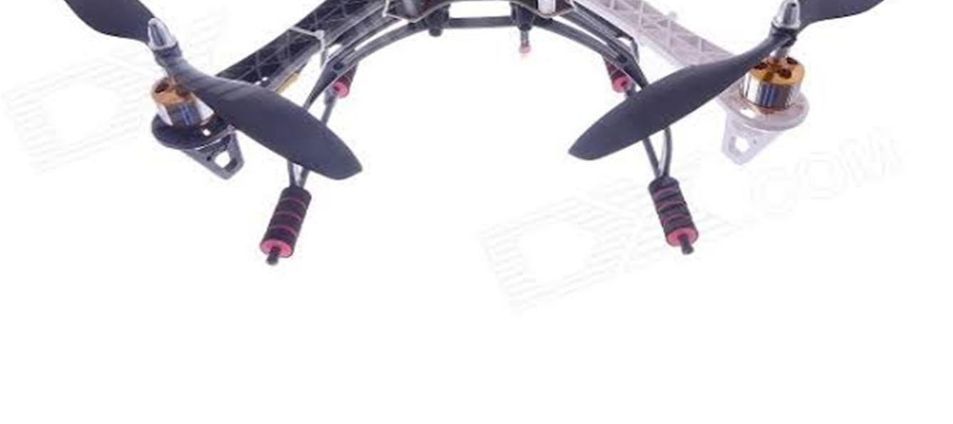
The Propeller which act as a thrust producing device which rotates by mounting on the motor and generates lift which propel the hexacopter in the air.
The propeller which used to develop tethered drone is 10*4.5 plastic propeller.

The flight controller is the brain controller for the whole system which is used in the tethered system. The flight controller need to be more realistic and predominant in controlling the system.This has many sub connected mini supporting which gives high stability.
This system consist of pixhawk 2.4.8 32 bit flight controller which gives high stability with Gps system.

As per the Indian standard Average building height 15 m.
If the tethered system is escalated above the 15 m won’t have any obstacle to hit by the tethering technology. Telescopic Tower with retractable tower helps to elevate the wire above the range of obstacle so that it can fly freely in unbounded sky.
ISSN: 2321-9653; IC Value: 45.98; SJ Impact Factor: 7.538
Volume 11 Issue II Feb 2023- Available at www.ijraset.com
This tower would be in stages which will expanded to the required height suitable for the zone of flight. Thus it can be easily move from one stop to other.
A Power-over-Tether system for remote powering of small-scale Unmanned Aerial Vehicles was proposed. The system was designed and implemented at the device level, with all components elaborated and presented w.r.t. their operating principles. The necessary control synthesis, in order to achieve the required level of communication-independent functionality, was presented and thoroughly analyzed. Together with a high-end hexa rotor platform, the operational capacity of the PoT system was evaluated in a set of experimental evaluation studies. The demonstrating the proposed system’s potential for use within realistic applications.
[1] Papachristos, K. Alexis, and A. Tzes, “Technical activities execution with a tiltrotor uas employing explicit model predictive control,” in International Federation of Automatic Control, Proceedings of the 19th IFAC World Congress, Cape Town, South Africa, 2014, p. to appear.
[2] K. Alexis, C. Huerzeler, and R. Siegwart, “Hybrid modeling and control of a coaxial unmanned rotorcraft interacting with its environment through contact,” in 2013 International Conference on Robotics and Automation (ICRA), Karlsruhe, Germany, 2013, pp. 5397–5404.
[3] C. Papachristos, K. Alexis, and A. Tzes, “Efficient force exertion for aerial robotic manipulation: Exploiting the thrust-vectoring authority of a tri-tiltrotor uav,” in 2014 International Conference on Robotics and Automation, Hong Kong, China, 2014, p. to appear.
[4] L. Cantelli, M. Presti, M. Mangiameli, C. Melita, and G. G. Muscato, “Autonomous cooperation between uav and ugv to improve navigation and environmental monitoring in rough environments,” in Proceedings 10th International symposium HUDEM,(ISSN 1848-9206), 2013, pp. 109–112.
[5] G. Tanner, “Switched uav-ugv cooperation scheme for target detection,” in Robotics and Automation, 2007 IEEE International Conference on. IEEE, 2007, pp. 3457–3462.
[6] “A marsupial surface-aerial robotic team for riverine environmental monitoring (riverwatch).” [Online]. Available: http://riverwatchws.cloudapp.net/
[7] S. Lupashin and R. D’Andrea, “Stabilization of a flying vehicle on a taut tether using inertial sensing,” in Intelligent Robots and Systems (IROS), 2013 IEEE/RSJ International Conference on, Nov 2013, pp. 2432–2438.
[8] S. Karaman and E. Frazzoli, “Incremental sampling-based algorithms for optimal motion planning,” arXiv preprint arXiv:1005.0416, 2010.
[9] C. Papachristos, K. Alexis and A. Tzes, ”Technical Activities Execution with a TiltRotor UAS employing Explicit Model Predictive Control,” in Proceedings of the 19th IFAC World Congress of the International Federation of Automatic Control, 2014.
[10] C. Papachristos, K. Alexis and A. Tzes, ”Efficient force exertion for aerial robotic manipulation: Exploiting the thrust-vectoring authority of a tri-tiltrotor UAV,” in IEEE International Conference on Robotics and Automation (ICRA), 2014.
[11] L. A. Sandino, M. Bejar, K. Kondak, and A. Ollero, ”Advances in modeling and control of tethered unmanned helicopters to enhance hovering performance,” Journal of Intelligent & Robotic Systems, vol. 73, no. 1–4, pp. 3–18, 2014.