2 minute read
International Journal for Research in Applied Science & Engineering Technology (IJRASET)


ISSN: 2321-9653; IC Value: 45.98; SJ Impact Factor: 7.538
Advertisement
Volume 11 Issue II Feb 2023- Available at www.ijraset.com
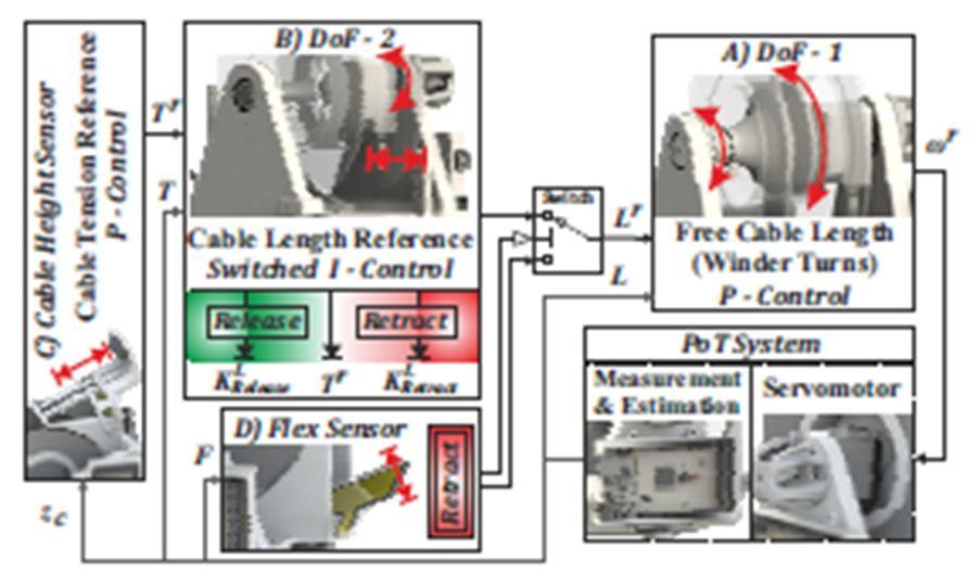
The continuous rotation servo acts as a slow-rotating DC motor, and is used to control DoF-1 by modifying according to a free cable length reference Lr , and thus releasing/retracting the cable. It assumed that r ≃ , i.e. the commanded rotational speed is the actual one (where the r superscript marks the reference value). e) zc is the cable suspension height as measured by the distance sensor, w.r.t. the winder drum’s outer perimeter height. f) F is the flex sensor state. This is treated as a Boolean value, i.e. either there exists physical contact of the cable and the sensor, or not. Finally, g) PoT is the orientation of the PoT Frame w.r.t. Worldframe X as measured by the DoF-3 rotary encoder.
The PoT control synthesis follows the cascaded control structure paradigm, as illustrated in Figure 6. The employed control principles are as follows:
A. Cable L Free Length Control – Winder Turns Control
This section of the control structure is considered as the inner loop of the cascaded scheme. It is driven by a reference absolute free tethering-line length Lr which is converted to a respective winder-turns value r based on (1), and computes the servo rotational speed command r, based on the relation:
(3)
(4)
Reflecting a Proportional control logic which manipulates the rate of release/retraction of the cable (tethering link). Defining as positive the direction of rotation which releases the cable (and negative the one which retracts it), it is noted that the maximum and minimum rates that can be achieved are constrained in ∈[ el , mech], where el the servo’s maximum controlled speed, and mech the servo’s maximum speed under a large externally applied additive rotating moment, which does not cause it to suffer catastrophic failure.
Essentially, this means that while retracting the cable, the maximum rate is determined by the servo’s operational characteristics, while when the cable is released, the rate of rotation can be further accelerated if the UAV is also pulling it. Also, it is noted that (3),(4) yields a control action which is fed to an integrating system (the servo which rotates until reaches r), i.e. the Proportional authority controls the rate of integration.
B. Tether T Tension Control – Cable Lr Free Length Reference Generation
This is the next level of the cascaded control structure block. It is responsible for the generation of an appropriate Lr reference signal, according to the desired principle of operation. For the purposes of this work, the key requirement is to maintain the tethering link (the cable) at a specific tension, encoded via a reference value Tr . In proper operation, the PoT mechanism will release additional cable length when it “senses” that the UAV is pulling away, and retract it in case it becomes excessive, e.g. when thUAV returns to close its distance from the PoT ground base. This “sensing” is achieved locally via estimation of T as preciously elaborated. The specific methodology falls along the lines of an Integrator-control logic, with two operating regions encoded by an auxiliary logical variable s ∈[Retract, Release], as illustrated in Figure 6.
Lr = KL s ∫ T dt (5) e T = Tr – T (6)
KL = KL Release’ IF s= Release
KL Release’ IF s= Retract (7)


