10 XII December 2022 https://doi.org/10.22214/ijraset.2022.48231
ISSN: 2321-9653; IC Value: 45.98; SJ Impact Factor: 7.538 Volume 10 Issue XII Dec 2022- Available at www.ijraset.com


ISSN: 2321-9653; IC Value: 45.98; SJ Impact Factor: 7.538 Volume 10 Issue XII Dec 2022- Available at www.ijraset.com
Abstract: Human Powered Water Purifier is the system which provides safe drinking water by running a RO systemwith the help of only human power and minimal setup.This can prove to be a major cost effective solution tothe problem of unsafe drinking water in areas where there is no or little access to modern purifiers or they do not have the power source to run them ( either irregular electricity supply or in emergency situations). This paper explains in detail about the design of an indigenous mechanism which makes useof human pedalling on a bicycle & power istransmitted by sprocket and belt pulley system toobtain required RPM for pump to run a water purification system. It includes a brief picture of the need of this type of system, design of various components and the summary of results obtained during the testing of the system. This mechanism has shown positive results in maintaining the pressure andflow Rate from pump by providing about 1200 RPM with mechanism, required by RO Purifier and TDS (Total Dissolved Solids) in water was considerably reduced from 650 ppm to 150 ppm.
Keywords: Purifier, Reverse Osmosis (RO), Total Dissolved Solids (TDS), Revolutions per Minute (RPM), Human Power, Sprocket, Belt – pulley.
Today most of the water sources are not safe fordrinking due to heavy industrial and environmental pollution. According to a UN Report in 2013 nearly 2000 children around the globe under the age of five die every day from diarrheal diseases linked to unsafe water with 24% of deaths in India alone. So there is much need for effective as well as viable water purification methods. Such methods and related techniques have been in existence since ancient times and with advancement in science and technology techniques have become quite efficient and effective. However these modern water purification methods are beyond reach of backward areas due to lack ofresources, awareness, electricity and reluctance to usehigh technology products. In many parts of India thereis no regular electricity supply which makes it almostimpossible to use these water purifiers even if peopledecide to use it. The solution to this problem can be given by replacingthe external power source required to run the purifier by independent, effective and easily available source that is Human Power. In this project Human Power isharnessed by an indigenous mechanism to run a RO water Purification system. The mechanism incorporates simple mechanismofsprocket and pulleyto obtain required rpm of pump shaft of RO. The efficient Design and Fabrication of this system forms the fundamental objective of this paper and its successful implementation can pave way for using human power for a variety other applications also. Some of the main features which we wish to incorporate in this project are
1) Efficient purification of water
2) No use of external except Human Power
3) Minimal setup
4) Low cost of maintenance and installation

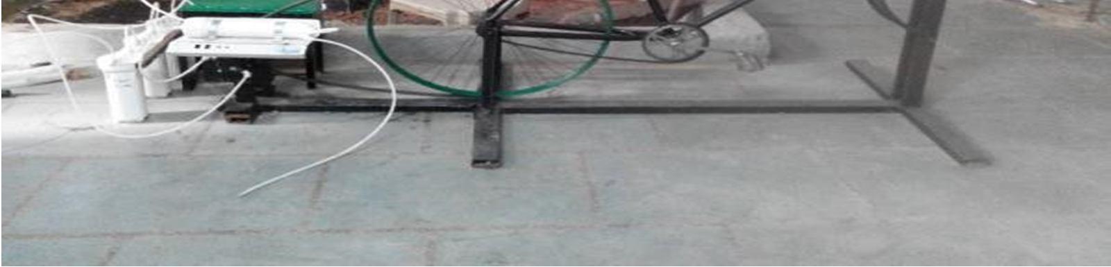
The basic idea of design is quite simple. A common bicycle is used for pedaling and the RPM of pedaling is transmitted via chainsprocket and belt-pulley mechanism to get increased RPM at the pump shaft inthe end of mechanism. The pump is then used to drive a RO system by supplying pressurized water so that which we can get purified water. Various components of the system are designed by keeping in mind few considerations making them suitable for this application
The main power source of our project is the power produced by pedaling which can be used to drive the pump shaft at the rear end. A common bicycle was thebest option available for us as it is both easily available and cheap, both factors being crucial to the overall project. We used a bicycle of Hercules Company, which is quite stable and stronger than most of commercial cycles available in the market, commonlyused by Adults or may be by children. To suit our need, we removed the wheels of the bicycle as it has to be mounted over the frame.
ISSN: 2321-9653; IC Value: 45.98; SJ Impact Factor: 7.538 Volume 10 Issue XII Dec 2022- Available at www.ijraset.com
The next important part of the structure is the foundation on which the cycle will be mounted and themechanism incorporated at the rear side of frame. We had two options available for the material to be used, wooden blocks and Rectangular hollow steel sections. Following factors are considered for selection of steel sections:
1) Ease of Availability: Thehollowrectangularsections of steel were easily available in the form of scrap steel.
2) Strength: As the whole setup needs to support a weight of almost 120 Kg (cycle weight + human weight), the steel section was the most suitable option of the two for stabilityand security.
3) Ease of Fabrication: The fabrication process required anumber ofjointsandholesto be made. Such operations on wood were both time consuming and had a risk of wear with time. On other hand, they can be performed easily on steel by drilling and welding operations.
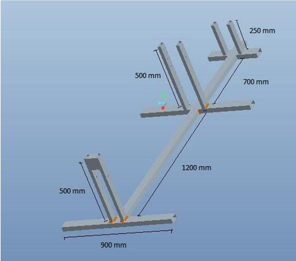
The structural frame is designed in Pro-E wildfire 5.0to initiate the fabrication work. This has two I – Sections and vertical supports. The vertical supports for supporting the bicycle and rear vertical supports are for supporting pump heads and pulley shaft arrangement.
a) Material: IS 4923:1997 (Rectangular HollowSteel Section)
b) Dimensions: Cross section- (66×33×2.9) mm &Length- 5400 mm Cross section- (50×25×1.5) mm
The rear mechanism referred to the power transmission from front sprocket to rear sprocket and from there it transmitted to the pump. It containsfollowing:
The power from front sprocket is transferred to the rear sprocket using a chain drive using a bicycle chain as itis an inexpensive, easy-to-install and highly efficient drive mechanism. There can be two types of bicycle chains which can be used: Single speed and multi- speed.
Single speed chain is mainly used on kids' bikes, BMX bikes, coaster brake cruisers, and heavy cargo bikes. Multi-speed chain is used on standard speed bikes andmountain bikes that arerequired to change gears. Bothtypes of bicycle chain have a pitch of ½ inch (ANSI standard #40).
We have used the single speed chain used in commonbicycles, reference code: (1/2×1/8) inch.
ISSN: 2321-9653; IC Value: 45.98; SJ Impact Factor: 7.538
Volume 10 Issue XII Dec 2022- Available at www.ijraset.com
Therear sprocket carries the bicycle rear wheel whichacts as the bigger pulley of belt pulley system.
a) Bigger pulley diameter (Bicycle wheel):675 mm
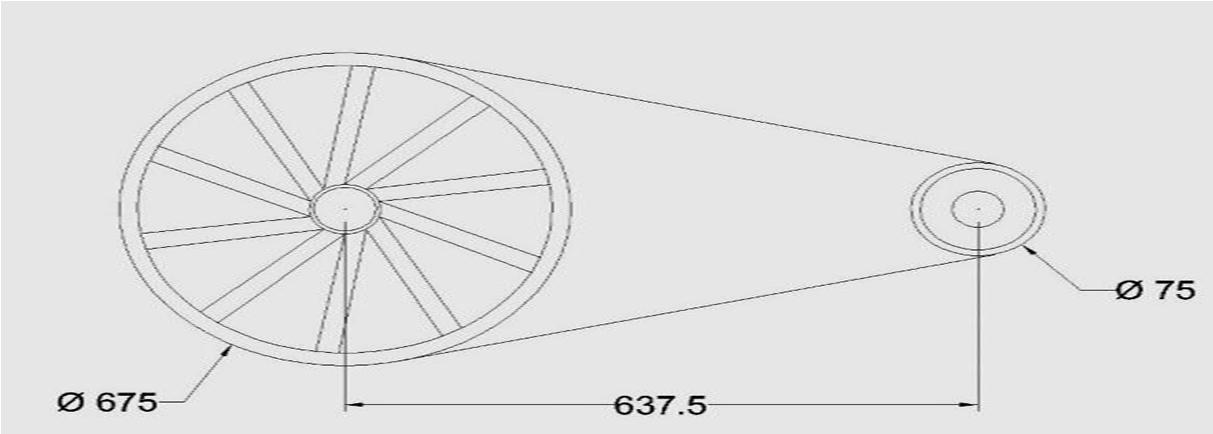
b) Smaller Pulley diameter: 75 mm
c) Centre distance between pulleys: 637.5mm
A V-Belt is used to transmit power between twopulleys. The specification of V-Belt is: Emcom B-100
Length of Belt: 2500 mm (100 inches)
Figure 2: Belt Pulleyarrangement
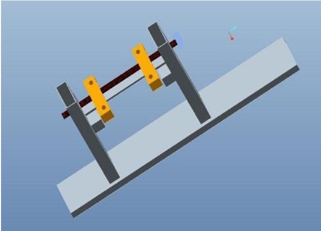
3) Shaft: Shaft is the component which transmits power fromrear pulleyto drive the pump. Material: Mild steel Diameter: 12 mm Length: 335 mm
The shaft is step-turned to 8 mmdiameters at sprocketand pump side both.
4) Bearings: Bearings are used of NBC bearings. The specificationfor bearings were Model: 6001ZZID: 12 mm OD: 28 mm
These bearings are fixed on the shaft by fitting thebearing inner case on shaft with tolerance
Tosupport thebearings and make themaligned pillowblocks are fabricated using wooden blocks of following dimensions: Wooden block cross section: (37.5 × 18.75) mmLength of block: 150 mm
Figure
6) Pump Selection: The selection of pump for the project proved to be themost formidable task before the team as the pump is the most crucial component of this system and most importantly, it needed to be compatible with the human power as its power source instead of electric motor. The team had two options before them for pump:
7) Centrifugal Pump: It has the inherent advantages of providing the required flow rate as well as being the low cost and simple in installation and maintenance. However it also faces the problem of need of priming as well as the excessive leakage leading to a significant losses ofpressure [5].
ISSN: 2321-9653; IC Value: 45.98; SJ Impact Factor: 7.538 Volume 10 Issue XII Dec 2022- Available at www.ijraset.com
8) Reciprocating Diaphragm Pump: This pump, commonly used in RO systems is particularly designed for low flow, high pressure applications. But it also required a careful and preciseinstallation as the slight maladjustment of shaft can lead to the failure of system [5].
Now, the RO system needs an optimum pressure to work efficiently (minimum 1.758 - 2.109 kgf/cm2) and one would need a fairly high amount of pedaling to maintain pressure in centrifugal pump. On the otherhand, diaphragm pump being particularlydesigned forRO provided a clear cut advantage of required pressure though it needed an initial head for its working.
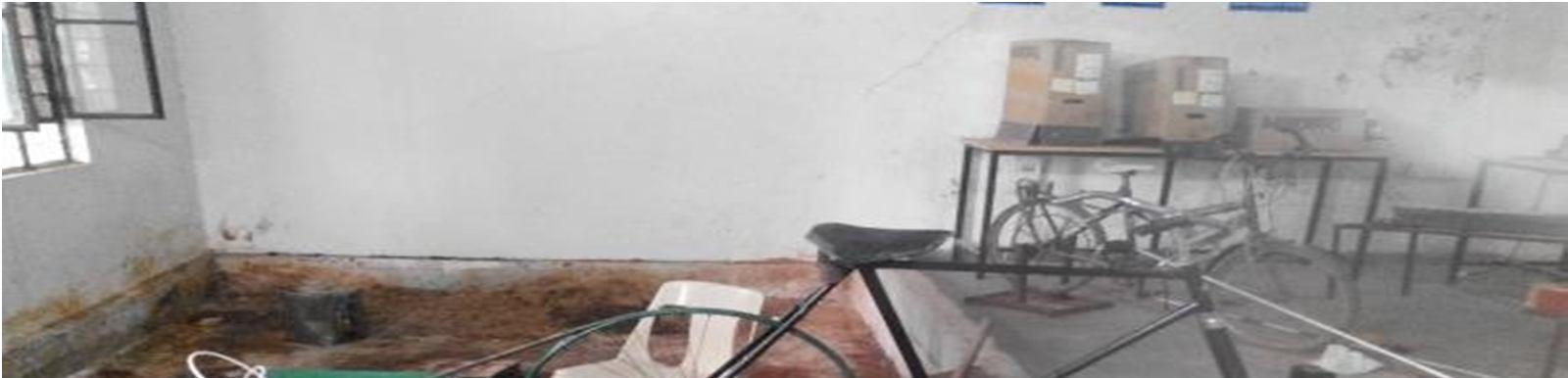
The setup of water purification comprising of three filters, viz. Sediment filter, Activated Carbon Filter and Post Filter and the RO filter was bought from market and assembled in our project as per our requirements.
a) Sediment Filter: Sediment filter is the first filter through which the water is passed and usually used toscreen out dust, sand, rust and other microscopic particles and are selected based on the particle size removed (for example, 2 microns to 100 microns). Forthis project we used the sediment filter of 5 micron which is sufficient for a household water supply[7].
b) Activated Carbon Filter: Activated carbon filter removes organics that can affect taste, odor and color reduces chlorine, Trihalomethanes (THM), Pesticides, Industrial solvents (halogenated hydrocarbons), Polychlorinated biphenyls (PCBs), polycyclic aromatic hydrocarbons (PAHs), radon gases. The efficiency of these filters is determined by the length of time the contaminants are in contact with the carbon. The lower the flow rate of the water, the moretime the contaminants will be in contact with thecarbon and the more adsorption will take place. Removal rates also are affected by the particle size. Activatedcarbon filters usually are rated by the size of the particles they are able to remove, measured in microns, and generally range from 50 microns (least effective) to 0.5 micron (most effective) [7].
For this project we used Activated Carbon filter of following specifications: Particle Size: 5 micron
c) Post Filter: This filter is generally called as second activated carbon filter and is usually placed after it to make water more clear before entering into the RO membrane.
Specifications: Particle Size 5 micron
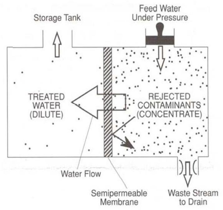
d) RO Membrane Filter: Osmosis is a natural process inwhich a liquid from a less concentrated solution flowsthrough a semipermeable membrane to a more concentrated solution. Reverse osmosis (RO) is just asit sounds, the reverse of osmosis. Pressure is applied on the more highly concentrated solution so that liquidflows from the higher concentrated solution to the lower concentrated solution. Figure 4 shows an illustration of this process. In this case the highly concentrated solution is dirty, undrinkable water. For this system, pressure is applied so that water molecules are forced through a 0.0001 micron semipermeable membrane. It is the most important unit of whole purification system as it is this filter which reduces theharmful dissolved solids. This consists of very fine pores through which water is passed very slowly and only after the required pressure is build up. The flow rate from this filter is the lowest and this is because ofthe minute size of pores through which water has to bepassed. Higher the time of contact of water with this membrane, the more purification will be achieved [4]. Figure 4: Reverse Osmosis Process
ISSN: 2321-9653; IC Value: 45.98; SJ Impact Factor: 7.538 Volume 10 Issue XII Dec 2022- Available at www.ijraset.com
During the working of RO system, in addition to an outlet of pure water, there is an outlet of waste water also which does not pass through filter and is taken from the system. To use this wastage of water by pumping it from a reservoir, we attached a small auxiliary setup consisting of a reservoir and a household cooler pump on the other side of the pumpshaft. Material for reservoir: Aluminum Sheet metal Dimensions: (380 × 190 × 190) mm A common household cooler pump run by the same shaft being used for diaphragm pump is used to pumpthe waste water from the reservoir. This water canthenbe used for cleaning or irrigation purposes.
The mechanism is tested by pedaling the bicycle for 5minutes and recording the data for pressure, RPM andTDS level of water. Following data were obtained during testing:
Sr. No. Time in sec. RPM Pressure in kgf/cm2 1. 30 930 0.91 2. 60 1010 1.05 3. 90 1030 1.19 4. 120 1150 1.26 5. 150 1050 1.19 6. 180 1240 1.33 7. 210 1130 1.33 8. 240 1270 1.47 9. 270 1390 1.61 10. 300 1440 1.68
Average RPM observed throughout cycling period: 1164 RPM
Average RPM required byhuman pedaling: 57 RPMTDS value before purification: 650 ppm
TDS value after purification: 150 ppm Thus it is seen that the mechanism is quite successful to provide the required RPM for the RO system to work. The system was able to achieve the TDS level of 150 after supplying initial water at 650 TDS. After5 minutes of cycling at an average pace of 1200 RPM, the system was able to produce 0.4 liter of water at anaverage flow rate of 0.08 liter/minute.
ISSN: 2321-9653; IC Value: 45.98; SJ Impact Factor: 7.538 Volume 10 Issue XII Dec 2022- Available at www.ijraset.com
The idea of Human Powered water purification system aims at providing safe drinking water with the minimum utilization of resources for promoting the health and overall wellbeing of societyas a whole. Theproject was initiated with the specific objectives of efficient water purification using only Human Power, minimal setup and the affordable cost of installation and maintenance. A mechanism is designed to provide the required RPMusing human power to run the pump which supplies pressurized water to the RO filter and pure water is obtained. The system has shown positive results to achieve the desired flow rate and pressure to run a reverse osmosis system successfully and hence it has paved a way for the harnessing of human power for other applications as well. Some of the possible areas of applications where this concept can be extended in future are:
1) People in villages have to travel longdistances to collect water from wells. So thissystem can be modified to be used as a commuting vehicle as well as a portable water collection device in rural areas to take out water from wells.
2) It can be used as multipurpose urban cyclingequipment especially in the commercialgyms and health clubs.
3) USB charging equipment can be run by the other end of shaft which can be used to charge cell phones.
4) A small dynamo can be coupled to the shaft which can be used to charge small batteries for use in emergency.
5) The belt-pulley mechanism used in the system may be used to run a wooden lathe, auxiliarypump, etc.
[1] EPA, “The History of Drinking Water Treatment”, Executive Order EPA-816-F-00- 006, February, 2000, Office of Water, United States Environmental Protection Agency,
[2] Engebrecht,C., Metzger, I. , Petrucci, M., Porterfield, C., 2007, “ Cool WaterPurification Project”, Project Report,University of San Diego, San Diego.
[3] “Water Contaminates”, 20 March 2011,
[4] Drake, D. and Solley, M., 2011, “HumanPowered Reverse Osmosis for Producing Potable Water for Developing Countries,”Proceedings of Ninth LACCEI Latin American and Caribbean Conference(LACCEI’2011), Medellin, Colombia, 1.
[5] Selection of Pumps”, 11 May, 2017.
[6] “3- Stage RO System”, 23 January 2010,
[7] Alvaro, E. and Kevin, M., 2004, “Literature Review of Feedback Control of Drinking Water Purification”, M. Tech. Thesis, Department of Electrical and ComputerEngineering The Ohio State University
[8] Ensink, J.H., Blumenthal, U.J., Brooker, S., 2008, “Wastewater Quality and The Risk of Intestinal Nematode Infection in Sewage Farming Families in Hyderabad, India”, TheAmerican journal of tropical medicine and hygiene, 79 (4). pp. 561-7.