10 VIII August 2022 https://doi.org/10.22214/ijraset.2022.45886
The most punctual wheels were made of a strong bit of wood. In its crude frame, a wheel is a round square of a hard and strong material at whose middle has been drilled a roundabout opening through which is set a pivot bearing about which the wheel turns when a minute is connected by gravity or torque to the wheel about its hub, haggle along these lines making together one of the six basic machines. At the point when put vertically under a heap bearing stage or case, the wheel turning on the flat hub makes it conceivable to transport substantial burdens; when set on a level plane, the wheel turning on its vertical hub makes it conceivable to control the turning movement used to shape materials (e.g. a potter's wheel); when mounted on a section associated with a rudder or a suspension mounted on different wheels, one can control the course of a vessel or vehicle (e.g. a ship's wheel or directing wheel); when associated with a wrench, the wheel delivers or transmits vitality (e.g. the flywheel)
II. PREPARATION OF ALLOY WHEEL
International Journal for Research in Applied Science & Engineering Technology (IJRASET) ISSN: 2321 9653; IC Value: 45.98; SJ Impact Factor: 7.538 Volume 10 Issue VIII Aug 2022 Available at www.ijraset.com 60©IJRASET: All Rights are Reserved | SJ Impact Factor 7.538 | ISRA Journal Impact Factor 7.894 | Design, Development and Analysis Wheel Rim by using Composite Material
TPCT College of Engineering Osmanabad
A. Types Of Alloy Wheels
1) Wire Spoke Wheel: Wire talked wheel is a central where the outside edge some bit of the wheel (edge) and the turn mounting part are associated by various wires called spokes. The present autos with their high quality have made this kind of wheel make old. This sort of wheel is so far used on incredible vehicles. Light composite wheels have making starting late, an outline to offer emphasis to this spoke effect to fulfill customers frame requirements.
Sayyed Fayaz Sayyed Musheer , Dr V.V. Mane2
1
I. INTRODUCTION
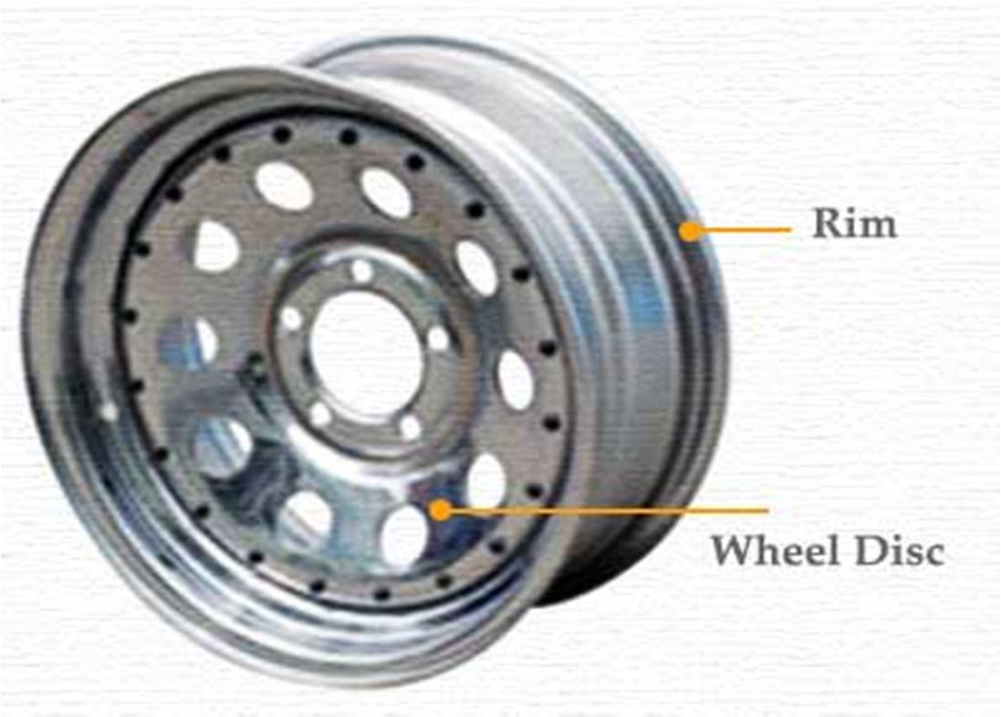
2) Steel Disc Wheel: This is a rim which hones the steel made rim and the wheel into one by joining (welding), and it is utilized for the most part for traveller vehicles particularly unique gear tires.
3) Light Alloy Wheel: These wheels depend on the utilization of light metals, for example, aluminum and magnesium has come to be prevalent in the market. This wheel quickly winds up noticeably standard for the first gear vehicle in Europe in 1960's and for the substitution tire in United States in 1970's. The benefits of each light combination wheel are clarified as beneath.


3) Adds mass (damped mass for driving comfort).
1) Transfers torque (braking and acceleration).
International Journal for Research in Applied Science & Engineering Technology (IJRASET) ISSN: 2321 9653; IC Value: 45.98; SJ Impact Factor: 7.538 Volume 10 Issue VIII Aug 2022 Available at www.ijraset.com 61©IJRASET: All Rights are Reserved | SJ Impact Factor 7.538 | ISRA Journal Impact Factor 7.894 |
7) Composite Material Wheel: The composite material wheel is not the same as the light amalgam wheel, and it is produced for the most part for low weight. However this wheel has deficient consistency against warm and for best quality. Advancement is proceeding.
5) Magnesium Alloy Wheel: Magnesium is around 30% lighter than aluminium and furthermore honourable with respect to measure steadiness and effect resistance. However,its utilize is for the most part confined to hustling, which needs the elements of weightlessness and high quality to the detriment ofweathering resistance and design decision, and so on contrasted and aluminium. As of late, the innovation for throwing and fashioning is enhanced, and the erosion resistance of magnesium is likewise making strides. This material is getting uncommon consideration because of the recharged enthusiasm for vitality preservation.
2) Support mass (support the mass of the motor vehicle).
6) Absorbs impact (road hazards).
7) Conserves energy (potential energy in momentum).
Depending upon the application where wheel rims are used its design requirement also changes. Design of agricultural vehicles
Wheel rims far differ from the passenger vehicles. But basic design requirements are similar. Basic requirements of any vehicle wheel rim includes following mechanical characteristics.
1) Structural Stiffness
2) Static Strength (Deformation under all types of loads).
3) Fatigue strength. 4) Impact Strength.
III. CLASSIFICATION OF CAR WHEELS
A. Steel Wheels
4) Aluminium Alloy Wheel: Aluminium is a metal with components of phenomenal daintiness, warm conductivity, and rust encounter, physical characteristics of throwing, low warmth, machine handling and reutilizing, and so on. This metals fundamental preferred standpoint is decreased weight, high exactness and design decisions of the wheel. This metal is valuable for vitality safeguarding in light of the fact that it is possible to re cycle aluminium effort Lesley.
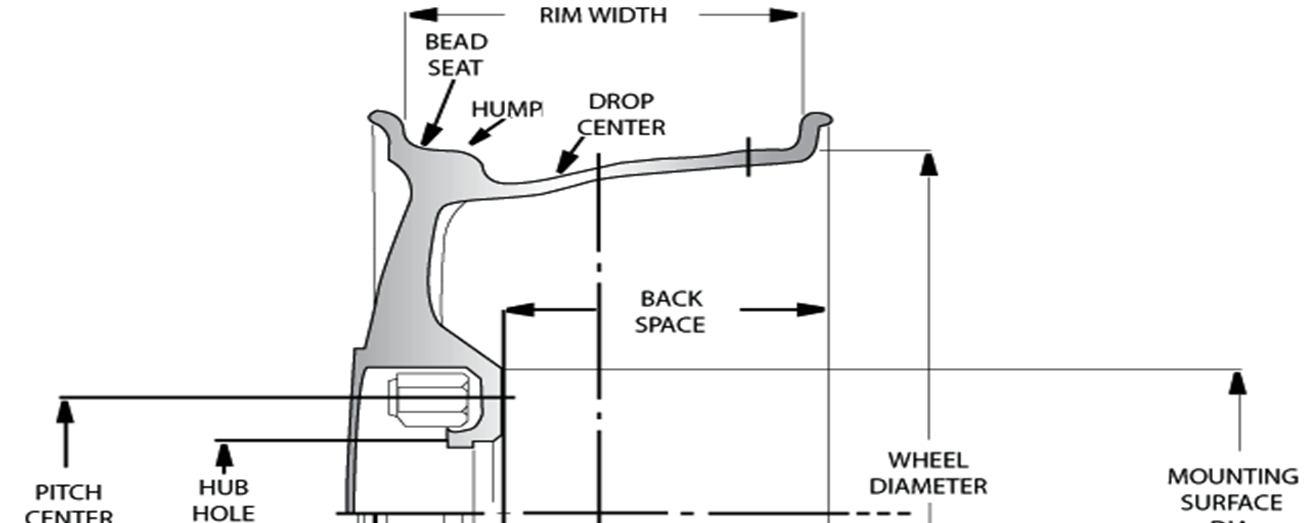
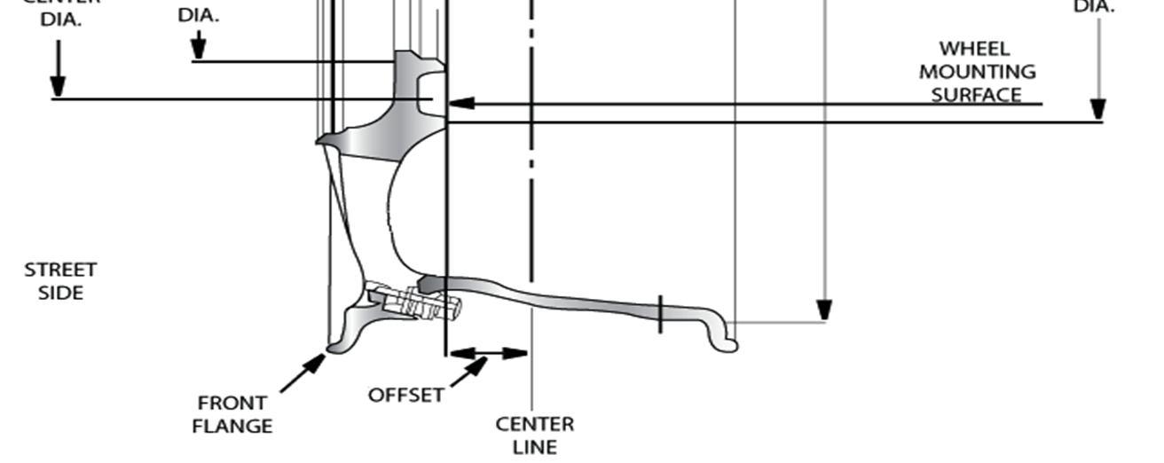
All steel wheels consist of two pressed components, the rim and the wheel disc, which are welded together. The rim is the part on which tyre is mounted. Its dimensions shape and condition must suitable to satisfactorily accommodate the particular tyre required for the vehicle. The wheel disc is the supporting member between the vehicles hub and the rim. Its dimensions shape and location in the rim must be suited to the design of the wheel hub and the suspension geometry of the vehicle to which it has to be mounted. The purpose of the rim is to provide a firm base on which to fit the tyre. Four vital dimensions are involved. They are the wheel diameter (a precise fit between tyre and rim is of utmost importance), the rim width, the flange height (designed to give adequate support to the tyre beads without changing the flux area of the side wall) and the rim well (to facilitate the easy mounting and demounting of the tyres.
4) Dissipates heat (from braking).
In its basic form a wheel rim is a transfer element between the tyre and the vehicle. The following are the main functions of a wheel rim:
C. Basic Requirement of Wheel Rims
Car wheels are divided in to two main categories, steel wheels and alloy wheels. Alloy wheels are often fitted standard during the manufacturing of modern vehicles.
B. Functions Of A Wheel Rim
5) Adds value.
6) Titanium Alloy Wheel: Titanium is an excellent metal for erosion resistance and quality (around 2.5 times) contrasted and aluminium, however it is sub par because of machine handling, designing and more cost. It is still in the improvement arrange despite the fact that there is some use in the field of hustling.
Because the inside diameter of the tyre must fit precisely onto the rim, it would be impossible for the inside diameter of the tyre to pass over the large diameter of the tyre rim without causing damage to the beads. Forcing the tyre bead into the rim well opposite to the fitting head of the machine during the fitting or removal process, allows the tyre bead enough purchase to pass over the rim flange.
Steel Wheel B. Alloy Wheels Alloy wheels are often incorrectly referred to as magnesium or “Mag” wheels. Magnesium is used in alloys. However, they are almost found only in racing rims meant for the track. Its brittle and highly flammable qualities make it unsuited as a road rim. Low pressure, die casted aluminium alloy wheels are used and offer certain benefits over steel wheels. It is possible to design alloy wheels that alloy for the better air flow over the brakes and that are also slightly lighter and visually more appealing than steel wheels. Because alloy is lighter than steel, wider rims can be used without sacrificing unsprung weight. Aluminium Wheel
International Journal for Research in Applied Science & Engineering Technology (IJRASET) ISSN: 2321 9653; IC Value: 45.98; SJ Impact Factor: 7.538 Volume 10 Issue VIII Aug 2022 Available at www.ijraset.com 62©IJRASET: All Rights are Reserved | SJ Impact Factor 7.538 | ISRA Journal Impact Factor 7.894 |
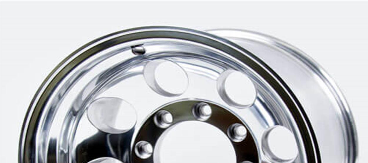
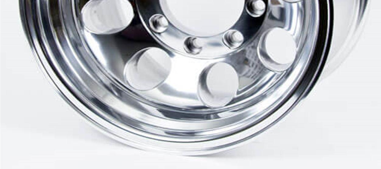
Higher cars typically come with alloy wheels rather than basic steel wheels covered with cub hap, called mag wheels because when they are first came out they are made of alloy of magnesium. Today’s alloy wheels are made with aluminium alloy, which is more durable. Aluminium alloys wheels are not only more attractive than standard steel wheels; they are also the fraction of their weight. And therefore require less energy to rotate; this contributes to greater fuel efficiency, as well as better handling acceleration and Manufacturingbreaking.
begins with high grade aluminium alloy, containing 97%Al. A furnace heats the ingests to 750oC. They liquefy in about 25min. The molten Al then flows directly to a mixer in which they inject argon gas which enables them to remove the hydrogen; this increases the density making the Al less porous when solidified. After adding powder titanium, mg, and other metallic elements to further strengthen the Al they blend in flux, a material which draws aluminium oxide to the surface. They skim off the impurity along with the flux and the liq al is ready for casting. The wheel mould is made of high strength steel; it’s actually a set of three moulds. The upper mould which forms the inside face of the wheel, the fore part side mould which forms the wheels edge, and the lower mould which forms the face. It takes 3 to 4 weeks to produce a mould. The casting machine is designed to fill the mould from the bottom with pressurised injection. Injecting upward rather than from top, reduces the risk of air bubbles which causes defects. Right before casting the molten metal flows through a filter sheet, made of high temperature resistance ceramic. This traps aluminium oxide. Once cast the aluminium takes about 7 to 10min to solidify. Then the mould automatically opens, releasing the newly cast wheel.Workers submerge it in Luke worm water for few min, this cools it down to be handled. The wheel undergoes a complex heat treatment process that takes 12hr to fnish.first they heat the wheel to 500 C. this rearrange the molecular structure strengthening the metal. Then they submerge the wheel in 80C water for 30 seconds in the process of quenching. Then they reheat the wheel, ie, to180C for 9hrs for further stabilising the metal. The wheel does not come out of the mould in perfect condition. The edges are rough. So it is mounted on the computer guided lathe and refines it to the technical drawings. And for more intrikit face of the wheel, the worker manually trims the edges with a blade. The shape is now finalised, it’s time to test the wheel to make sure its air tight. While pumping air into the wheel they submerge it into the water to determine any pin holes. No air bubbles, the wheel is forwarded for painting to avoid corrosion. The factory test randomly 2 or 3 for wear out of all the produced castings.
V. SELECTION OF MATERIAL
Wide varieties of materials are available in the market can be used for wheel rims. In ancient period wheel rims are manufactured from single piece wooden material, after some millennium metals are evolved and a circular ring are mounted over wooden spoke wheel rim in order to avoid the wear of wheel due to road surface. At the end of eighteenth century a wire spoke wheel rims was used in an automobile after evolution of first engine and car.
1) Aluminium Alloy: Aluminium is a metal with features of excellent lightness, thermal conductivity, rust confrontation, physical characteristics of casting, low heat, machine processing and reutilizing, etc. This metals main advantage is decreased weight, high precision and design choices of the wheel. This metal is useful for energy preservation because it is possible to re cycle aluminium easily.
International Journal for Research in Applied Science & Engineering Technology (IJRASET) ISSN: 2321 9653; IC Value: 45.98; SJ Impact Factor: 7.538 Volume 10 Issue VIII Aug 2022 Available at www.ijraset.com 63©IJRASET: All Rights are Reserved | SJ Impact Factor 7.538 | ISRA Journal Impact Factor 7.894 | IV. PRODUCTION OF ALLOY WHEELS
Apart from mechanical properties there are some important factors must be considered while selecting a material for wheel rim. We have taken four different types of materail in our project such as, aluminium alloy, Magnesium alloy, Titanium Alloy, Forged steel alloy.
Wire spoke wheels used up to 1920. After First World War rim design revolution takes place and wire spoke wheels replaced by a sheet metal and casted wheel rims. However rim manufacturing process changed its testing methods as well as basic design requirements are same yet. Now a day following materials are generallyused for wheel rim: Al alloys, Mg alloys, Steel 1008, forged steel, Carbon fibers.
2) Magnesium Alloy: Magnesium is about 30% lighter than aluminium and also admirable as for size stability and impact resistance. However, its use is mainly restricted to racing, which needs the features of weightlessness and high strength at the expense of weathering resistance and design choice, etc. compared with aluminum.
3) Titanium Alloy: Titanium is an admirable metal for corrosion resistance and strength (about 2.5 times) compared with aluminium, but it is inferior due to machine processing, designing and more cost. It is still in the development stage even though there is some use in the field of racing.. In the real service conditions, the determination of mechanical behaviour of the wheel is important, but the testing and inspection of the wheels during their development process is time consuming and costly.
The major casting processes for wheels are: Low pressure die casting (mainly) Gravity permanent mould casting (less used) Squeeze casting process (marginally used) Rarely used are the following processes: Counter pressure die casting Casting forging (Cobapress) Thixocasting
For economic reasons, it is important to reduce the time spent during the development and testing phase of a new wheel. A 3 D stress analysis of Aluminium wheels of the car involves complicated geometry. Therefore, it is difficult to estimate the stresses by using elementary mechanical approximations. For this purpose, Finite Element Analysis (FEA) is generally used in the design stage of product development to investigate the mechanical performance of prototype designs. FEA simulation of the wheel tests can significantly reduce the time and cost required to finalize the wheel design. Thus, the design modifications could be conducted on a component to examine how the change would influence its performance, without making costly alteration to tooling and equipment in real production.
Casting, forging, press working are the three main manufacturing processes are used for the production of any type of automobile wheel rim. In any wheel rim types of defect occurred such as manufacturing defect and service defects. The defects introduced during the manufacturing process are known as manufacturing defects while defects introduced during service life of wheel rim are known as service defects. In casting several types of casting processes are used such as low pressure and high pressure die casting, gravity die casting, squeeze and centrifugal. Generally casting introduces so many types of defects such as blow holes, subsurface defects cavities, porosity and uneven shrinkage. Parameters of wheel rim design vary as manufacturing process changes. Forging is one of the excellent manufacturing methods for better quality rim, but this method is very costlier as compare to other methods. Rims of heavy vehicles such as truck, trolleys and tempos are manufactured from forging method. Press working method is used to manufacture the rims which are used for light duty vehicles, scooters, auto rickshaws etc.Generally press worked rims are two piece wheel rims.
International Journal for Research in Applied Science & Engineering Technology (IJRASET) ISSN: 2321 9653; IC Value: 45.98; SJ Impact Factor: 7.538 Volume 10 Issue VIII Aug 2022 Available at www.ijraset.com 64©IJRASET: All Rights are Reserved | SJ Impact Factor 7.538 | ISRA Journal Impact Factor 7.894 |
VI. MANUFACTURING PROCESSES OF WHEEL RIMS
A. Casting Processes Among aluminium wheels, cast ones represent more than 80% in Europe, 85% in USA for passenger cars and light trucks, and 93% in TheirJapan.main advantages, when compared to steel or other aluminium wheels are: A high styling versatility Weight (equal or less than steel without styling) Dimensional accuracy (mass distribution) Recycling ability Static and dynamic behaviour
4) Forged Steel Alloy: Forged steel is manufactured in a hot forging operation. This involves heating medium carbon steel billets to 2,400˚F or about 200˚ below the melting point of steel. Then, the red hot metal is hit with high tonnage forging hammers to enhance the grain structure and increase the tensile strength of the wheel. Precision machining then completes the product with rounded edges to finished tolerances. Steel wheels are made with an alloy of iron and carbon. They are heavier but they’re more durable and can be easier to repair and refinish. Because of the way they’re made cut out on a press and welded together they don’t offer all the aesthetic spoke choices of other wheel types. Though their heavier weight may dampen acceleration, agility and fuel efficiency, steel wheels can offer more resistance to impact cracks. They can also be more resistant to damage from deicers, gravel and brake dust, making them more popular for winter driving. Steel wheels are generally less expensive than aluminum wheels.
The manufacturing process permits a maximum brake caliper room in combination with tight dimensional tolerances, low weight and high strength and toughness. Forging aligns the grain structure along the direction of the material’s flow, thereby permitting exploitation of strength and toughness properties of the alloy to the maximum extent. As a result, forged wheels are more damage tolerant w/r to misuse.
3D dimensional controls
Processing after casting After casting, wheels are 1) 100% x ray inspected and then eventually heat treated prior to machining.This step is followed by a pressure tightness testing before drilling valves and bold nut holes after a cosmetic inspection wheels are then,
C. Sheet Metal Process
1) A strip of sheet metal, cut to the required length, is made into a round with the ends butt welded together using a pressure welding machine. After removal of the weld flash, the rims are shaped in a series of rolling operations.
B. Forging
3) Joining the rim to the nave is done by means of a pulsed MIG process. After joining, the wheels are surface treated, i.e. pre treatment to produce a conversion coating followed by an electro dip coating.
Forged aluminium wheels are one piece wheels formed from a single block of metal by hot forging, hot or cold spinning and machining operations. The forging process permits flexibility in design of the styled disk, similar to cast wheels.
5) Etching and painting.
In relation to castings forged materials exhibit decidedly higher fatigue resistance due to absence of pores and because of a fine, homogeneous microstructure. While cast wheels are performing according to the same load and endurance specifications as forged wheels, the latter are more tolerant to overloads as may be experienced in sports cars.
International Journal for Research in Applied Science & Engineering Technology (IJRASET) ISSN: 2321 9653; IC Value: 45.98; SJ Impact Factor: 7.538 Volume 10 Issue VIII Aug 2022 Available at www.ijraset.com 65©IJRASET: All Rights are Reserved | SJ Impact Factor 7.538 | ISRA Journal Impact Factor 7.894 |
2) The wheel nave is formed in several steps on a transfer press using a deep drawing process or stamped on a forging machine.
2) flow turning (hot spinning) 3) solution heat treatment and ageing 4) machining, drilling, deburring (optional diamond turning)
2) Painted or varnished, this operation including a pre treatment (degreasing, phosphatizing and/or chromating…).
In addition, the dense wrought microstructure permits high gloss diamond machining and polishing of the decorative hub faces.
The traditional wheel forging concept included several forging operations, rough machining, splitting, flow turning, heat treatment, final machining and numerous additional finishing steps, depending on design requirements. As a result, styling dominates weight and costs are considerable, (s. LINK). On the other hand, if low weight and low costs are prime targets, then fabrication technologies must dictate the styling limits.
3) Dynamic balance checking, 4) Bending and rim roll fatigue as well as 5) Impact tests are statistically performed.
1) 1 step forging, coining, piercing
The standard alloys used are the heat treatable wrought alloys: EN AW AlSi1MgMn (6082) in Europe AA 6061(AlSiMgCu) in USA
Following this reasoning rigorously, a production concept “Light Forged Wheel” was developed (Otto Fuchs Metallwerke) and these wheels are used by Audi, BMW, DaimlerChrysler, Jaguar and Volkswagen.
Several millions of these wheels have been produced since 1995, with the following steps:
International Journal for Research in Applied Science & Engineering Technology (IJRASET) ISSN: 2321 9653; IC Value: 45.98; SJ Impact Factor: 7.538 Volume 10 Issue VIII Aug 2022 Available at www.ijraset.com 66©IJRASET: All Rights are Reserved | SJ Impact Factor 7.538 | ISRA Journal Impact Factor 7.894 | VII. DESIGN, ANALYSIS & RESULTS OF WHEEL RIM
5) Cooling: Whatever the type of wheel (cast, forged, strip, mixed wrought cast), aluminium dissipates heat more quickly than steel. Further, aluminium wheels act as a very efficient heat sink. This results in significant improvements of braking efficiency, and a reduced risk of tyre overheating.
6) Style: Weight Saving: Reduction of weight of the unsprung mass of vehicles is a key priority. A compromise has to be accepted if styling requirements dictate different production technologies (s. figure).
7) Dimensional: A perfect mass balance is a key parameter to avoid significant vibrations. As a result, cast and forged wheels are machined. Lightness also reduces vibrations of aluminium sheet wheels
ever
8) Corrosion: Cast and forged wheels are painted or lacquered after chemical conversion. Strip wheels are polished and varnished or also painted. Even at the uncoated iron/aluminium disk, or hub interface, no significant corrosion has been noticed for any
A. Design of Automobile Wheel Rim In the modeling of the passenger car wheel rim, it have been taken the rim from 60 series 195/60 R 14. SR.NO. Parameters Taken For Modeling 1 Rim Nomeclature 7 JJ 14 50 5 96.0 2 Flange Shape JJ 3 Rim Diameter 15 inch 4 Rim Width 8 inch 5 Offset 72mm 6 Pitch Circle Diameter 96mm 7 Hub Diameter 46mm 8 Number Of Bolt Holes 5 nos 9 Number of Spokes 5 nos Parameters for modeling wheel rim The flange height, rim width, bead seats and rim diameter are taken with standard dimensions.
Other design consideration includes Heat Dissipation, style and weight, dimensional tolerances and corrosion resistance. Rim material should be as light as possible so that unsprung weight gets directly reduced. Following properties should be considered while designing the Wheel rim.
Apart from mechanical properties there are some important factors must be considered while selecting a material for wheel rim
2) Static Behaviour: Yield strength is considered to avoid deformation under maximal axial efforts (accelerations and braking) and radial ones (plus turning). Misuse cases are considered in relation to tensile strength. Yield tests under pressure are also conducted to check this behaviour.
4) Crash Worthiness: Mainly, but not only, linked to stress/strain curves in large displacements. Crashworthiness is beginning to be now simulated. However impact tests systematically check the resistance to accidental collisions such as pavements impacts.
Design Consideration of Wheel Rim
3) Fatigue Behaviour: This is the most important parameter for dimensioning. Finite element software is systematically used during design. Service stresses are considered, including multi axial stresses as of recently. Rotary bending and rim rolling tests are used to verify these calculations.
1) Stiffness: Structural stiffness (design dependent) is the basic value to consider when designing an aluminium wheel to achieve at least the same vehicle behaviour as with an equivalent steel wheel.However, material stiffness (Young’s modulus) is very little depending on alloy and temperature.
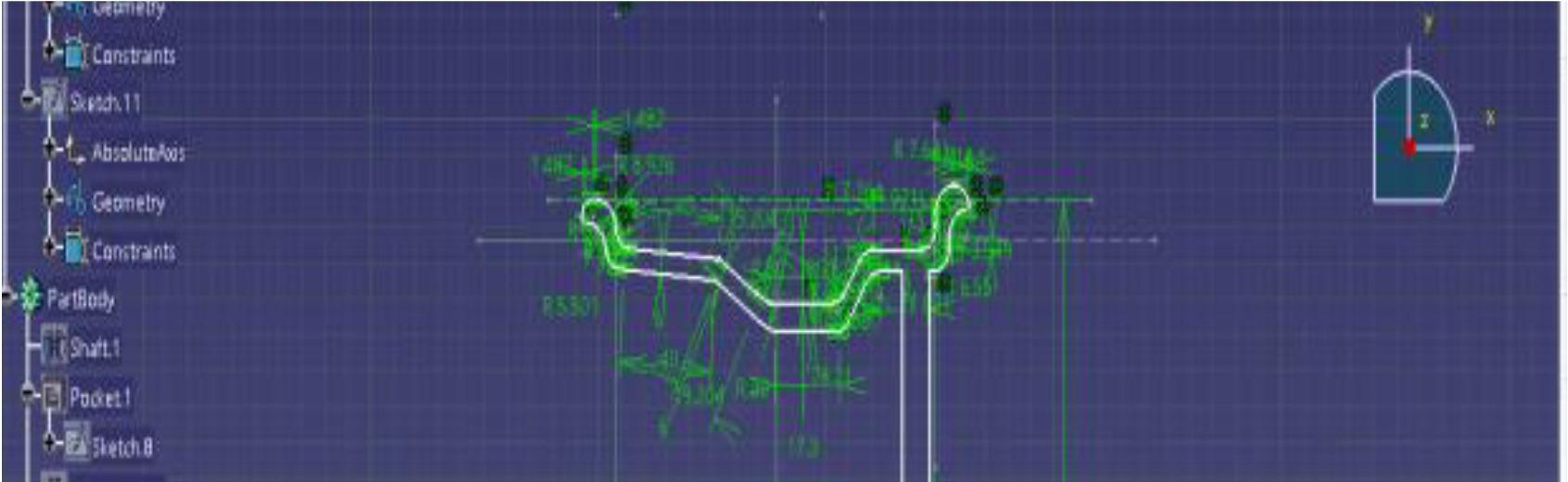
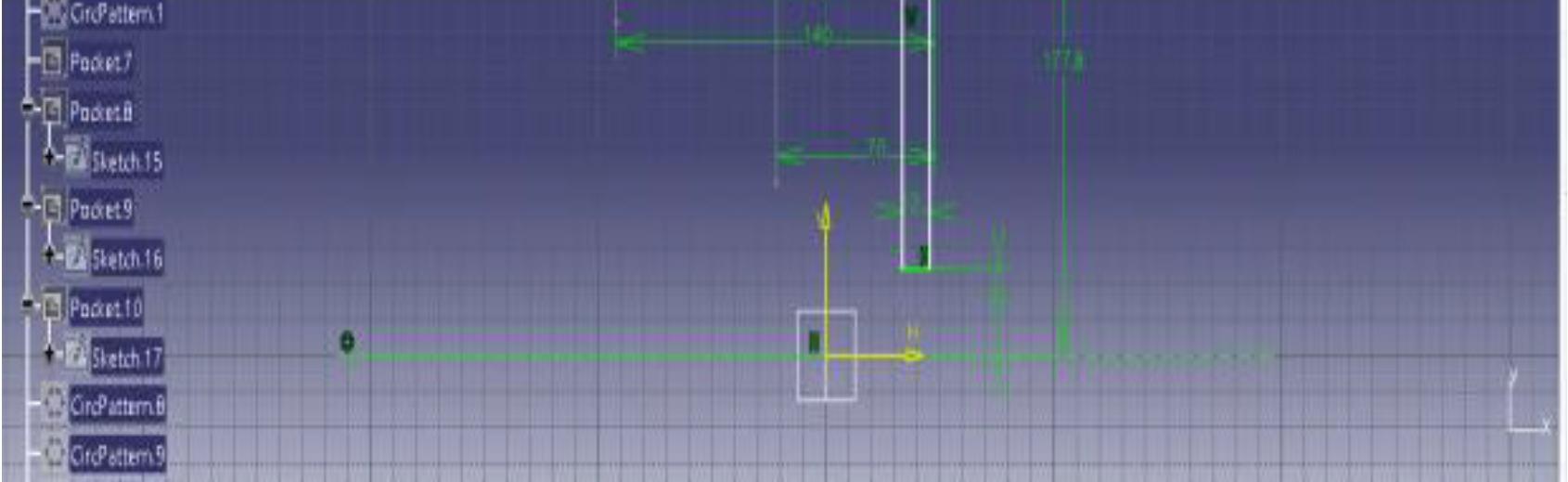
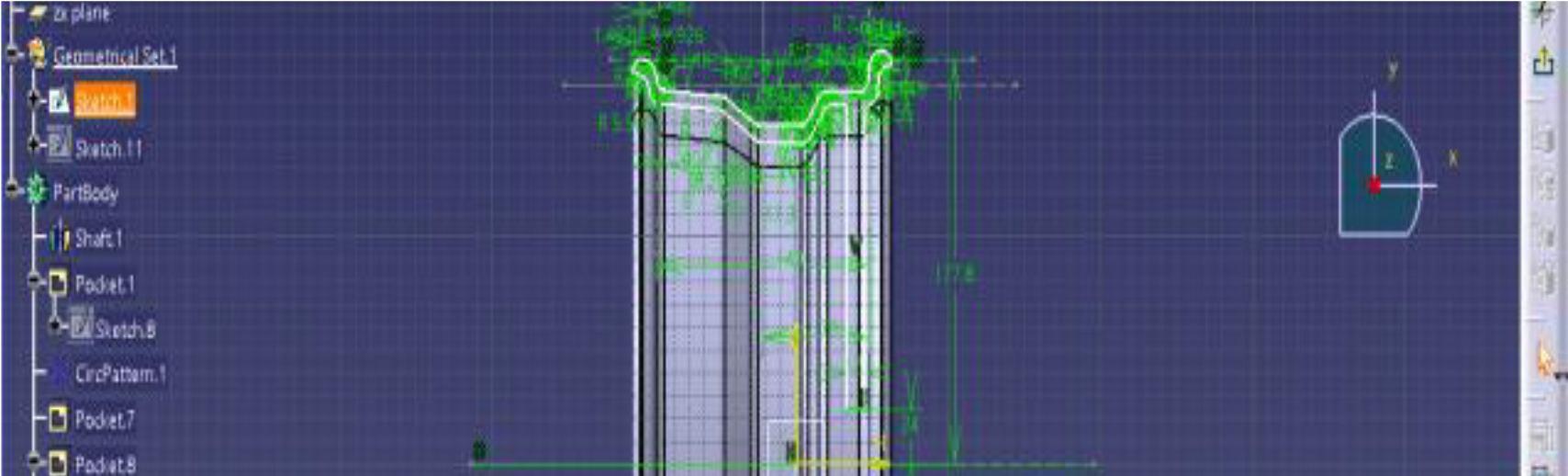
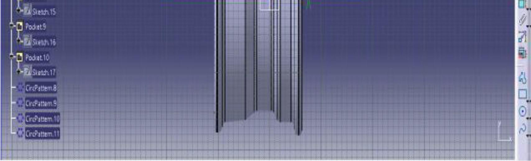
Modeling of Wheel Rim with J Contour Front View of Wheel Rim
The above figure shows the front view of the wheel rim. There is a clear view of the J counter and shaft operation is performed. The total diameter of the wheel rim is 355.6mm. The diameter is taken as per the continental data book. The pitch circle diameter taken is 5×98. Where 5 indicate the number of bolt holes and 98mm indicates the pitch circle diameter drawn. On the P.C.D the bolt holes are modeled for a wheel.
International Journal for Research in Applied Science & Engineering Technology (IJRASET) ISSN: 2321 9653; IC Value: 45.98; SJ Impact Factor: 7.538 Volume 10 Issue VIII Aug 2022 Available at www.ijraset.com 67©IJRASET: All Rights are Reserved | SJ Impact Factor 7.538 | ISRA Journal Impact Factor 7.894 | If the diameter of the hub is taken as 48 mm and the prime circle is taken as 25mm. The pitch circle diameter can be calculated as 25 x 2 + 48 PCD Therefore PCD =98mm
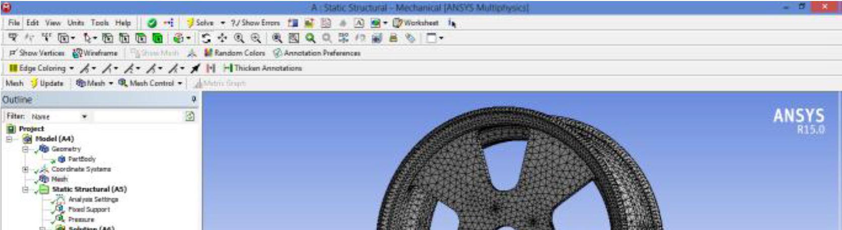
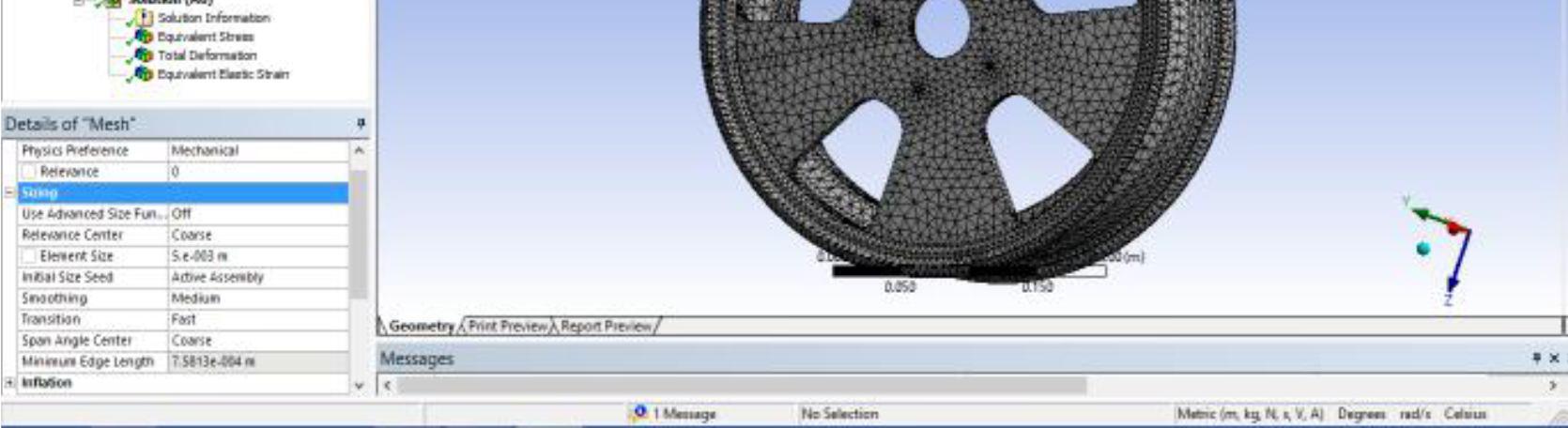
The imported file geometry undergoes meshing after which boundary conditions are applied to the physical domain. The fine mesh is considered for good results.
After the processing stage the boundary conditions are applied on the wheel rim. The loads are applied. As we seen earlier, the designed wheel rim is with the load index 86 i.e., it has the capacity to bear 530 kg. The load given here is 5200N. But here the wheel rim is considered as it is in static condition. When the car is in stationary, the entire load on the wheel rim will be distributed throughout the rim because of the air. The air is a medium which circulates the entire force acting on the rim.
International Journal for Research in Applied Science & Engineering Technology (IJRASET) ISSN: 2321 9653; IC Value: 45.98; SJ Impact Factor: 7.538 Volume 10 Issue VIII Aug 2022 Available at www.ijraset.com 68©IJRASET: All Rights are Reserved | SJ Impact Factor 7.538 | ISRA Journal Impact Factor 7.894 |
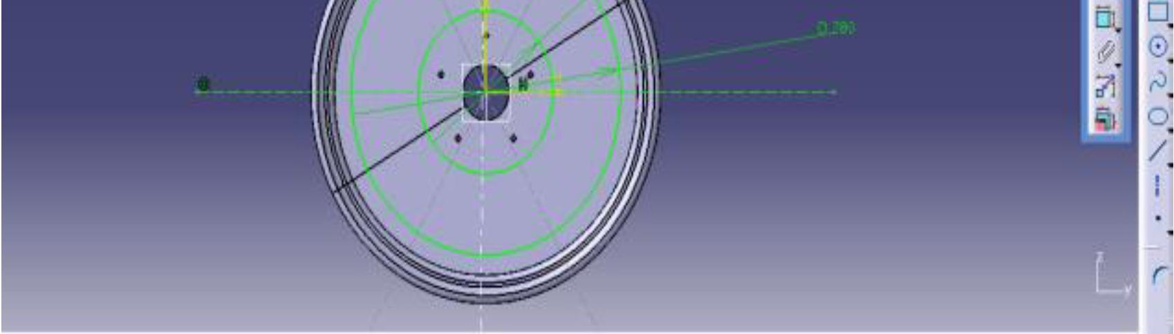
For the five bolts design and to model four spokes on the disc surface certain angles are taken. Total disc of 3600 made into equidistant parts and the spokes are drawn with an angle of 300.
B. Meshing
Modeling Of Spoke Design
Meshing of Wheel Rim

C. Response on Acceleration and Braking Wheels give more response on speeding up and braking, due to reduction in rotational mass of the vehicle
D. Brake Cooling is Increased
Whereas Unsprung weight incorporates the auxiliary members not upheld by the springs such as tyre and rim, brake and rear axle assemblies and other.[6] This typically incorporates some rate of weight of the suspension itself. It is an important concept because of lessening unsprung weight, wheels give more precisesteering and enhanced rotation attributes.
A. Reason for Selecting Lighter Materials
Reason for choosing these materials are not only for the reduction of weight of the rim, but also the considerable performance benefits, they are;
The material selections for wheel rim are light alloys and composite material, as the lighter materials reduce the weight of wheel saves material cost and increase the mileage of the vehicle.
B. Reduced Unsprung Weight
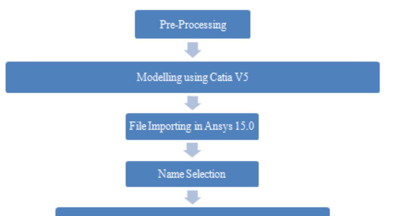
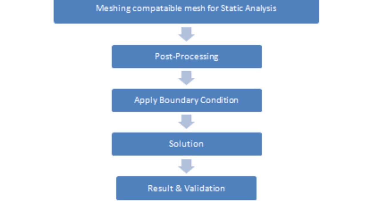
International Journal for Research in Applied Science & Engineering Technology (IJRASET) ISSN: 2321 9653; IC Value: 45.98; SJ Impact Factor: 7.538 Volume 10 Issue VIII Aug 2022 Available at www.ijraset.com 69©IJRASET: All Rights are Reserved | SJ Impact Factor 7.538 | ISRA Journal Impact Factor 7.894 | VIII. METHODOLOGY OF AN ALLOY WHEELS
The materials of light alloy and composites will reduce the danger of fade under rash 24riving, because of its brilliant heat conduction and enhanced heat dissipation from the brakes.Steps of Working
The term Sprung weight is used to portray the parts of a vehicle that are bolstered by the front and rear springs. They hang up the body, frame, engine, all fluids and the power train over the wheels. These are entirely substantial assemblies.
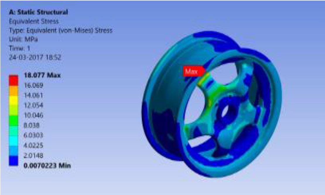
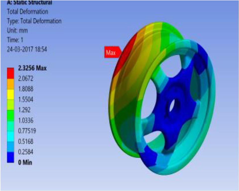
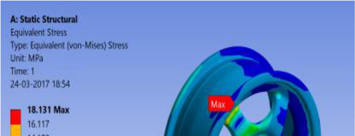
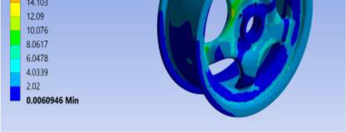
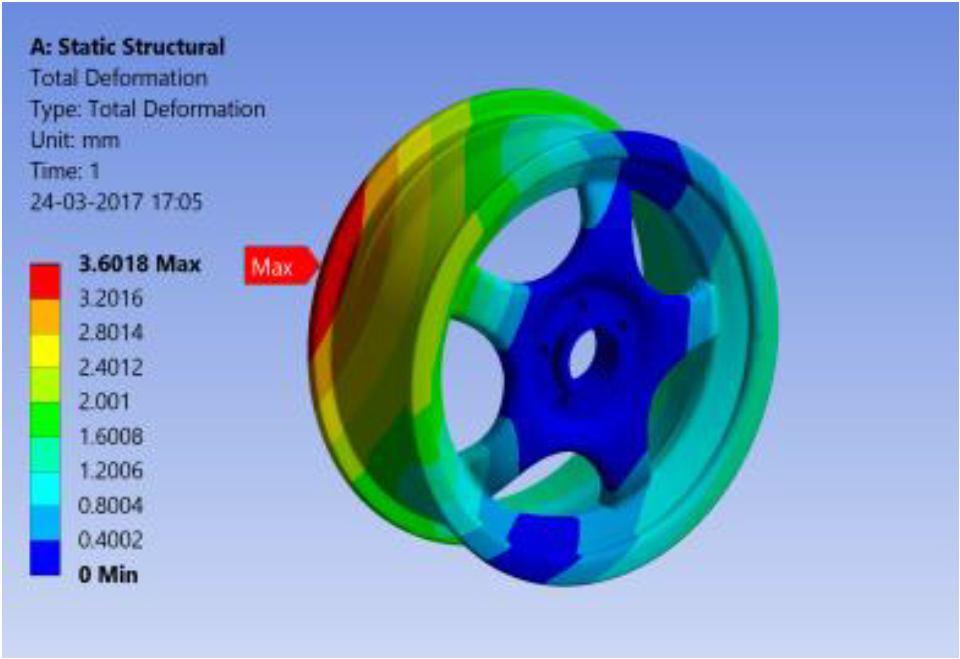
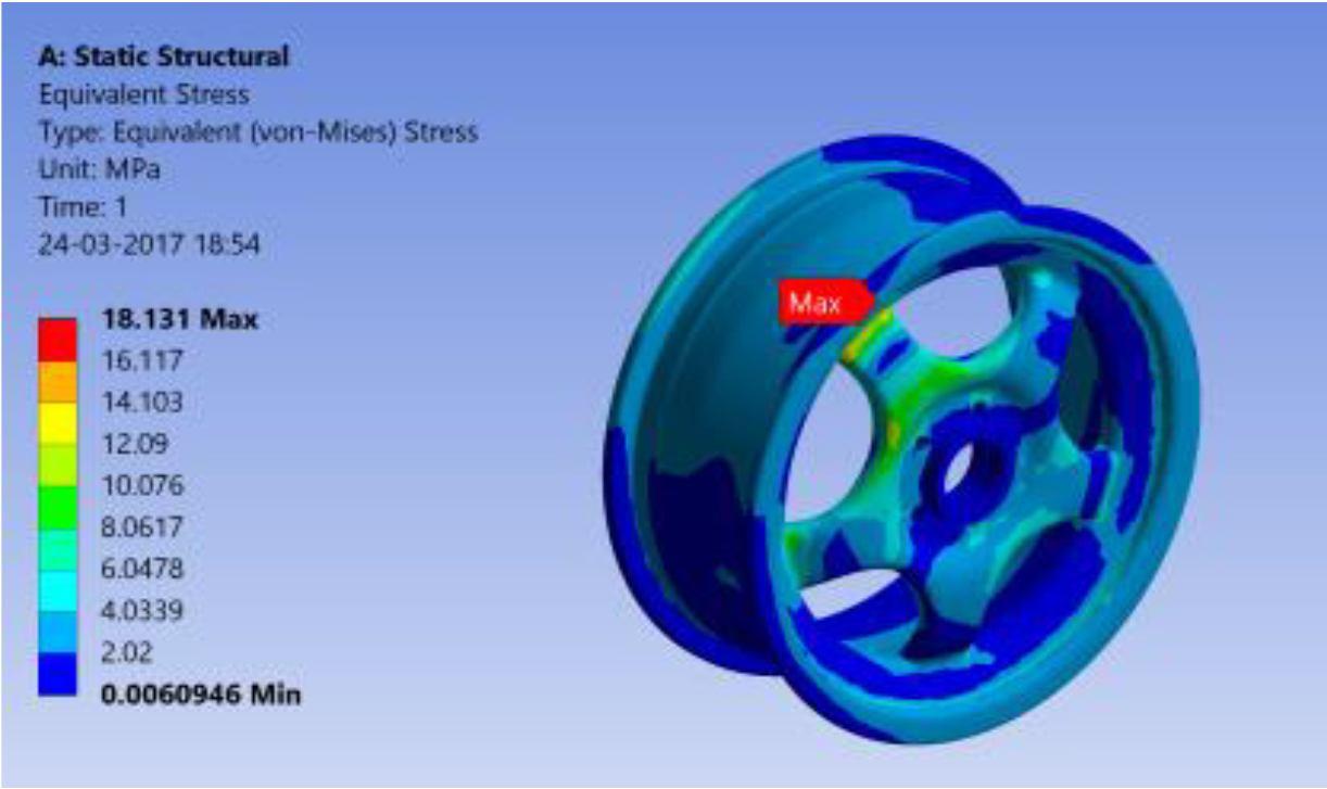
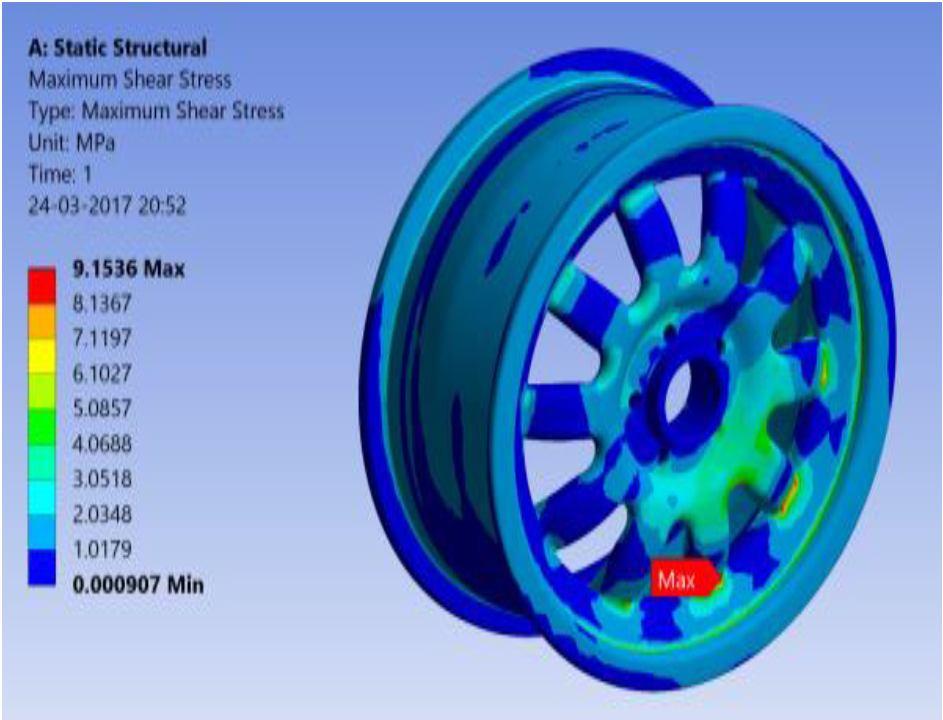
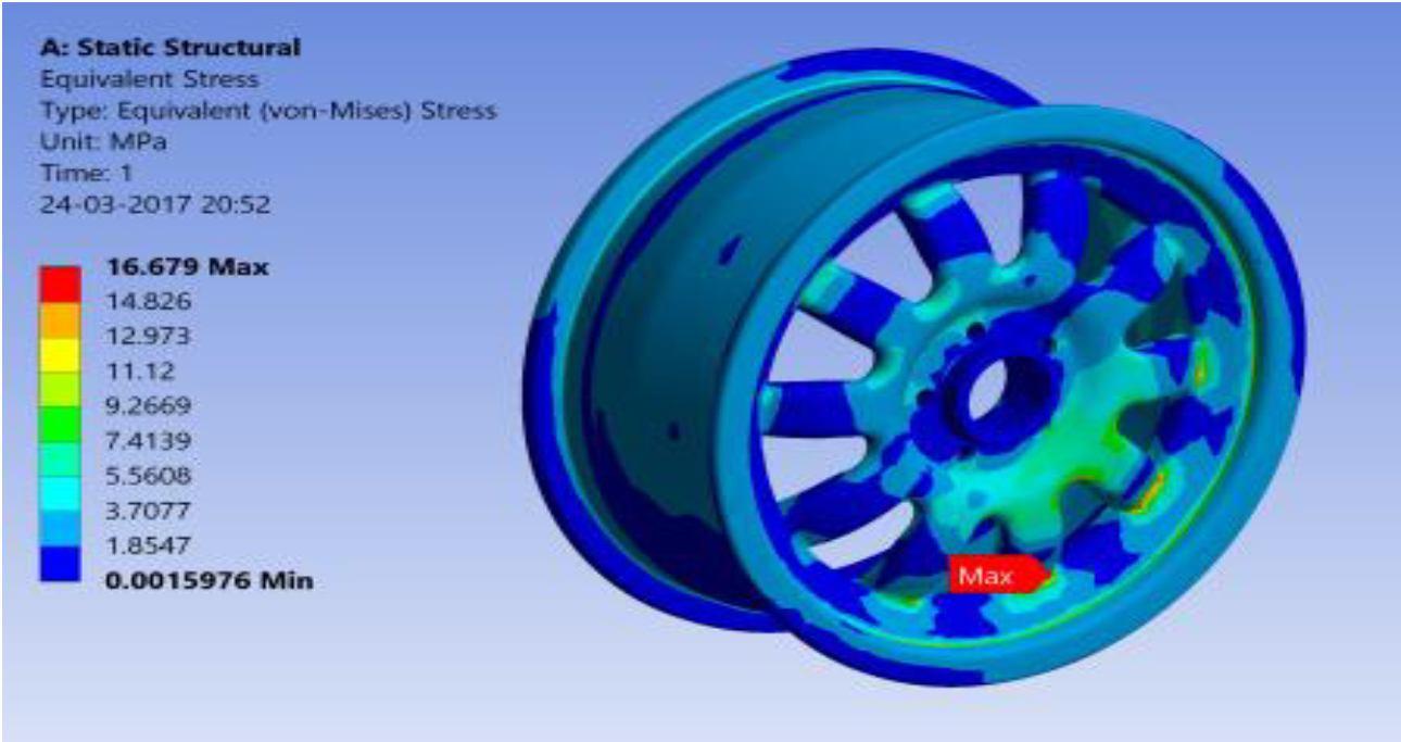
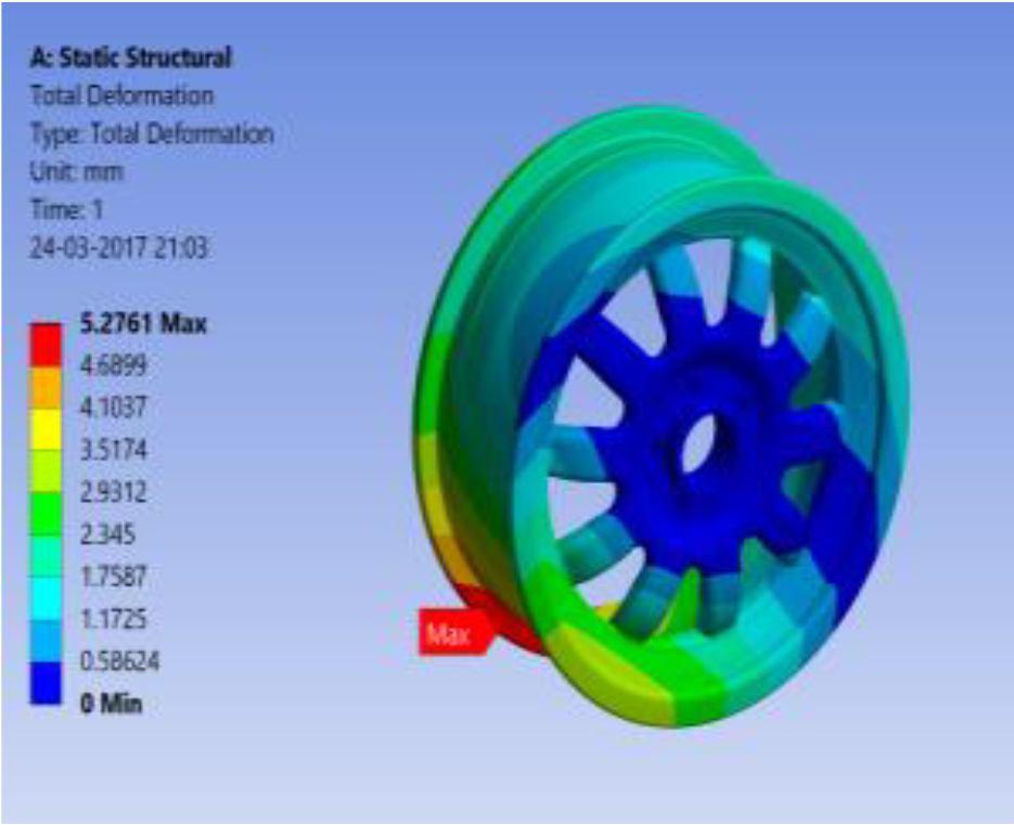
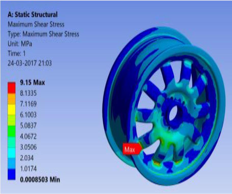
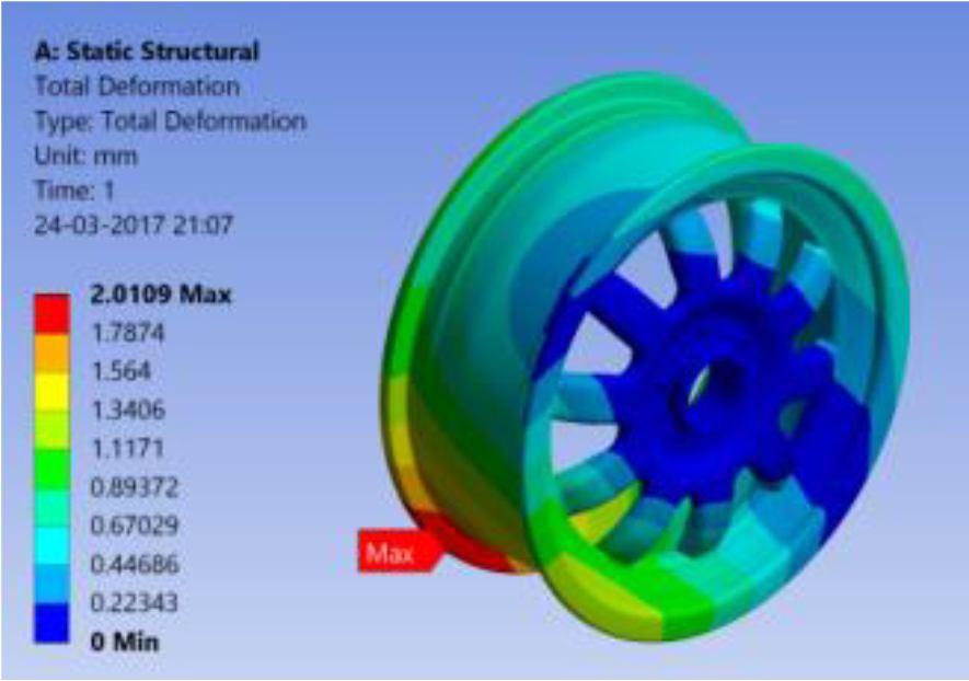
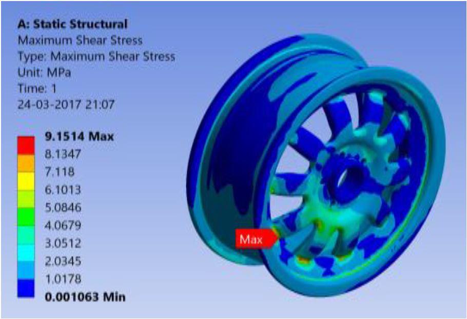
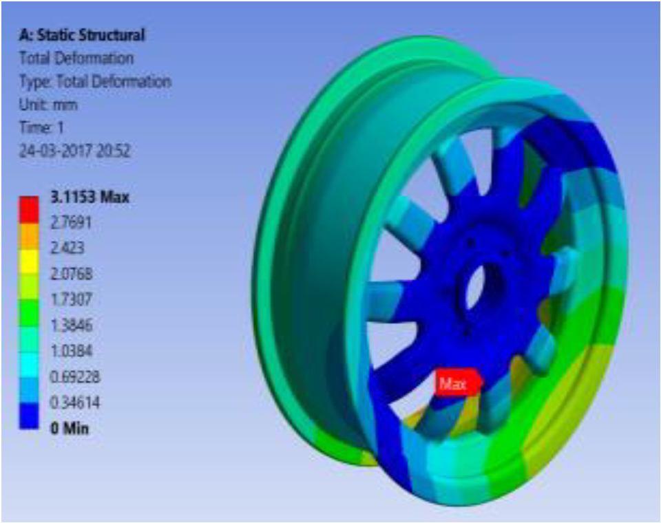
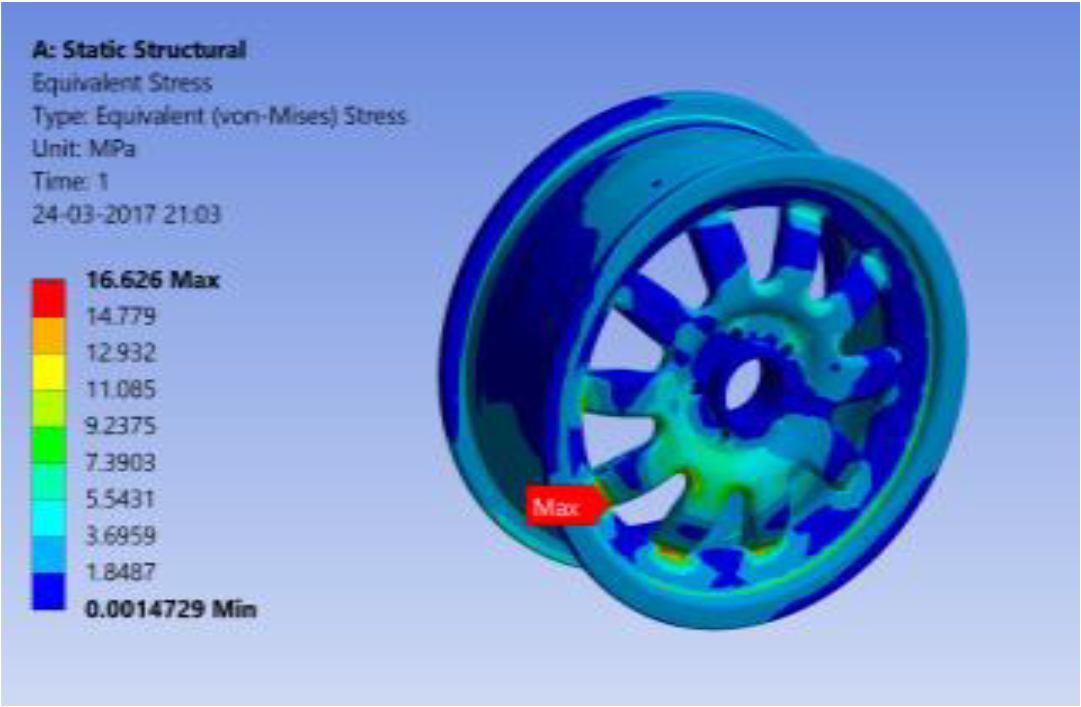
International Journal for Research in Applied Science & Engineering Technology (IJRASET) ISSN: 2321 9653; IC Value: 45.98; SJ Impact Factor: 7.538 Volume 10 Issue VIII Aug 2022 Available at www.ijraset.com 70©IJRASET: All Rights are Reserved | SJ Impact Factor 7.538 | ISRA Journal Impact Factor 7.894 | IX. ANSYS MODELS: A. Basic Design 1) Aluminium Alloy A] Total Deflection B] Maximum shear stress C] Equivalent Stress 2) Magnesium Alloy A] Total Deflection B] Maximum shear stress
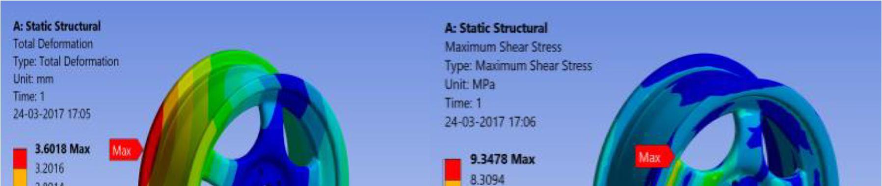
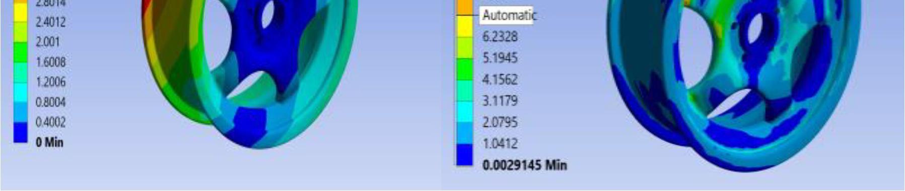
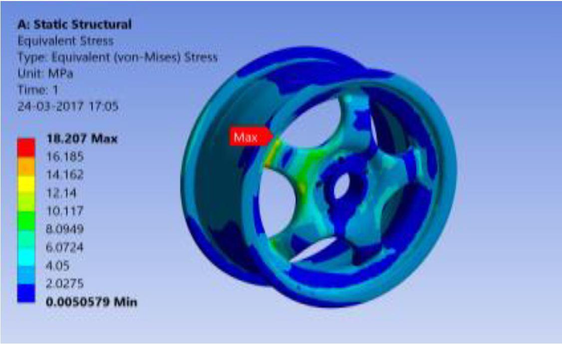
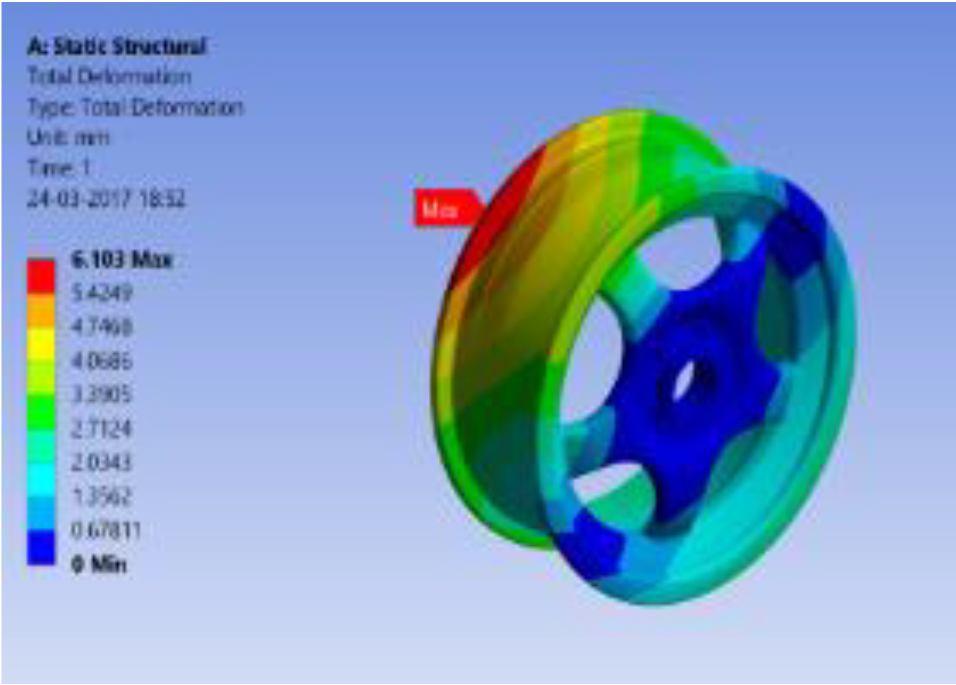
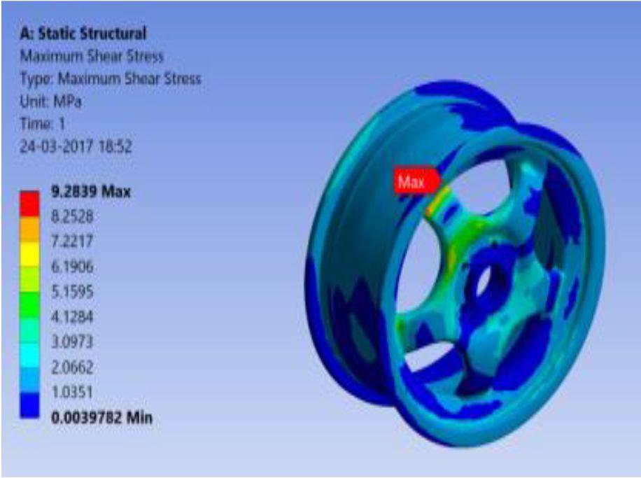
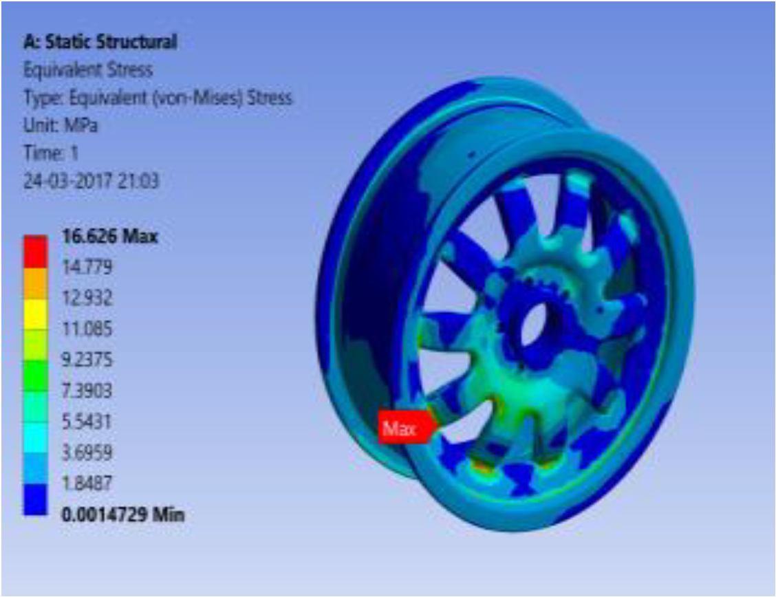
International Journal for Research in Applied Science & Engineering Technology (IJRASET) ISSN: 2321 9653; IC Value: 45.98; SJ Impact Factor: 7.538 Volume 10 Issue VIII Aug 2022 Available at www.ijraset.com 71©IJRASET: All Rights are Reserved | SJ Impact Factor 7.538 | ISRA Journal Impact Factor 7.894 | C] Equivalent Stress 3) Titanium Alloy A] Total Deflection B] Maximum shear stress C] Equivalent Stress

International Journal for Research in Applied Science & Engineering Technology (IJRASET) ISSN: 2321 9653; IC Value: 45.98; SJ Impact Factor: 7.538 Volume 10 Issue VIII Aug 2022 Available at www.ijraset.com 72©IJRASET: All Rights are Reserved | SJ Impact Factor 7.538 | ISRA Journal Impact Factor 7.894 | 4) Forged Steel Alloy A] Total Deflection B] Maximum shear stress C] Equivalent Stress B. Simple Model 1) Aluminium Alloy A] Total Deflection B] Maximum shear stress


International Journal for Research in Applied Science & Engineering Technology (IJRASET) ISSN: 2321 9653; IC Value: 45.98; SJ Impact Factor: 7.538 Volume 10 Issue VIII Aug 2022 Available at www.ijraset.com 73©IJRASET: All Rights are Reserved | SJ Impact Factor 7.538 | ISRA Journal Impact Factor 7.894 | C] Equivalent Stress 2) Magnesium Alloy A] Total Deflection B] Maximum shear stress C] Equivalent Stress
International Journal for Research in Applied Science & Engineering Technology (IJRASET) ISSN: 2321 9653; IC Value: 45.98; SJ Impact Factor: 7.538 Volume 10 Issue VIII Aug 2022 Available at www.ijraset.com 74©IJRASET: All Rights are Reserved | SJ Impact Factor 7.538 | ISRA Journal Impact Factor 7.894 | 3) Titanium Alloy A] Total Deflection B] Maximum shear stress C] Equivalent Stress 4) Forged Steel Alloy A] Total Deflection B] Maximum shear stress
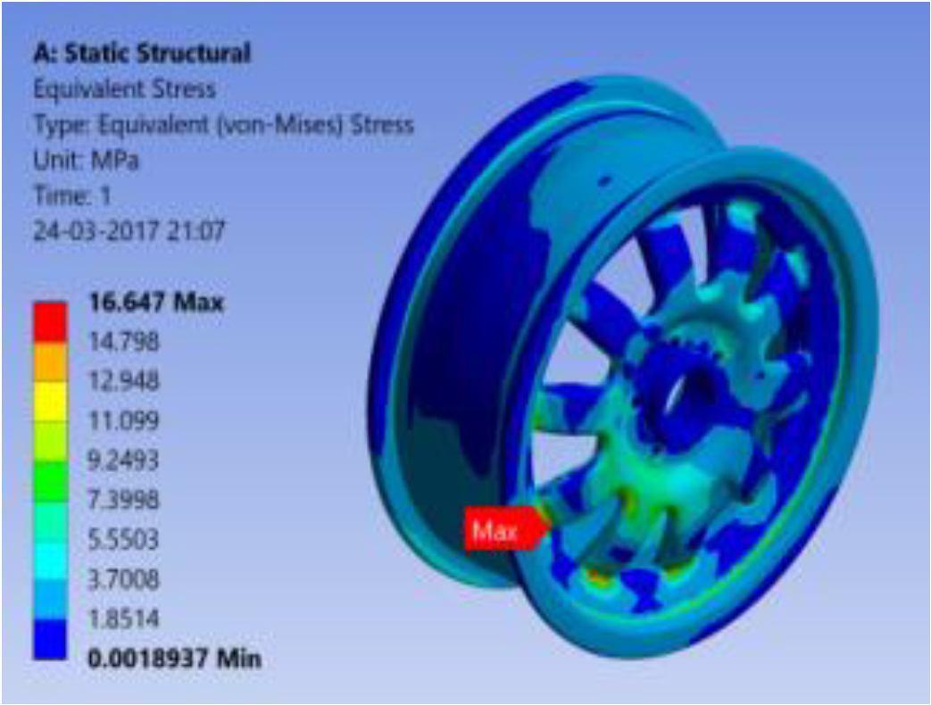

International Journal for Research in Applied Science & Engineering Technology (IJRASET) ISSN: 2321 9653; IC Value: 45.98; SJ Impact Factor: 7.538 Volume 10 Issue VIII Aug 2022 Available at www.ijraset.com 75©IJRASET: All Rights are Reserved | SJ Impact Factor 7.538 | ISRA Journal Impact Factor 7.894 | C] Equivalent Stress X. RESULTS AND COMPARISION: Analysis is done on imported design from CATIA V5 using static structural and modal analysis workbench under required condition, on different alloy and composite materials. The results are obtained and compared between different materials under same parametricPROPERTIESconditions. Aluminium alloy Magnesium alloy Titanium alloy Forged Steel Alloy Total Deformation 0.13156 mm 0.13505 mm 0.16258 mm 0.14409mm EquivalentStrainElastic 5.2416emm/mm004 5.3669emm/mm004 6.4531emm/mm004 6.9012 004 mm/mm Equivalent stress 37.147 MPa 24.104 MPa 61.827 MPa 50.302 Mpa Result and Comparision When comparing between alloy materials aluminium alloy has better deformation factors and better strain coefficients But when alloy materials is compared to composite material, composite material has better deformation and stress factors. 4) Graphical Representation of Static Analysis
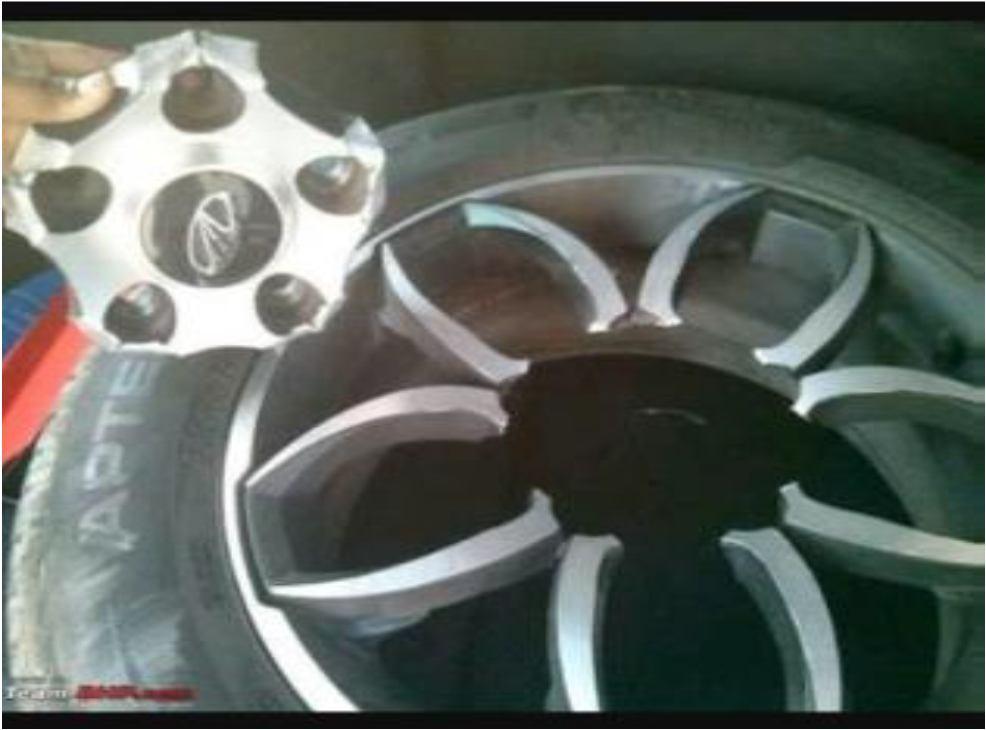
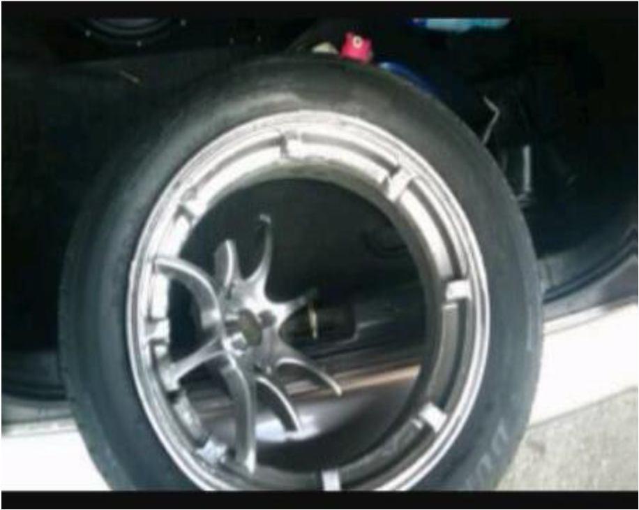
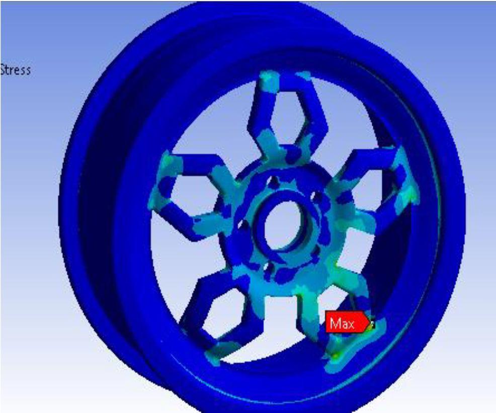
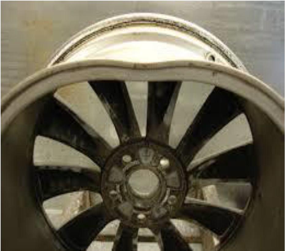
International Journal for Research in Applied Science & Engineering Technology (IJRASET) ISSN: 2321 9653; IC Value: 45.98; SJ Impact Factor: 7.538 Volume 10 Issue VIII Aug 2022 Available at www.ijraset.com 76©IJRASET: All Rights are Reserved | SJ Impact Factor 7.538 | ISRA Journal Impact Factor 7.894 | XI. PRACTICAL FAILURE CASES Comparing the theoretically most stressed areas of wheel rim (obtained from ansys software) with practical failed cases

[3] G.Ashokkumar et, al., “Design and analysis of wheel rim by using CATIA & ANSYS”. International Research Journal of Engineering and Technology (IRJET) Volume: 03 Issue: 12 | Dec 2016 e ISSN: 2395 0056 p ISSN: 2395 0072
77©IJRASET:
3) The inside bead seat reveals the greatest deflection and is concurrently prone to loss of air pressure due to dislodgment of the tire on the rim. Actually failure of alloy wheel occurs mostly at the areas where there is max stress values occur (predicted by analysis software) More deformed areas are also in agreement with theoretical values.
[1] V.Karthi et, al., “Design and analysis of alloy wheel rim” International Journal of Innovative Research in Science, Engineering and Technology An ISO 3297: 2007 Certified Organization Volume 3, Special Issue 2, April 2014.
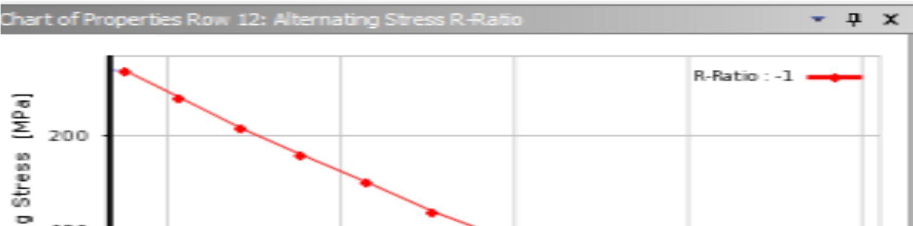
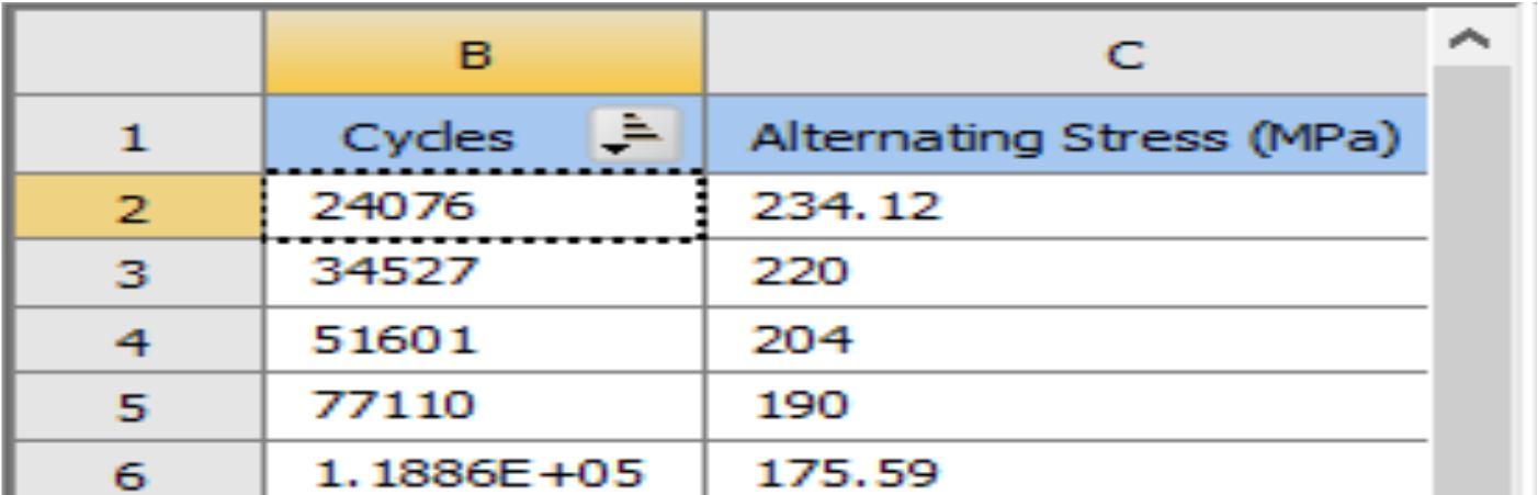
[7] M. Saran Theja, M. Vamsi Krishna, “Structural and Fatigue Analysis of Two Wheeler Lighter Weight Alloy Wheel”, IOSR Journal of Mechanical and Civil Engineering (IOSR JMCE). e ISSN: 2278 1684,p ISSN: 2320 334X, Volume 8, Issue 2 (Jul. Aug. 2013), PP 35 45.
[2] Daniel Antony C et,al., “Design and Analysis of Two Wheeler Alloy Wheel Rim Using Composite Materials”. International Journal of Innovative Research in Science, Engineering and Technology (An ISO 3297: 2007 Certified Organization) Vol. 5, Issue 5, May 2016.
| ISRA
[6] Ravi Lidoriya, SanjayChaudhary and Anil Kumar Mohopatra, “Design and Analysis of Aluminium Alloy Wheel using PEEK Material”, International Journal of Mechanical Engineering and Research. ISSN No. 2249 0019, Volume 3, Number 5 (2013), pp. 503 516.
[8] V.Karthi, N. Ramanan and J. Justin Maria Hillary, “DESIGN AND ANALYSIS OF ALLOY WHEEL RIM”, International Journal of Innovative Research in Science, Engineering and Technology. ISSN (Online): 2319 8753 ISSN (Print): 2347 6710 Volume 3, Special Issue 2, April 2014.
XII. CONCLUSIONS
ISSN: 2321 9653; IC Value: 45.98; SJ Impact Factor: 7.538 Volume 10 Issue VIII Aug 2022 Available at www.ijraset.com All Rights are Reserved | SJ Impact Factor 7.538 Journal Impact Factor 7.894 |
1) From the analysis we came to know that all the four designs are safe and are within the standard limits Among the four designs simple rim design is more promising than centrifugal rim Followed by pentagonal rim Among the four materials steel alloy is the best material followed by aluminium and magnesium occupies last position as it has more deformation for the same loading condition.
REFERENCES
[4] Gudise Venkateswarlu et, al., “Design and analysis of alloy wheel with different alloys”. International journal of advance research in science and engineering volume no 06 issue no 10, Octomber 2017.
International Journal for Research in Applied Science & Engineering Technology (IJRASET)
[5] J Stearns et, al., “performed analysis to understand the pressure and radial loads influence on stress and displacement response of rotating bodies in automobiles”. International Journal of Scientific and Research Publications, Volume 8, Issue 11, November 2018 486 ISSN 2250 3153.
2) from this results we can then why magnesium alloy material is only used for pretty shorter period restricted to racing cars only From the fatigue analysis aluminium alloy has got more life than that of the steel alloy Even though the safety factor is almost equal for both the materials aluminium is subjected to less damage compared to steel (for same loading conditions ) From the above results we define a new material (Al Mg alloy) which is more promising than other two i.e. these has got less deformations like ALUMINIUM and more life like magnesium Under the influence of a radial load, the rim tends to vocalize about the point of contact with maximum displacement occurring at the location of the bead seat.