
10 IX September 2022 https://doi.org/10.22214/ijraset.2022.46845
ISSN:

ISSN:
Ravi Thakur1 , Shrinath Kulkarni2
1Student, Department of Mechanical Engineering, Marathwada Institute of Technology, Aurangabad, India
2Assistant Professor, Department of Mechanical Engineering, Marathwada Institute of Technology, Aurangabad, India

Abstract: This paper deals with the design and manufacturing of shock absorbers for ATVs (All Terrain vehicles). For this dual rate coil spring shock absorbers, we have considered an independent type double Wishbone arrangement for required off road conditions.
The purpose of designing and manufacturing this Shock absorber is to optimize the wheel assembly and to manufacture it less expensive, light in weight, and strong as per the off road condition are addressed.
This paper summarizes the design calculation, Analysis of components of shock absorbers, and manufacturing process required for this Suspension System of an ATV.
Keywords: Shock absorbers calculations, spring calculations, Analysis of shock absorber, etc.
The main problem faced by exciting shock absorbers was that they were expensive and couldn’t be customized as per the vehicle requirement.
So, to solve this problem we decided to manufacture custom dual rate shock absorbers. The challenge we faced was finding out the proper material and manufacturing process for shock absorbers. As there were suitable materials available like chromo vanadium but that material, we must import from outside the country which could have increased the price which wasn’t matching our objective.
So that’s why we choose to go with IS4454 Grade 2 cold drawn spring material which had suitably good strength as compared with chrome vanadium.
The limitation of our shock absorber is that one can use it only for the all terrain vehicle and it has a cycle life of two years. After that, it won’t be reliable for use.
The suspension system has a spring, a damper, and dual wishbones. The energy stored by the road shock causes the springs to respond in an expansion and contraction response.
These expansions and contraction responses are restricted to a reasonable level by the damper which is more commonly called a shock absorber.
The vehicle suspension system is responsible for vehicle control, driving comfort, and safety as the suspension carries the vehicle body and transmits all the forces between the rod and the body. The springs can take any shape and form depending upon the road conditions.
The helical springs are made up of wire in the form of a helix size and are primarily intended for compression or tension loads. The cross section of wire from which the spring is made is Square and grounded type.

1) From our First reference, we got to know about the spring calculation required for designing spring.
2) From this knew how we perform damper calculations to find the force acting inside the dampers.
3) We understood how to prepare an experimental setup for the Shock absorbers and which point should be fixed and how to apply load on the setup.
4) This paper provided us with the inside layout of the hydraulic shock absorbers and helped to choose the appropriate type of shock absorber.
ISSN: 2321 9653; IC Value:

at www.ijraset.com
The shock absorber is an important part of automotive that influences ride characteristics such as ride comfort and driving safety. There are different kinds of automotive shock dampers such as moment sensitive damping, acceleration sensitive damping, and continuous damping control. The displacement & movement shock absorber has a similar structure compared to the conventional passive shock absorber. Damping qualities of automobiles can be analysed by considering the performance of displacement & movement sensitivity shock absorbers for ride comfort.
Vibration dampers are arranged parallel to the vehicle suspension and have the following tasks: to dampen vibrations of the vehicle’s body caused by uneven roads or driving conditions and to quickly reduce and eliminate the road induced wheel and axle vibration to provide constant contact between the tire and the roadway.
The shock absorbers are one of the fundamental elements of a vehicle suspension system. Its function is to stop spring oscillation providing control, grip, stability, and control to the occupant of the vehicle. The shock absorber is a hydraulic device that works with mainly two types:
Monotube hydraulic shocks
Twin tube hydraulic shocks
ISSN: 2321 9653; IC Value: 45.98; SJ Impact Factor: 7.538
10 Issue IX Sep 2022 Available at www.ijraset.com
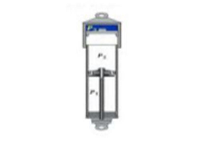
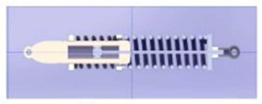
Fig. 4.1:
a Mono Tube Damper [4]
So, choose a monotube shock absorber over a twin tube shock absorber as per the given suitable condition for off road which is as follows:
1) As temperature increases, oil can release heat with less effort.
2) Zero restrictions on installation angles.
3) Larger oil capacity and greater heat dissipation allow for a stable damping force that is continuous.
4) 100% efficiency overall temps.
5) The piston valve is bigger and wider in a mono tube design which allows for a wider area of pressure. In return, this means that the shock can create even a subtle dampening force precisely.
1) Shock Absorber Fluid Study: [4] Damper oil is usually a selected light mineral oil, sometimes instead of synthetic oil which is more expensive but may have reduced variation of viscosity with temperature. The usual mineral oil contains sulfurized compounds, giving it a persistent noxious scent. So, as per the given condition, we choose Sasol 57 oil and nitrogen gas of 25 30 bar pressure for a quick rebound for our shock absorber. The properties of the damping fluid, normally a mineral oil with some additives, can be classified under several headings, mainly chemical, mechanical, thermal, and other.
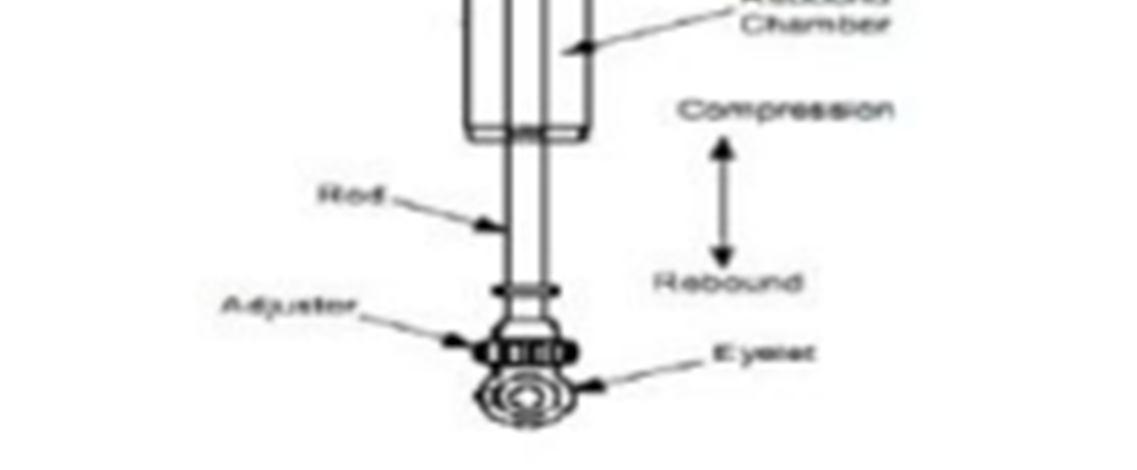
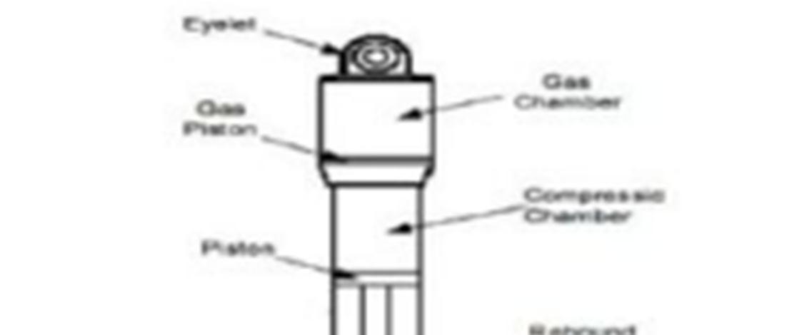
2) Material Selection: For manufacturing shock absorbers, we have used alloy steel material. As it is easily available in the market and easy to manufacture. The floating piston is made up of plastic material. The monotube shock absorber has two compartments, one section is for oil and another for nitrogen chamber and it is separated by a floating piston.
3) Calculations
Fig
(IJRASET
ISSN: 2321 9653; IC Value: 45.98; SJ Impact Factor: 7.538 Volume 10 Issue IX Sep 2022 Available at www.ijraset.com
[2] = 14 mm = 25 mm
Pressure on the rod: = pressure * area = ( ∗ 2 /4) = ( ∗ 1424) = 153.93 2 = ( / ) = (25 ∗ 9.81153.93) = 1.5932 N/ 2
The pressure of piston: = ( ∗ 2/4) = ( ∗ 2524) = 490.87 2 = ( / ) = (94.5 / 9.81490.87) = 1.8885 N/ 2
Pressure during rebound: = = 490.87 153.93 = 336.94 2 = ( 1− 2) * = (1.88− 1.59) * 336.94 = 70.75 N Gas pressure: = * = 25 * 153.93 = 3848.25 N
The purpose of a spring is to cushion, absorb, or controlling of energy arising due to shock and vibration. It is also used for control of motion, storing energy, and measuring forces.
So, we are using two springs in series. The biggest advantage of a coil over style shock absorber is as follows. The machined component design makes them easily adjustable, replaceable, and tuneable. The ability to fit a wide variety of coil spring rates and sizes makes them ideal for both supporting the vehicle’s weight and absorbing the inconsistencies on the road. Also, you can properly tune as per your coils and shock tuning is concerned to give you the utmost performance out of your suspension.
The dual rate coil spring provides variable spring rates, which can be used to improve traction and handling in off road conditions.
International Journal for Research in Applied Science & Engineering Technology (IJRASET)
ISSN: 2321 9653; IC Value: 45.98; SJ Impact Factor: 7.538 Volume 10 Issue IX Sep 2022 Available at www.ijraset.com
There are given below following materials that can be used for off road vehicle shock absorbers. Mainly the good and highly chosen material for springs is chromo vanadium ASTM A231 because of its high strength and shock absorbing capacity go with IS4454 cold drawn spring steel which has moderate qualities as compared to chromo vanadium material.
Characteristics of cold drawn steel IS4454 grade 2: Min. tensile strength=1290 Mpa
Modulus of rigidity (G) = 73000 Mpa FOS=1.5 Tensile strength=1290 N/mm
Shear stress=0.6*1290=774/FOS =516 N/mm Required travel of spring front = 4 inches
[1] Force, P = 2100 N
Wahl’s Stress factor (K) = K = ((4 −1/4 −4) (0.615/ )) = 1.23
Shear stress ( ) = = K (8 ∗ ∗ / ∗ 2) 2 = (8 ∗ ∗ / ∗ ) d = 9 mm
Diameter of Wire coil = 9mm
Diameter of spring, D D = Cd = 59 mm
Deflection of the spring, = (8 ∗ ∗ D3 ∗ / ∗ 4) N = ( ∗ 4 ∗ 8 ∗ ∗ 3 ∗ ) = 9
Total no. coil, = N + 2 = 11
Solid length = * d = 99 mm
Actual deflection of the spring, = (8 ∗ ∗ D3 ∗ / ∗ 4) = 64.83 mm
Gap = ( −1) ∗ 2 = 20 Free length = Solid length + + Gap Free length = 183.83 mm
The pitch of coil = ( ℎ / −1) =18.38 mm Spring rate, 1 = ( ) = 39.37 N/mm Actual spring rate, 1 1 = ( ∗ 4 /8 ∗ D3 ∗ ) = 40.36 N/mm
[1] Force, P = 1500 N
Wahl’s Stress factor (K) = K = ((4 −1/4 −4) (0.615/ )) = 1.208
Shear stress ( ) = = K (8 ∗ ∗ / ∗ 2)
2 = (8 ∗ ∗ / ∗ ) d = 8 mm
International Journal for Research in Applied Science & Engineering Technology (IJRASET)
ISSN: 2321 9653; IC Value: 45.98; SJ Impact Factor: 7.538 Volume 10 Issue IX Sep 2022 Available at www.ijraset.com
Diameter of Wire coil = 9mm
Diameter of spring, D D = Cd = 57 mm
Deflection of the spring, = (8 ∗ ∗ D3 ∗ / ∗ 4)
N = ( ∗ 4 ∗ 8 ∗ ∗ 3 ∗ ) = 9
Total no. coil, = N + 2 = 7
Solid length = * d = 56 mm
Actual deflection of the spring, = (8 ∗ ∗ D3 ∗ / ∗ 4) = 37.16 mm
Gap = ( −1) ∗ 2 = 12
Free length = Solid length + + Gap Free length = 105.16 mm
The pitch of coil = ( ℎ / −1) =17.52 mm
Spring rate, 1 = ( ) = 39.37 N/mm
Actual spring rate, 1 1 = ( ∗ 4 / 8 ∗ D3 ∗ ) = 40.36 N/mm
3) Calculations to check to buckle of Primary spring
[5] K = ( ∗ / 8 ∗ 3 ∗ ) N = ( ∗ 8 ∗ 3 ∗ ) = 9 Pitch = 18.38 mm
Checking torsional shear stress Considering static failure Let static shear stress factor, = 1 + (0.5 / ) = 1.076
Static shear stress, = (8 ∗ ∗ / ∗ 3) = 465.68 N/mm
By considering the curvature effect, = ((4 −1/4 −4) (0.615/ )) = 1.23
The shear stress induced by the curve effect is given by. = (8 ∗ ∗ / ∗ 3) = 532.33 N/mm
Check for buckling of the two ends of the fixed spring ( ) ≤ 5.2 3.55 ≤ 5.2 So, the bucking will not occur this spring.
4) Calculations to check to buckle of Secondary spring
[5] K = ( ∗ / 8 ∗ 3 ∗ )
N = ( ∗ 8 ∗ 3 ∗ ) = 8
Pitch = 17.52 mm
Checking torsional shear stress considering static failure Let static shear stress factor, = 1 + (0.5 / ) = 1.070
Static shear stress, = (8 ∗ ∗ / ∗ 3) = 56.83 N/mm
By considering the curvature effect, = = ((4 −1/4 −4) (0.615/ )) = 1.208
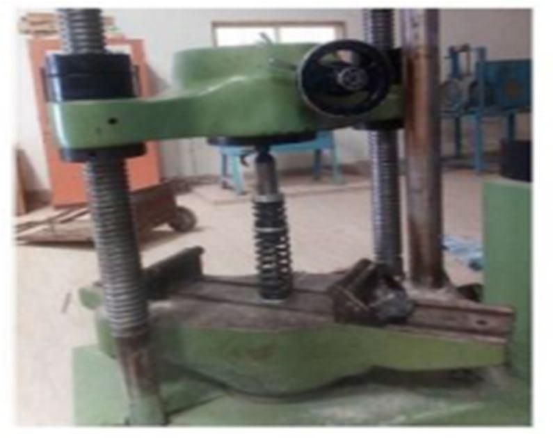
We have done two major processes while manufacturing that
ISSN: 2321 9653; IC Value: 45.98;
Issue
Sep 2022
Impact Factor:
at www.ijraset.com
winding machine and finishing process of springs.
Fig
spring got manufactured
1) Winding Machine Process: To start with spring manufacturing, you must have a winding machine. A winding machine is a machine that will pull your wire around and make it coil up into a spring shape. What kind of winding machine you'll need depends on what size wire you'll be working with, and, how many springs you want to make
2) Finishing Process: After coiling your springs and forming the ends, you will need to get rid of the stress that folding the wire has caused. To do this, an oven is needed. Your oven temperature depends on what material you use for your spring.
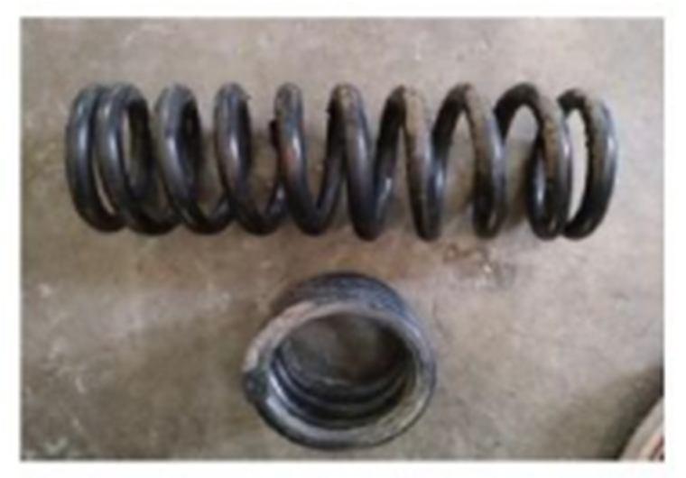
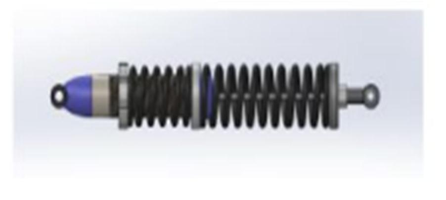
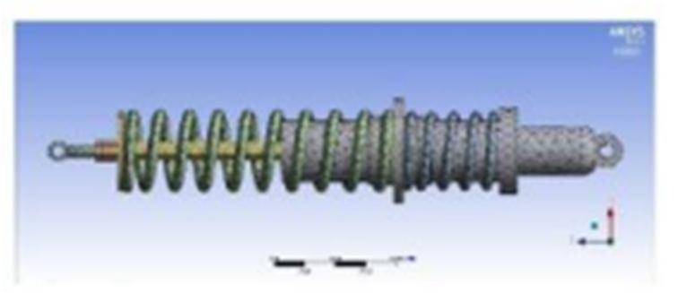
Fig 5.2:
view of shock absorbers
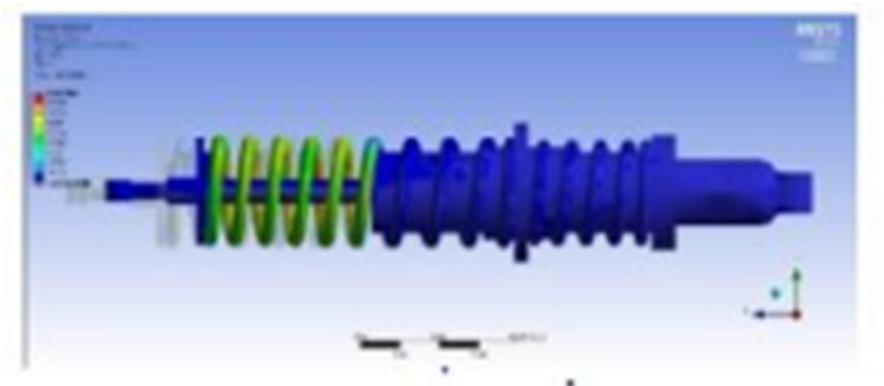
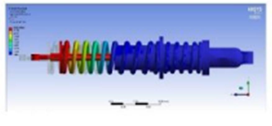
The Designing has been done in Solid works software and its finite element analysis has been done in Ansys software. The analysis has been done by considering off road condition forces to test the factor of safety in the worst situation during bumps. The shock absorber mounting points were constrained and force was applied at the bottom of the shock absorber as per the actual vehicle working scenario.
International Journal for Research in Applied Science & Engineering Technology (IJRASET)
ISSN: 2321 9653; IC Value: 45.98; SJ Impact Factor: 7.538
Volume 10 Issue IX Sep 2022 Available at www.ijraset.com
In ATV shock absorbers deal with unexpected situations like road shocks, bumps, etc. so, the basic point of designing and manufacturing this was as follows:
1) Provides great articulation to the vehicle • It is comfortable in complicated road conditions.
2) Variable spring rate improves traction and handling of the vehicle As compared to other commercial stiff and expensive shock absorbers this is leak proof at a high damping, soft while bumps and easily manufactured at low cost. And we also proved that our shock absorber didn’t get any breakage at the universal testing machine as well as during the FEA test. So, we conclude that this experiment of designing and manufacturing custom shock absorbers is successful and can be used for all terrain vehicles.
[1] V. B. Bhandari, Design of Machine Element, 2nd Edition, Tata McGraw Hill Company, 5th Print, (2008) 389 439.
[2] International Journal of Engineering Research (ISSN: 2319 6890) Volume No.2, Issue No. 7, 01 Nov 2013 Mathematical Modeling of an Automobile Damper N. B. Kate, T. A. Jadhav
[3] 2nd International Conference on Materials Manufacturing and Design Engineering Optimization of Three Wheeler Front Suspension Coil Spring H. B. Pawara, D. D. Desalea
[4] John Dixon, The Shock Absorber Handbook, John Wiley & Sons, 2008
[5] Dynamic Analysis of the Front and Rear Suspension System of an All Terrain Vehicle Khan Noor Mohammad, Vatsal Singh, Nihar Ranjan Das, Prajwal Nayak, B.R. Patil, 2018
[6] Talbott, M, and Starkey, J An Experimentally Validated Physical Model of a High Performance Mono Tube Damper SAE Technical Paper Published.
[7] Nitin S. Gokhale, Sanjay S. Deshpande, Dr. Anand N. Thite, Practical Finite Element Analysis reference book 2008.
[8] Mohd Izaham Zainal Abidin, Jamaluddin Mahmud, Mohd Juzaila Abd Latif, Aidah Jumahat, Experimental and Numerical Investigation of SUP12 Steel Coil Spring, The Malaysian International Tribology Conference, (2013) 251 257
[9] Harshad B. Pawar, Amol R. Patil, Dr. Sanjay B. Zope, Design and Analysis of a Front Suspension Coil Spring for Three Wheeler Vehicle, International Journal of Innovations in Engineering Research and Technology, (2016)
[10] Simms, A., and Crolla, D., The Influence of Damper Properties on Vehicle Dynamic Behaviour Technical research paper.
