
ISSN: 2321 9653; IC Value: 45.98; SJ Impact Factor: 7.538

Issue
Sep
at www.ijraset.com


ISSN: 2321 9653; IC Value: 45.98; SJ Impact Factor: 7.538

Issue
Sep
at www.ijraset.com
Rohini J P1, Chandasree Das2, B Dhandapani3
2, 3Dept of EEE, BMSCE Bengaluru
Abstract: DC DC Converters are the inevitable stage in a system to power up an electronic device, as it is very prominent to obtain a regulated and constant dc-dc supply to most of the electronic devices. These dc-dc converters are supplied with the dc supply either given directly by dc sources like batteries or obtained by converting AC to DC supply. In the proposed project, firstly the single phase ac supply of 230V,50 Hz is boosted to 390V DC and concurrently the power factor of the supply is corrected in the Boost Power Factor Correction (PFC) stage using IC UCC28180 which constitutes the first stage of the project. Further, this DC voltage is given to the Forward converter where it is stepped down to 48V DC which is finally given to power up the ventilator. The designing of both Boost and Forward converters is done and they are verified by simulating them in the MATLAB Simulink software platform. Hardware implementation with the designed values is done and the relevant waveforms are obtained.
Keywords: DC DC Converter, Forward Converter, Boost PFC Converter, Ventilator, Switched mode power supply, UCC28180.
In the recent decades, almost all the applications in the physical world known to humankind consists of electronic devices in any one or more stages of the applications like ignition system in cars, electronic devices medicine field, in space applications, automatic cameras, washing machines and other numerous domestic applications [1]. Due to their multitude of applications, it is very prominent to maintain their reliability and regulation. As all the electronic devices need DC supply as their energy source, it is crucial to supply resilient, regulated and highly efficient DC power to them [2] Based on the application that is considered, the DC DC Converter is chosen upon considering the output ripple, efficiency, stable operation (i.e., it has to be reliable even upon hindrances like abnormal switching operations, over voltage, under voltage, system burn out, desired output power ratings (voltage and current ratings), etc.[3]
A mechanical ventilator, also called as a respirator, is a medical electronic machine that assists breathing which is primarily used in ambulances and Hospitals.
Ventilators help people breathe easier, they are generally used for the fleeting periods of time, for example, during surgery when a patient is under anesthesia. Though large mechanical ventilators are found in a hospital setting, there are also smaller, more portable versions that can be used in the home and in ambulances.
Simply put, a ventilator removes carbon dioxide from the body and provides oxygen to support breathing. They use positive pressure to blow oxygen, or a mixture of gases, into the patient's airways and lungs. They can also carry carbon dioxide or exhale to the patient. The ventilator usually consists of the breathing tube and the ventilator itself. They may also include compressors, humidifiers, and heaters.
The power supply plays an important role in the function of the mechanical fan. Fans usually get their energy from electricity or compressed air. Power can come from a wall outlet at 100 200VAC at 50/60Hz, or from a 10 30V DC battery. Batteries are commonly used to power ventilators used for home care and transportation. If compressed air is used for power, it usually comes from hospital tanks or intakes.
The figure 1 below shows the block diagram of the proposed project. It consists of 3 stages namely as rectification, boost converter and the forward converter stage. The 230V, 50Hz AC supply is first rectified to 325V DC which is then given to the Boost PFC converter, which boosts it to 390V and finally this 390 V is step downed to get 48V, 6A DC power which is fed as the DC power supply to the mechanical ventilator.

Science
Engineering Technology (IJRASET

ISSN: 2321 9653; IC Value: 45.98; SJ Impact Factor: 7.538
10 Issue IX Sep 2022 Available at www.ijraset.com
A rectifier is a device which is used to convert the alternating current (AC) of certain frequency to the desired Direct Current (DC) , which is obtained by periodically reversing the direction to obtain DC in only one direction. This phenomenon is called as “Rectification” as it straightens the current direction. The Rectifier is the first block of the proposed project, which converts the 230V, 50Hz single phase AC supply from the wall socket to the DC power of 325V. This obtained 325V DC voltage is further given to the Boost PFC Block.
The Rectifier Circuits can either be single phase or Multi phase. The majority or almost all the Domestic pieces of equipment use low power rectifiers, hence they are of Single Phase, whereas for Industrial applications Multi Phase rectifiers are required even in the power transmission in the HVDC systems.
A Full Wave rectifier is an electronic circuit, which converts the whole input waveform i.e, both negative and positive parts into one constant polarity as its output. Mathematically, it will correspond to an absolute value function. In the end, this rectification leads to obtaining pulsating DC and yields to a higher average output value. The circuit requires four diodes in a bridge configuration with an AC source or two diodes with a Centre Tapped transformer.

ideal single phase full wave rectifier should produce the following average and RMS no load output voltages
PFC Boost converter is one of the commonly used device to obtain the improvised power factor. Power Factor Correction is the technique to rectify the unwanted effects of the electric loads which pose a power factor of less than one. When the power factor is less than one then the apparent power delivered to the load will be comparatively greater than the real power supplied to the load. The main aim to incorporate the PFC circuit is to bring the input current waveform in phase with the input voltage waveform. There are several techniques to attain this active power factor correction. They are divided into “active “ and “passive”. In the passive type in addition to the diode bridge rectifier circuit “passive” components are used. Even though this PFC technique helps in attaining desired current waveform, the voltage is not regulated. Whereas in the “active” PFC technique this hindrance can be overcome by using the active switches in conjunction with the reactive elements. Further, this active PFC is categorized into two types based on the switching frequency, as “lower frequency” active PFC where the at the low order harmonic the switching takes place henceforth synchronizing with the line voltage, while in the “ high frequency”, switching takes place at a relatively higher frequency than the line frequency.
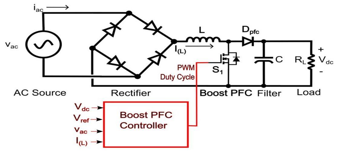
1) Control Strategy: The working of the Boost PFC Converter using the IC UCC28180 is discussed as follows: The 230V, 50Hz AC supply voltage is rectified and given to the Boost topology. The circuit consists of a power MOSFET, power diodes, inductors, and bulk capacitors. The DC output voltage across the bulk capacitor set is sensed by Error Amplifier 2 with the pre determined reference voltage. This error voltage from the amplifier is then fed to the multiplier and multiplied with the template sinusoidal input voltage to get the reference current, (reference). The error ( that is the output of Error Amp 1, as the difference of ( (actual) and ( (reference) provides the correct timing logic for the switching driver circuit to turn on and turn off the MOSFET in the Boost converter. Hence, the continuous conduction of current flow for the full cycle of the input voltage is guaranteed by this method. The feedback control or the closed loop operation of the proposed project is done by using the Texas Instruments IC UCC28180.

Science & Engineering Technology (IJRASET

ISSN: 2321 9653; IC Value: 45.98; SJ Impact Factor: 7.538
10 Issue IX Sep 2022 Available at www.ijraset.com
Fig 2(b) shows the circuit diagram of the
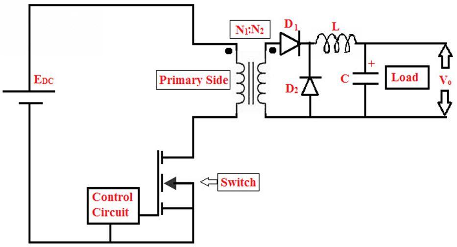
converter which
developed in this proposed project, figure 2 (b) shows the open loop diagram of the converter, whereas the closed loop control of the converter is done by using the Texas instruments IC UC3842 along with the photodiode TL431. The purpose of the Forward converter in this project is to step down the voltage from 390 V to 48V which is then supplied to the ventilator. The forward converter is chosen upon considering that it is an isolated dc dc converter that provides the required electrical isolation in the system as well as due to its advantages when considered to other isolated converters.

( is the input to the forward converter, which is 390V DC, and the output is Vo which is 48V which is obtained at the output side of the converter. The circuit consists of 2 diodes, an inductor, a 2 winding transformer capacitor (some extra bank of capacitors for smoothening) , and a MOSFET switch.
Fig.2(a) and fig.2(b) PFC Boost Converter and Forward Converter respectively.
9653;
www.ijraset.com


2321 9653; IC Value: 45.98; SJ Impact Factor: 7.538

10 Issue IX Sep 2022
at www.ijraset.com
the core[5][6].
is equal to 1 MΩ, and is a constant that is equal
Data: Input Voltage, =390V
Voltage, =48V
Voltage ripple =1%
Current ripple =10% Switching Freq, =25kHz
1.
results in a maximum duty ratio of 0.5 for the switch. For margin, let D = 0.35.[7]
N
N
= 3
a 1 percent output voltage ripple,
% = (0.01)

= 0.48V
output current ripple,
=0.1(6)=0.6 A
capacitor size is determined by assuming that the
produced primarily by the equivalent series resistance[8], or
=4.8/48=0.1
ISSN: 2321 9653; IC Value: 45.98; SJ Impact Factor: 7.538 Volume 10 Issue IX Sep 2022 Available at www.ijraset.com

In this, power supply 230V is stepped down to 48V, 6A by using two DC/DC converters. DC DC converter converts a source of DC voltage to DC step up or step down voltage. Initially 230V Single phase AC is rectified to 325V DC by using single phase full bridge rectifier, which is then boosted to 390V regulated DC using PFC boost converter. Then again it is stepped down to 48V using forward dc/dc converter.
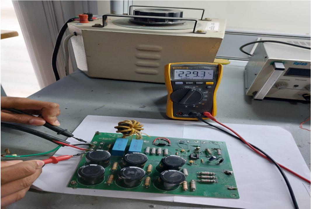
The fig. 3(a) shows the top view of the Boost PFC converter set up with the UCC28180 board. The input of 230V, 50Hz AC is given to the board from the auto transformer by varying the variac to 230V AC and the given input is measured at the input terminals with the help of multimeter by setting it to AC mode and it is seen to be 229.3V AC as shown in the fig.3(a).
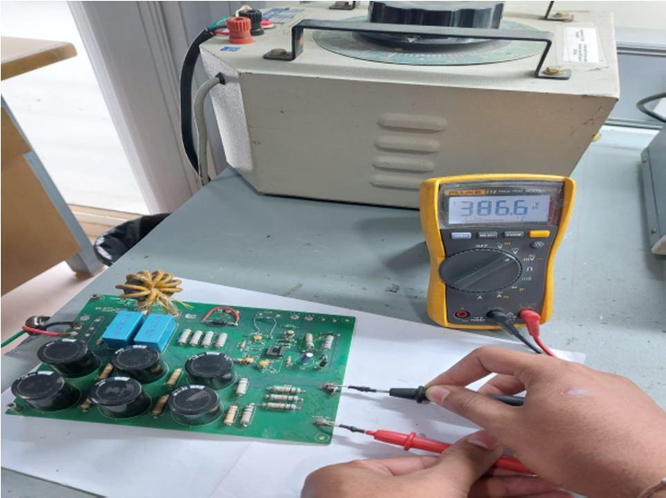
The fig.3(b) shows the top view of PFC Boost converter when it’s output is measured at the output terminals by using the multimeter setting it to DC mode and it is found out to be 386.6V DC.
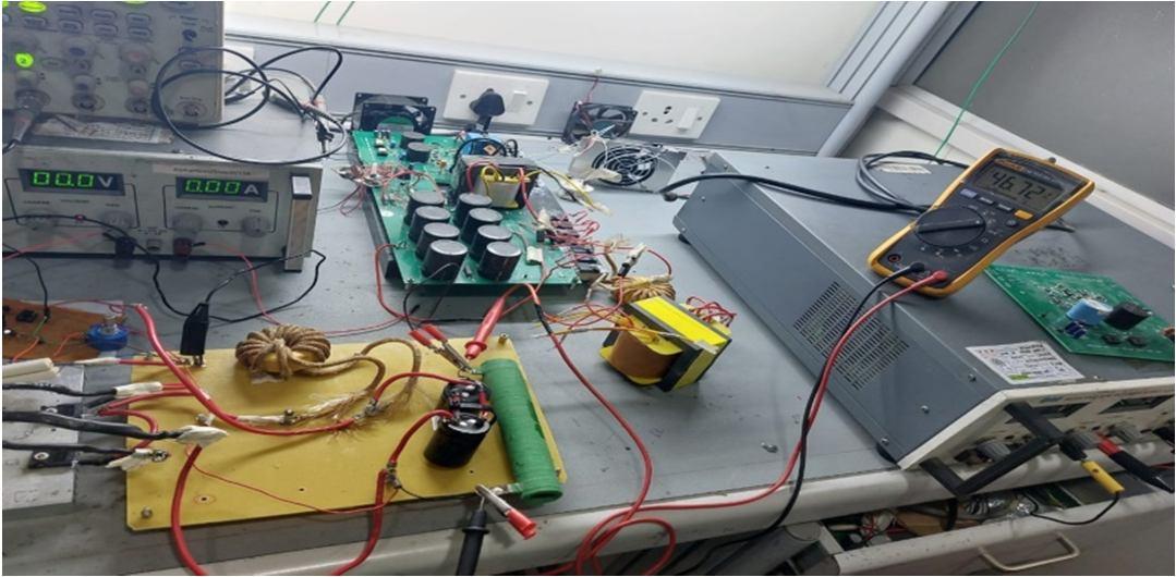
The Fig.4(a) shows the output of the forward converter obtained, which is measured by the multimeter at the output terminals of the forward converter and the output is found to be 46.72V DC which is almost equal to the desired value of 48V DC
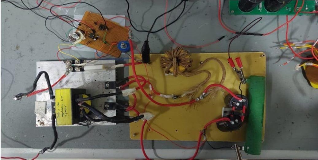
The Fig.4(b) shows the top view of the forward converter set up with the closed loop control attained by using IC UC3842.

1) No Load Condition: The Table 3 shows the DC voltage values obtained by varying the input voltage from 10 to 260V, 50Hz AC in the Boost PFC converter set up under No load condition. It is seen that the output voltage is linear to the input voltage till 40V of input and after that it is seen to be constant with the value of 391.4V DC
(IJRASET
ISSN: 2321 9653; IC Value: 45.98; SJ Impact Factor: 7.538

10 Issue IX Sep 2022 Available at www.ijraset.com
TABLE 3
No Load
14.5
27.1
40.2
52.5
391.4
391.4
391.4
391.4
391.4
391.4
391.4
391.4
391.4

Load
14.5
27.1
52.5
390.4
390.4
390.4
390.4
390.4
390.4
4
2321 9653;
Value:
at www.ijraset.com

19.67

36.36
38.6
41.5
44.6
45.7
48.6
shown
a cathode
of
(CRO)
ISSN: 2321 9653;
at www.ijraset.com

The Fig.6 shows the waveforms of the rectifier board with the input of 230V, 50Hz AC, and the output of 325V DC. It shows that the input is 230V,50Hz AC sinusoidal voltage waveform with no ripple which is denoted as and the output is 325V regulated DC voltage which is denoted as which is obtained by the full bridge rectifier circuit.


The Fig.7.shows the waveforms of the Boost PFC converter with the input of 325V DC and the boosted output of 390V DC. The straight line is the input given to the boost converter which is 325V DC denoted as in fig.7 and the triangular waveform denoted as is the output of the boost converter obtained which is 390V DC with a ripple of 1%.

ISSN: 2321 9653; IC Value: 45.98; SJ Impact Factor: 7.538

Volume 10 Issue IX Sep 2022 Available at www.ijraset.com
The Fig.8 shows the output waveform of the forward converter, which is seen to be 48V DC. It shows the output voltage waveform of the forward converter denoted as which has the obtained value of 48V DC under a full load condition with a load of 8Ω resistor, with some ripple due to the losses in the MOSFET switches used

The designing and development of Power Supply for Ventilator is done through UPS system. The designing of various components is done according to the Texas Instruments Standards and the obtained values are verified by simulating the circuit in the MATLAB Software. In the proposed system, the DC power supply of 48V is designed for the Mechanical Ventilator by implementing Forward converter along with Boost PFC converter Circuit. Both the converters are closed loop controlled in order to get the required constant output voltage.
The filtering is done using low pass filter for filtering the dc input fluctuations. Feedback is taken from the converter output and fed to the PID controller and PID Controller is used for controlling output voltage using proportional, Integral and derivative values and accordingly the PWM waveforms are generated for the output voltage.


The Hardware Implementation of the proposed system is done and the practical outputs of the PFC Block and Forward Converter block and theoretical values are verified.

International Journal
Science & Engineering Technology (IJRASET)

ISSN: 2321 9653; IC Value: 45.98; SJ Impact Factor: 7.538

Volume 10 Issue IX Sep 2022 Available at www.ijraset.com
Authors are thankful to the Management, BMS Educational Trust, Principal and Vice Principal, BMS College of Engineering and Alpha Design Technologies Pvt. Ltd. for their continuous support
[1] Https://eepower.com/technical articles/dc dc converter applications/#
[2] Fang lin luo and hong ye, advanced dc/dc converters, crc press llc, 2003
[3] y. Belopolsky;r. Dassatti, “Hybrid technologies for high frequency switching power supplies”, 1991 proceedings 41st electronic components & technology conference
[4] Https://www.ti.com/product/UCC28180#features
[5] S. Sankar;M. Padmarasan;T. Raghavi;Srishtisinha;S. Saravana Kumar, “Simulation and design of closed loop controlled PFC Boost Converter with EMI Filter”, 2013 7th International Conference on Intelligent Systems and Control (ISCO)
[6] Gitanjali Anand;Shri S. K. Singh, “Design of single stage integrated bridgeless boost PFC converter”, 2014 International Conference on Medical Imaging, m Health and Emerging Communication Systems (medcom)
[7] Shin Ju Chen;Sung Pei Yang;Meng Fu Cho, “Analysis and design of an interleaved series input parallel output ZVS forward converter”, 2009 International Conference on Power Electronics and Drive Systems (PEDS)
[8] “Power electronics circuits, applications and design”, Text book ,second edition, Ned Mohan.
