https://doi.org/10.22214/ijraset.2023.49522

11 III
2023
March
ISSN: 2321-9653; IC Value: 45.98; SJ Impact Factor: 7.538

Volume 11 Issue III Mar 2023- Available at www.ijraset.com

https://doi.org/10.22214/ijraset.2023.49522
ISSN: 2321-9653; IC Value: 45.98; SJ Impact Factor: 7.538
Volume 11 Issue III Mar 2023- Available at www.ijraset.com
Dr. Manjunath B T1 , Hineeth Kumar SP2
1,
2Department of Mechanical Engineering, Dayananda Sagar College of Engineering, Bangalore, IndiaAbstract: The leaf spring's purpose is to stabilize the vehicle because it’s an essentially required element for the suspension systems and assists in supporting the entire load on the vehicle. Hence, the design and analysis of leaf springs are the main focus of this study. To that aim, the CATIA V5 software is used to construct the model, and Ansys Workbench is used to perform static structural analysis. First, the solution is verified using the analytical method and the finite element analysis for structural steel, and then the static structural analysis of structural steel and composite material (CFRP) is compared for the same design. Here, we find that the deformation and stress values of the Composite material are less than that of structural steel.
Keywords: Design, FE analysis, Leaf spring, composite material.
In thepresent scenario, most industries, such as aerospace, and defence, are focusing on vital weight components,comfortable driving characteristics, and gasoline economy inside the vehicle. Because the weight of the fabric affects vehicle manoeuvrability, braking pressure to stop the vehicle, and tire cost. The lower the load, the less braking pressure at the brake pads. One of the capacity objects to reduce the 10% -20% up sprung weight is the suspension leaf spring. The leaf spring within the vehicle can absorb vertical absorptions, the effect of weight irregularities, and brake torque generation of composite substances to upgrades within the suspension system. [1] Erol Sancaktar, Mathieu Gratton Issued on March 1999.This paper provides and understands the manufacturing, capability and uses of Composite leaf spring produce by an epoxy resin for lightweight vehicles as weight is concerned. Results says that the blades' interior surfaces have rubber cushions to prevent the springs from bottoming out. In the case that the suspension deflects completely, this will lessen the impact load that is passed to the chassis.[2] Nishant Varma, Ravi Ahuja, T Vijaykumar, C Kannan Issued October 2020 This paper tells thatit devises to take up, hold, and discharge energy. By switching out metallic leaf springs for composite leaf springs, a significant amount of sprung and weight is typically reduced to enhance ride comfort. Results indicate that the composite leaf spring's inherent frequency is 93% higher than that of steel. Due of its significant damping qualities, the inclusion of flax between carbon fibres increased the FOS and strain energy.[3] Guang Cheng, Kaiyauan Chen, and Ynanchang Chen were issued on 10 December 2021.In this theydiscovered a failure. A phenomenon in whichthe companion leaf spring of a two specified spring had a fatigue fracture. The findings demonstrate that rubber pads were placed between the two leaves to prevent a 2-leaf spring fatigue fracture from failing. [4] Chen Qian, Wenknshi, Zhiyong Chen Shixiang, Yang Qianqian Song Issued on February 2017. This article discusses how fatigue-law interference of a composite spring's parabola is verified by fatigue-bench tests. Utilizing the suggested ply scheme design procedure frequently increases the fatigue lifetime of composite leaf springs.[5] Keerthi vasan
S.M shibi C. K Tamilselvan was Issued on 30 May 2019. This tells us about the way that reduces the load of the leaf spring using Composite materials using Epoxy, Glass carbon and aramid fibres Tests are done like flexural, tensile, and hardness tests. While we compare the test results, we conclude that tumbler, carbon, and aramid fiber spring can give more Specific strength than carbon and optical fibre springs.[6] Pulkit Solanki, AjayKumar KavitiIssued on 2018. This tells us about achieving the modification of the planning parameters like span-length and camber’s Length & Ratio. So, the results say that the work concluded that the length of span spring under th identical semielliptical springs produces max deformation and max stresses rather than the parabola leaf spring under the applied and same constraints.[7] K. Ashwini C.V. Mohan Rao Issued on 24 March 2018. This is intended to be a thorough resource for building a leaf spring utilising a variety of composites, as the automotive industry has expressed a strong interest in switching from steel to a composite spring. Conclusion: Composite leaf springsare superior to traditional mono and multisteel leaf springs in terms of weight, stresses, vibration, increasing strength, fatigue resistance, and ride comfort.
ISSN: 2321-9653; IC Value: 45.98; SJ Impact Factor: 7.538
Volume 11 Issue III Mar 2023- Available at www.ijraset.com
The current steel spring used in automobiles can be replaced with composites, which provide a bright future and are effective. [8] J.J. Fuentes H.J. Aguilar, J.A.Rodriguez b E.J. Herrera Issued on 4 March 2008. According to this report, researchers are looking into the causes of leaf springs' premature breakage in buses in Venezuela. To this goal, standard failure analysis techniques were applied, such as reviewing the spring history, visually inspecting cracked specimens, characterising different attributes, and performing simulation testing on actual components. It has been shown that the centre hole, which experienced the highest amounts of tensile stress, served as the origin of the mechanical fatigue process that caused the fracture. Failure has been made easier by a combination of problematic design, subpar materials, and problematic fabrication. It is recommended to take preventative actions to extend theuseful life of leaf springs.[9] K.S. AshraffAli D. Joseph Manuel M. Balamurugan M. Sangili Murugan Issued on 5 August 2020. This study describes the exploration and modelling of a composite spring made from polymers reinforced with glass fibre. Utilizing polymer reinforced with glass fibre, the composite spring's design and research were developed. Stresses, strains, and displacement are the modelling restrictions. Indistinguishable measures from conventional springs are used to create a highlighted in this section spring using E-Glass/Epoxy unidirectional coverings. The spring is intendedto provide the vehicle's total mass with the appropriate strength and effectiveness. As a result, the materials may be epoxy strengthened with fibreglass, which increases their effectiveness by enabling them to support enormous weights without failing. Consequently, the spring's effective design and appropriate material are created, and numerous analyses are carried out.[10] Stephan Krall, Richard Zemann Issued on 24 February 2015. These speaktohow CFRP leaf springs behave dynamically. Theinquirymakes use of experimental modalanalysis. As a result, two different techniques (likely determine and shaker test) are used to excite the parts. As an example, a standard steel spring is employed. The analytical calculation reveals that the CFRP spring are frequently approximated as a homogenous body with a constant young's modulus. The Euler-Bernoulli beam theory can be used to optimise the design of simple composite structures.[11] Birhan Alemu Tadesse, O.Fatoba Issued on January 2022. We all know that steel leaf springs have been used for years to suspend cars, but this hasn't stopped the issue of emissions and fuel efficiency in cars from being one of the downsides in the automation sector. This issue is resolved by switching from steel leaf springs to composite leaf springs. The von-Misses stress and on how values are compared between steel and composite material, and we can see that the leaf spring spring is much better than the leaf springbecause the results show that all composite materials displayed reduced weight when compared to conventional steel. [12] Donghui LI, Zhenwei FAN, Yewei ZHANG; Jian ZANG, Eengtian YANG Issued on 10 June 2020. The two-stage optimization of the leaf spring undercarriage with glass fibre components, the ground loads are determined in accordance with the that it constraints are relaxed, and the optimal control results are compared to those utilizing stiffness constraints. The composite leaf spring undercarriage of an electric aircraft is optimised with power flowability as restrictions and terms of structural weight as an objective. The results show that the optimized suspension meets the required strength and that the composite leaf landing gear utilizing the two-stage optimization technique achieves the goal of weight reduction. The static test verification demonstrates that the simulation software, as well as the exploratory results are consistent.
The problem is taken into the consideration to calculate and design the leaf spring and analyses the leaf spring, wherein we have to design the leaf spring by analytical method and using the analytical solution we have to model the leaf spring in Catia v5 and then do the static structural analysis for the modelled leaf spring and compare the answers with the analytical solution and FEA method for the structural steel and once these answers are validated then we have to compare the structural steel with the composite material (CFRP) for the same designed leaf spring and compare the solutions.
1) The designing and modelling of Leaf springs with Structural steel & Composite material.
2) The analysis will be made with respect to the stresses and deformation of leaf spring of Structural steel andcomposite material.
3) The stress and deflection Values are compared for both Structural steel and composite material.
4) For a safe design suitable stress and deflection are selected From Structural steel and composite material.
5) So only an Analytical method is adopted.
1) Data and dimensions from DME-IITextbook and Design data handbook.
2) Taking the correct formulation required for solving.
3) Applying all the given constraints for therequired solution.
ISSN: 2321-9653; IC Value: 45.98; SJ Impact Factor: 7.538
Volume 11 Issue III Mar 2023- Available at www.ijraset.com
4) Calculating the required value bytaking therequired formula.
5) Required solution is formed.
1) Taking dimension from the analytical solution.
2) Creating a model in Catia v5.
3) Importing the 3D model from CATIA V5 to Ansys workbench software.
4) Checking the geometry in the Ansys workbench.
5) Meshing the 3D model.
6) Calculating therequired solutions for the 3D model.
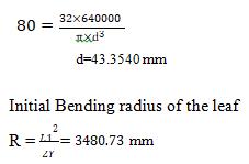
C. Design for the leaf spring (Analytical method)
D. Analytical Method
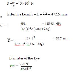
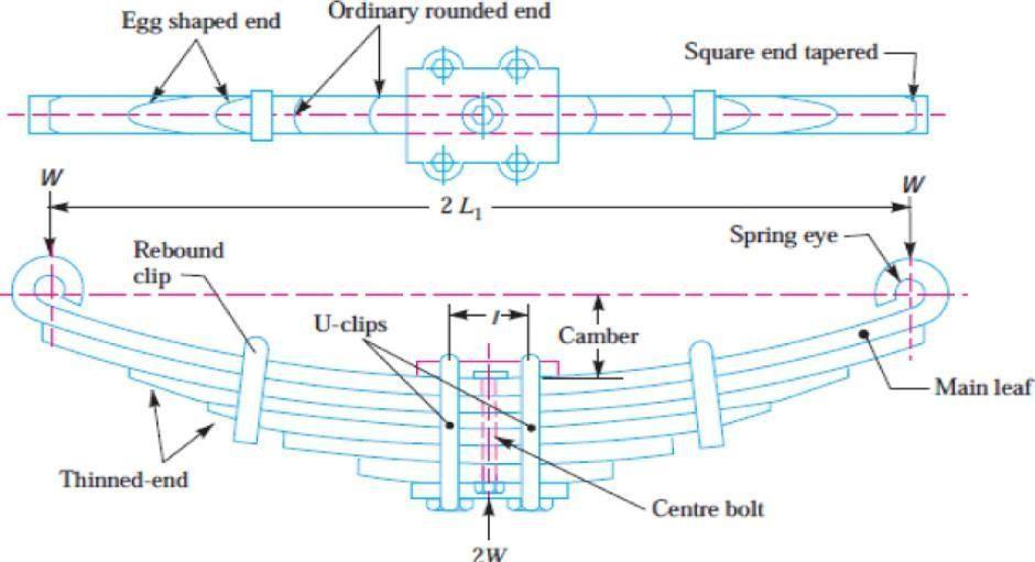
Design of a multilayer Leaf spring.Number of leaf's n=12
Span length 2L1=1025mmCentral Band l=80mm Load applied=80KN Thickness =16mm
Width =60mmSolution:
n=ne+ng
12=2+10 (where ne=full length leaf & ng= graduated leaf)
ISSN: 2321-9653; IC Value: 45.98; SJ Impact Factor: 7.538
Volume 11 Issue III Mar 2023- Available at www.ijraset.com
Clearance value and σb are referred from DDHB & DME-IITextbook.(c=2mm; σb =80N/mm2)
1) After creating the Catia model using the dimensions from the analytical method using Catiav5. Save the model in “IGS” format.
2) Import the Catia model to the Ansys workbench to perform a static structural modulefor static analysis.
3) Create a structural steel material or else it will be automatically saved in the engineeringdata.
4) Provide the required material properties in the engineering data.
5) Create the meshing for the leaf spring.
6) Applying the constraints to the model.
7) Run the analysis.
8) We get the Von mises stress and total Deformation for the finite element analysis.

2)


ISSN: 2321-9653; IC Value: 45.98; SJ Impact Factor: 7.538
Volume 11 Issue III Mar 2023- Available at www.ijraset.com
3)
ISSN: 2321-9653; IC Value: 45.98; SJ Impact Factor: 7.538
Volume 11 Issue III Mar 2023- Available at www.ijraset.com
B. Case-II: Composite leaf spring (Carbon fibre reinforced polymer- CFRP)
As it was already mentioned, a suspension system operates comfortably when it has the capacity to absorb and store more energy. However, the issue with the spring's hefty weight continues to exist. This can be fixed by usingcomposite material in the traditional leaf spring instead of steel. So, using Catia, a virtual model of a leaf spring was produced. The material isassigned to the model after it has been imported into ANSYS. These outcomes can be comparedto those of the Structural steel leaf spring. below table 3 refers to composite material composition
• After creating Catia model using the dimensions from the analytical method using Catia v5. Save themodel in “IGS” format.
• Import the Catia model to theAnsys workbench to perform a Statical structural module for staticanalysis.
• Creating structural steel materials or else it will be automatically saved in the engineering data.
• Provide therequired material properties in the engineering data.
• Create the meshing for theleaf spring.
• Applying the constraints to the model.
• Run the analysis.
• We get the Von mises stress and total Deformation for the finite element analysis.
3)
ISSN: 2321-9653; IC Value: 45.98; SJ Impact Factor: 7.538
Volume 11 Issue III Mar 2023- Available at www.ijraset.com
Table.4: Comparison of analysis results for steel and composite leaf spring. Material
Steelleafspringsandcompositeleafspringshaveundergonedesign and staticstructuralstudy. Comparing compositeleaf springs with steel leaf springs of the same design and load-carrying capacity has been done. For both steel and composite leaf springs, the stress and displacements have been computed analytically and with ANSYS. According to the findings of the static analysis, the steel leaf spring has a maximum displacement of 37.35 mm, and the corresponding displacement for CFRP is 31.426 mm. The findings of the static analysis also reveal that the steel leaf spring's von-Mess stress is 422.83 MPa and the CFRP's is 379.79 MPa. Lower displacements and stresses are seen in the composite leaf springs than the steel leaf springs.


[1] Erol Sancaktar , Mathieu Gratton “Design analysis & and optimization of composite leaf springs for light vehicleapplications." issued on February–March 1999.

[2] Nishant Varma, Ravi Ahuja, T Vijaykumar, C Kannan “Design & Analysis of composite mono leaf spring forpassenger cars”. Issued on October 2020.
[3] Guang Cheng,Kaiyauan Chen, Ynanchang Chen “Fracture on the two layer leaf spring”. issued on 10 December2021.
[4] Chen Qian, Wenknshi, Zhiyong Chen Shixiang, Yang Qianqian Song “Fatigue reliability design of composite leafsprings based on ply scheme optimization”. Issued on February 2017.
[5] Keerthi vasan S.M shibi C. K Tamilselvan “Testing of composite leaf spring using carbon, glass & aramid fiber".Issued on 30 May 2019.
[6] Pulkit Solanki, Ajay Kumar Kaviti “Design and computational analysis of semi-elliptical& parabolic leaf spring".Issued on 2018.
ISSN: 2321-9653; IC Value: 45.98; SJ Impact Factor: 7.538
Volume 11 Issue III Mar 2023- Available at www.ijraset.com
[7] T.G. Loganathan, K. Vinoth Kumar’s. Madhu “Flexural and fatigue life of a composite leaf spring using finiteelement analysis”. Issued on 20 November 2019.
[8] K. Ashwini C.V. MohanRao“Design and Analysis ofLeafSpringusing VariousComposites”. Issued on24 March2018.
[9] J.J. Fuentes H.J. Aguilar, J.A.Rodriguez b E.J. Herrera “Premature fracture in automobile leaf springs”. Issued on
[10] K.S. Ashraff Ali D. Joseph Manuel M. Balamurugan M. Sangili Murugan“Analysis of composite leaf spring using ANSYS software”. Issued on 5 August 2020.
[11] Stephan Krall, Richard Zemann “Investigation of the Dynamic Behavior of CFRP Leaf Springs”. Issued on 24February 2015.
[12] Birham Alemu Tadesse,O. Fatoba “Design optimizationand numerical analysis of composite leaf spring in a heavy-duty truck vehicle”. Issued on January 2022
[13] Donghui LI, Zhenwei FAN, Yewei ZHANG; Jian ZANG, Eengtian YANG “Optimum Design and Experiment ofcomposite leaf spring landing gear for electric aircraft”. Issued on 10 June2020.
[14] K Mahadevan, K balaveera Reddy “Design Data Handbook for Mechanical Engineers”. 978-81-239-2315-4.
[15] A S Ravindra, “Design of Machine Elements II” ISBN-13:978-81-239-2633-9.