10 XII December 2022 https://doi.org/10.22214/ijraset.2022.47815
& Engineering Technology (IJRASET)

ISSN: 2321-9653; IC Value: 45.98; SJ Impact Factor: 7.538 Volume 10 Issue XII Dec 2022- Available at www.ijraset.com

& Engineering Technology (IJRASET)
ISSN: 2321-9653; IC Value: 45.98; SJ Impact Factor: 7.538 Volume 10 Issue XII Dec 2022- Available at www.ijraset.com
Nilesh Chavan1, Sourabh Solanke2 , Prajwal Sute3 , Tanya Samanta4 , Prof. P. A. Wankhade5 1, 2, 3, 4Student, 5
Abstract: Planetary Gear Trains are extensively used for power transmission and are the most critical component. This report focuses on the designing and analysis of a planetary gearbox for an SAE BAJA All-Terrain Vehicle (ATV). The conventional two-stage speed reduction gearbox is bulkier and has a high volume to power ratio. A planetary gearbox gives the best balance between weight and power to be transmitted. For the design procedure standard method is utilized. Based on conventional equations gear calculations are performed and subsequently, CAD modeling for various parts is done. The analysis for each component is performed and checked for its stresses. The transmission shafts and bearings are designed using the standard force equations. In addition, the design and analysis of gearbox casing is performed and the complete assembly is checked for interferences. This report also presents the advantages and limitations of planetary gear train over other transmission systems. The comparison of planetary gear system with compound spur gear system is done on the basis of volume and weight, ease in manufacturing, assembly and disassembly and aesthetical viewpoint.
Keywords: Planetary Gearbox, All-Terrain Vehicle (ATV), Volume to power ratio, Designing, CAD modeling, Analysis, Gearbox casing, Ease in manufacturing, Aesthetic
Planetary gear Train also referred to as epicyclic gear Train consists of three elements sun gear, planet gear, and ring gear. Sun gear is located at the centre that transmits torque to planet gears orbiting around the sun gear. Both systems are located inside the ring gear. In the toothed formation, sun and planet gears are in external meshing while planet gears and ring gear are internally meshed. The planetary gear train is found in many variations and arrangements to meet a broad range of speed-ratio in the design requirements. Now, industrial applications demand high torque in a compact (a high torque/volume) and light (a high torque/weight ratio) package. In a planetary gear train, torque density can be increased by adding more planets through multiple gear mesh points. This means a planetary gear with say three planets can transfer three times the torque of a similar-sized fixed axis standard spur gear system. The applied load to planetary gears is distributed onto multiple gear mesh points means the load is supported by N contacts (where N = the number of planet gears) increasing the torsional stiffness of the gear train by factor N. Hence it lowers the lost motion compared to similar size standard gear trains. Planetary gears with deep groove ball bearings are frequently used in applications in which high radial loads occur. Hence, they are used to develop a hub drive system for an automobile. Automated Guided Vehicles and Mobile Satellite Receivers are other applications of a planetary gearbox.
For proposed application, a four-stroke cycle, air-cooled engine would serve the purpose. This segment has considered Briggs & Stratton (B&S) 10 HP overhead valve engine (OHV) intake Engine as a prime mover/Powertrain. This engine develops a maximum torque of 18.98 N-m at 2800rpm and a peak power of 10 HP at 3800 rpm.
The main objective of the transmission is to provide to the drive more than enough torque to the wheels from the engine. Enough torque means torque required to pull the driving wheels against the road loads. To choose the transmission capable of producing enough torque to propel the All-Terrain Vehicle (ATV), it is necessary to determine the total tractive effort (TTE) requirement of the vehicle.
Following are the design parameters selected for the vehicle
Gross vehicle weight (car + driver) 170+70 = 240 kg
Weight distribution ratio =0.6
Maximum engine torque 18.98 N-m
ISSN: 2321-9653; IC Value: 45.98; SJ Impact Factor: 7.538 Volume 10 Issue XII Dec 2022- Available at www.ijraset.com
Engine power 10 Hp = 7.5 kW
Wheel diameter 0.534 m = 21 inches
CVT low reduction ratio =3.7
Power transmission efficiency =90%
Co-efficient of static friction 0.8 (sand) 0.9 (concrete)
Co-efficient of rolling resistance (Fr) =0.05 (sand)and 0.014 (concrete)
Air density =1.122 kg/m3
Frontal area of ATV =1.055 m2
Drag co-efficient= 0.44
Vehicle velocity (initially assumed)= 20 kmph
Total Tractive Effort (TTE) = RR+AR+GR
Where,
RR=Rolling Resistance= Gross Vehicle Weight x coefficient of rolling resistance
AR=Aerodynamic Resistance= Where = air density
A = frontal area of car v = vehicle velocity Cd = air drag coefficient
GR=Grade Resistance= Vehicle weight x sin ( ) Where = inclination angle of plane Now, TEMax = x 0.6 x x cos Where, μ = Static Friction Coefficient 0.6 = Rear Weight Distribution Torque required at wheels is, = TE x x r
To calculate speed reduction ratio. Net reduction ratio = output torque input torque x η Where, η = power transmission efficiency Our power transmission layout includes the use of a continuous variable transmission or CVT to further provide speed reduction and torque multiplication.
This CVT has fixed specifications as per given by the manufacturer and we use a Just In Time CVT that has a speed reduction ratio of 3.7
Therefore,
Speed reduction ratio, i = net reduction ratio/3.7
By performing above calculations, we get, Rolling Resistance=117.72 N (for sand)
Aerodynamic Resistance =8.038 N Grade Resistance=995.012 N
Total Tractive Effort =1120.77 N
Maximum Tractive Effort =1194.934 N Torque at the wheels =320 N-m Net reduction ratio =18.7
Final Speed reduction ratio= 5
ISSN: 2321-9653; IC Value: 45.98; SJ Impact Factor: 7.538 Volume 10 Issue XII Dec 2022- Available at www.ijraset.com
20MnCr5 is Chrome-Manganese Carburizing Steel generally supplied annealed to HB 229(max). Carburized and heat-treated, it develops a hard wear resistant case of HRC 60-63 and a tough strong core with a typical tensile strength range of 900-1300 MPa. This material can be easily acquired by vendors and can undergo the required heat treatment for our application. It is low alloy steel capable of being hardened which provides a tough core and can be case hardened by carburizing or carbonitriding to achieve a hard case
We choose the following parameters for sun gear: Pressure angle, ∅ = 20° Module, m= 2 mm
Number of teeth, Zs =20 (as per AGMA standards)
For epicyclic gear train following criteria should be satisfied: m (Zp +2) < m(Zp + Zs) ( /n) Where, n is Number of planet gear
Number of teeth on sun gear = Zs Number of teeth on planet gear = Zp Number of teeth on ring gear = Zr
Therefore, L.H.S: 2(30+2) = 64 R.H.S: 2(20+30) sin ( /2) = 100 L.H.S < R.H.S
Hence, above criteria is satisfied. Since i=5 and Zs=20 According to i = + /Z Zr = 80 = ( ∗ – ∗ ) = m = /
By using above equation,
Pitch Circle Diameter of sun gear: 40 mm
Pitch Circle Diameter of planet gear: 60 mm
Pitch Circle Diameter of ring gear: 160 mm
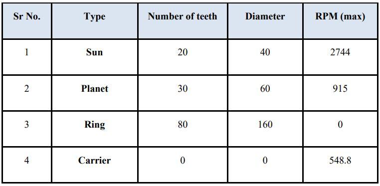
For Calculation of Speeds, α = Rotation of sun gear β = Rotation of carrier (+ and – signs are used in below table to distinguish between the direction of rotation) In our case Ring gear is stationary hence, Its RPM is 0. …(1) –( / ) ∗ α + =0
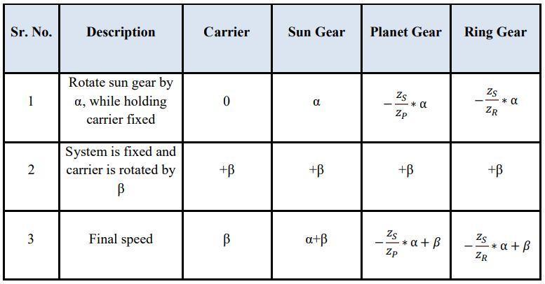
We know the maximum engine speed hence, Speed at the sun gear, Engine Speed∗ηCVT / CVT reduction = 3800∗0.65/0.9 = 2744 rpm Hence, α + β = 2744 rpm …(2)
Solving above two equation, we get Taking equations from above table and finding rpm for each component we get Planet Speed = 915 rpm Carrier speed = 548.8 rpm Sun Speed = 2744 rpm
ISSN: 2321-9653; IC Value: 45.98; SJ Impact Factor: 7.538 Volume 10 Issue XII Dec 2022- Available at www.ijraset.com
Tangential Load (Ft) is important because it determines the magnitude of torque and consequently the power, which is transmitted. ( ) = ( )x ℎ ( ) ℎ ( ) = x x /60 = x 40 x 2800 3.7/60 x 1000 = 1.58 / Where,
D = pitch circle diameter of sun gear N = RPM of sun gear at maximum torque condition
We know that, P = 7.5 kW Therefore, we calculate, = / = 7.5 x 1000/1.58 Ft = 4734.42 N
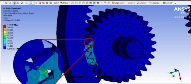
Allowable Stresses
Step 1: Lewis Equation = x x Where, = Allowable Stress on Gear Pc = Circular pitch = = 6.28 mm y = Form Factor based on Tooth Profile and number of Teeth = 0.154 0.912 = 0.1084
b = Face Width of Gear First, we need to find the Allowable Stress by following the further mentioned steps: = Ultimate strength of material = 1200 MPa FOS = factor of safety = 2 = safe ultimate stress = / = 1200/2 = 600 MPa Cv = velocity factor = 6/(6 + ) = 0.8 = x C = 480 MPa
We use the Lewis Equation to find the face width of the gear. b = 20 mm
Step 2: Beam Strength (Fs)
It is the maximum value of tangential force that the tooth can transmit without bending failure. It is determined by using the Lewis Equation which assumes the tooth as a cantilever beam. After finding face width (b), we can calculate the beam strength of the gear by considering the gear tooth as a cantilever beam under tangential load.
= x x x = 600 x 6.283 x 0.1084 x 20 = 8169 N
Step 3: Dynamic Load (Fd) The gears rotate at an appreciable speed and it becomes necessary to consider the dynamic force resulting from the impact between mating teeth. It is induced due to the following factors:- •
ISSN: 2321-9653; IC Value: 45.98; SJ Impact Factor: 7.538 Volume 10 Issue XII Dec 2022- Available at www.ijraset.com
Errors in tooth spacing
Misalignment between bearings
It is the sum of tangential load (Ft) and dynamic induced load (Fi).
To calculate Fi;
Fi = [21 x ( + )] / [21 + √( + )]
Where, C = deformation factor = 0.111 / ( (1/ ) + (1/ ) )
E = young’s modulus of sun and planet gear
Es = Ep = 2 x 10⁵ N/mm2
Therefore, C = 11100 MPa
e = error occurred during gear manufacturing = 10.205 mm (from PSG data book) Hence, we can calculate, Fi = 1991.462 N
To find dynamic load Fd = Ft + Fi = 4734.418 + 1991.462 N Fd = 6725.879 N
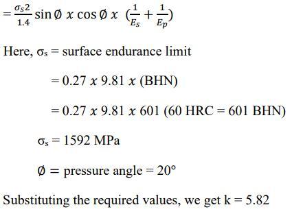
STEP 4: Wear Strength (Fw)
It is the maximum value of tangential force that the tooth can transmit without pitting failure. Pitting occurs when the contact stress reaches the magnitude of the surface endurance strength. = x x x
Where, D = pitch circle diameter of sun gear = 40mm b = face width = 20mm Q = ratio factor = 2 / ( +1)
Where, i = Speed reduction ratio Hence, Q = 1.667
k = Load stress factor = Therefore, Fw = 40 x 20 x 1.667 x 5.82
Fw = 7756.444 N
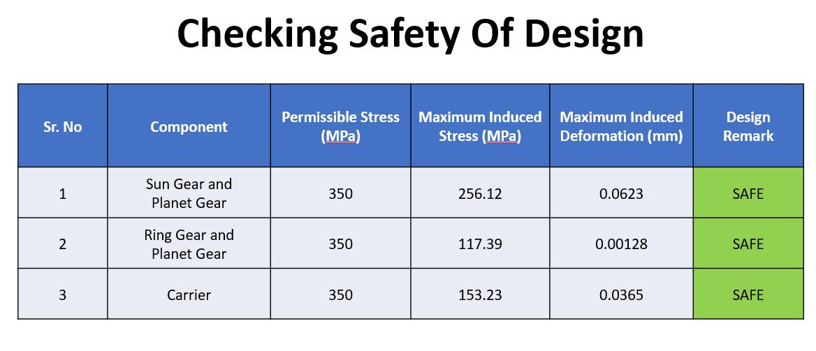
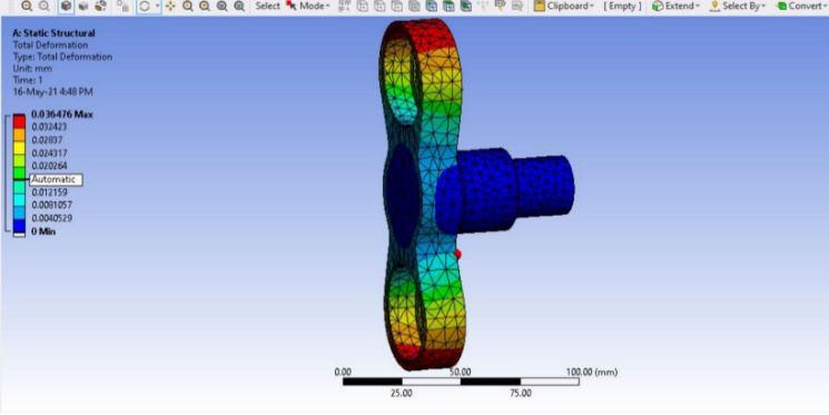
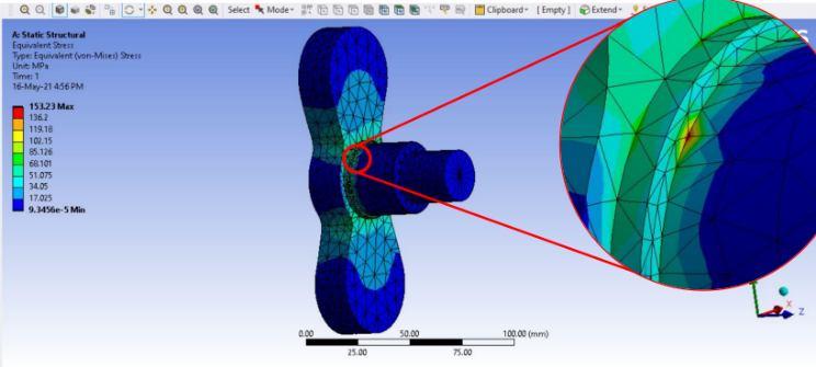
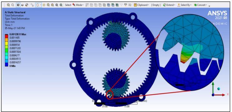
STEP 5: Criteria of safety
After all the necessaryloads are found, we have to determine if the gear can sustain these loads without bending and wear failure. For this purpose, we use the following criteria to ensure a safe design:
Static load (or beam strength) should be greater than dynamic load- Fs > 1.2 Fd
Wear load should be greater than dynamic load- Fw > Fd For shaft and bearing design standard procedures have been followed along with design data book.
ISSN: 2321-9653; IC Value: 45.98; SJ Impact Factor: 7.538 Volume 10 Issue XII Dec 2022- Available at www.ijraset.com

ISSN: 2321-9653; IC Value: 45.98; SJ Impact Factor: 7.538 Volume 10 Issue XII Dec 2022- Available at www.ijraset.com
ISSN: 2321-9653; IC Value: 45.98; SJ Impact Factor: 7.538 Volume 10 Issue XII Dec 2022- Available at www.ijraset.com
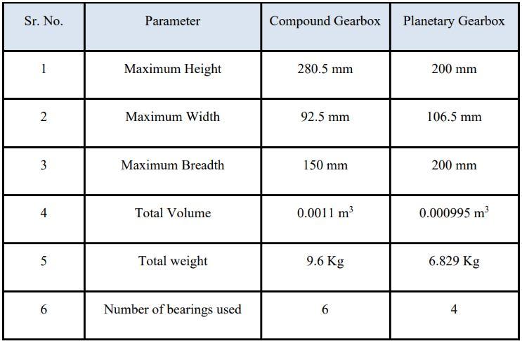
2) Above table explicitly shows that our designed planetary gearbox is much better than the existing compound gearbox.
3) The designed planetary gear train is 10% smaller in size and 2.8 kg lighter than the compound spur gear train. At the same time number of bearings used is reduced significantly.
1) The purpose of this project was to design a planetary gear train suitable for All-Terrain Vehicle (ATV) where space and weight constraints were the prime objectives.
2) In the designed planetary gearbox reduction ratio of 5:1 is achieved in a single stage rather than two stage in the compound spur gearbox for the same reduction ratio.
3) The weight of the planetary gear train is 2.8 kg less than the compound spur gearbox while the size reduction attained is 10%.
4) The proposed planetary gear train successfully meets the intended objectives.
[1] University of Manitoba SAE (UMSAE) Baja Transmission Design, Final design report, 12-05-2011, Project Advisors: Malcolm Symonds & Paul Labossiere. Names of Team Members: Brian J. Nuessle, John M. Bais, Steven N. Young, Qiankun Zhao
[2] Bernd-Robert Höhn, Karsten Stahl and Philipp Gwinner Light-Weight Design for Planetary Gear Transmissions‖ GEAR TECHNOLOGY, Sept. 2013, PP: 96103
[3] Design and Analysis of Gearbox for SAE BAJA Competition Anjali Mukeshkumar Sah, Naved Anwar Husain Farooqui. International Journal of Engineering Research & Technology (IJERT) ISSN: 2278-0181 Vol. 9 Issue 05, May-2020
[4] DESIGN OF TWO-STAGE PLANETARY GEAR TRAIN FOR HIGH REDUCTION RATIO Prabhakar Vitthal Pawar1, P.R. Kulkarni2. 1) M.E. (Design ), Mechanical Engineering, Walchand Institute of Technology, Solapur-413003, Maharashtra, India. 2) Professor, Mechanical Engineering, Walchand Institute of Technology, Solapur-413003, Maharashtra, India. IJRET: International Journal of Research in Engineering and Technology eISSN: 2319-1163 | pISSN: 23217308
[5] Design Analysis of Industrial Gear Box Casing- Balasaheb Sahebrao Vikhe
[6] Design and Analysis of an Epicyclic Gearbox for an Electric Drivetrain Timir Patel, Ashutosh Dubey, Lokavarapu Bhaskara Rao International Journal of Recent Technology and Engineering (IJRTE) ISSN: 2277-3878, Volume-8 Issue-3, September 2019 [7] S. B. Nandeppagoudar, S.N.Shaikh, S. R. Gote, S. P. More, A. S. Chaudhari, N. R. Borse, S.H.Gawande, “Design and Numerical Analysis of Optimized Planetary Gear Box,” IOSR (Journal of Mechanical and Civil Engineering), March 2017